← All firearms · Printable work order
AR-15 (M16/M4 Pattern)
- easy
- Shop tier 2
- high confidence
- Rifle
- modular
- direct impingement
- service rifle
- toolless field strip
- beginner friendly
field strip ~2 min · reassembly ~3 min · detail strip ~25 min
Specifications
- Manufacturer
- AR-15 Pattern (multiple manufacturers)
- Origin
- United States
- Category
- Rifle
- Action
- Gas, direct impingement
- Calibers
- 5.56x45mm NATO, .223 Remington, 300 AAC Blackout, 6.5 Grendel, .224 Valkyrie
- Capacity
- 30+1 with a standard STANAG magazine
- Production
- 1959–present (in-production)
- Also known as
- M16, M4 Carbine, AR-15A2, MSR
Model-specific safety
- The safety selector can only be engaged when the hammer is cocked. If the selector will not rotate to SAFE, the hammer is down — that is a condition to resolve, not to force.
- The bolt cam pin MUST be installed. Without it the bolt cannot lock into the barrel extension, and firing the rifle in that condition can destroy it and seriously injure the shooter. The firing pin retaining pin will not install without the cam pin in place — that is a designed safeguard, and if the retaining pin will not go in, stop and find out why.
- The buffer and buffer spring in the receiver extension are under compression. When you depress the buffer retainer, control the buffer — it will launch out of the tube.
- Gas system components are extremely hot immediately after firing. Let the rifle cool before disassembly.
- Removing the magazine does not clear the chamber. Lock the bolt back and inspect.
If it will not go back together
Common ways this firearm resists reassembly, and what is actually wrong. Forcing a part that will not seat is how firearms get damaged.
-
The firing pin retaining pin will not go in.
Why The cam pin is missing, or is in but not rotated 90 degrees.
Fix Drop the cam pin into its hole and rotate it a quarter turn, then seat the firing pin and fit the retaining pin.
Forcing it Never force the firing pin. If the cam pin is unrotated the bolt cannot lock and the rifle is unsafe to fire.
Under spring tension
- Buffer and buffer spring in the receiver extension
- Extractor spring and insert
- Magazine springs
Easily lost parts
Bolt cam pin · Firing pin retaining pin (cotter pin) · Extractor pin · Buffer retainer and its spring
Tools
| Tool | Required | Used for | Substitute |
|---|---|---|---|
| Punch or a cartridge rim | Optional | Pushing out stubborn takedown pins on a tight rifle. | The rim of a fired case, or the tip of a bullet on a loaded round — though using ammunition as a tool is a habit worth avoiding. |
| Small punch or paperclip | Optional | Removing the firing pin retaining pin from the bolt carrier group. |
Shop difficulty
Shop tier 2 Tier 2 — moderate among rifles and carbines, for the full job: strip to the parts that get coated and put it back together working. About 72 key numbers, and the bolt is broken out. It all comes apart with punches and a couple of AR wrenches. The known traps are the spring-loaded pivot and takedown detents, the roll pins that mar the receiver, the ejection port cover spring that has to be pre-wound, and the hammer spring orientation. Barrel removal needs vise blocks and a torque wrench.
Parts: 92 numbered parts (complete rifle, M16A1 configuration (with forward assist), magazine included, per the TM 9-1005-249-23&P Repair Parts List figs. C-1 to C-14; semi-auto parts only: the automatic sear assembly (fig. C-), from TM 9-1005-249-23&P Unit and Direct Support Maintenance Manual (Including Repair Parts and Special Tools List): Rifle, 5.56mm, M16 and M16A1 — Departments of the Army and Air Force; Commandant, Coast Guard, p. Appendix C Section II, pp. C-1-1 to C-14 archive.org [11].
Bench time: about 40 min to strip, 60 min to rebuild (estimate). Estimate: full lower strip (fire control, bolt catch, mag catch, selector, detents, buffer/stock, trigger guard), BCG strip, upper strip (EPC, forward assist, charging handle, handguard, gas block, barrel off with wrench and vise block, muzzle device). Rebuild longer: detents, roll pins, port cover spring, barrel nut torque and gas tube indexing, function check.
Small parts: 18 pins, 19 springs, 6 detents or plungers (counted by name in the same list, as line items (M16A1, auto parts excluded). Pins = every 'PIN,...' entry except the firing pin (cam pin, firing pin retaining pin, extractor pin, spring pins, grooved)
What comes off for coating
- Lower receiver: pistol grip and screw (selector detent and spring), safety selector, takedown pin, detent and spring, pivot pin, detent and spring, hammer, hammer spring and pin, trigger, trigger spring, disconnector and spring, pin, bolt catch, plunger, spring and roll pin, magazine catch, spring and button, trigger guard and roll pin, buffer, buffer spring, buffer retainer and spring, stock, castle nut, end plate, receiver extension — roll-pin punches/starters, pivot pin detent tool, castle nut wrench
- Upper receiver: charging handle, bolt carrier group (firing pin, retaining pin, cam pin, bolt, extractor, spring, insert, ejector, ejector spring and pin, ejection port cover, pin, spring and clip, forward assist, spring and pin, rear sight, handguard/rail, gas block or front sight base and pins, gas tube and pin, barrel nut and barrel, muzzle device and crush washer — upper receiver vise block, armorer's/barrel nut wrench, torque wrench, bench block, taper-pin punch
Special tools
- Upper receiver vise block / reaction rod — Holding the upper for barrel nut and muzzle device work
- AR armorer's wrench (barrel nut/castle nut) — Barrel nut and receiver extension castle nut
- Torque wrench (ft-lb and in-lb) — Barrel nut, castle nut, muzzle device
- Pivot pin detent installation tool (or 3/32" punch) — Holding the pivot pin detent while the pin goes in
- Roll-pin starter punches (1/16", 3/32", 1/8") and a bench block — Bolt catch, trigger guard, forward assist and ejection port cover pins
- Lower receiver vise block — Supporting the trigger guard ears and bolt catch boss
Known pain points
- The front pivot pin and rear takedown pin each sit on a spring-loaded detent that launches when the pin comes out; reinstalling the pivot pin means holding the detent down while the pin goes in, which is the classic AR lower trap. (both)
Source: AR Lower Receiver Build: Pivot Pin Installation — Shooting Illustrated (NRA) shootingillustrated.com [35] — “The detent and spring will fly out and you will be spending a lot of time on your knees looking for them.” - The TM has the armorer use a pivot pin tool to compress the detent, and warns to catch the detent and spring as the pin comes out. (both)
Source: TM 9-1005-249-23&P, Rifle, 5.56mm, M16 and M16A1 (unit and direct support, incl. RPSTL) — Department of the Army archive.org [36] — “Catch detent and spring as pivot pin is” - The bolt catch and trigger guard roll pins mar the receiver unless the receiver is taped and supported and a roll-pin starter punch is used. (both)
Source: TFB Armorer's Bench: Complete AR15 Assembly - Lower Receiver — The Firearm Blog thefirearmblog.com [37] — “Installing the bolt catch roll pin can be cumbersome and in the wrong hands, aesthetically destructive.” - The ejection port cover spring has to be pre-wound half a turn and held while its pin goes in. (reassembly)
Source: TM 9-1005-249-23&P, Rifle, 5.56mm, M16 and M16A1 (unit and direct support, incl. RPSTL) — Department of the Army archive.org [36] — “Legs of spring must be positioned and pretensioned before the pin is installed.” - The hammer spring legs must ride on the trigger pin and the hammer has to be held down to line up the hammer pin; reversed, the hammer is weak. (reassembly)
Source: TFB Armorer's Bench: Complete AR15 Assembly - Lower Receiver — The Firearm Blog thefirearmblog.com [37] — “Make sure the wings of the hammer spring rest on the flats of the hammer assembly and apply pressure downward onto the hammer in order to line up the holes for the hammer pin.”
See also 1 documented reassembly problem and their fixes.
Fit or check on rebuild
- Barrel nut torque and gas tube alignment — The barrel nut is torqued within a range and indexed for the gas tube
Source: TM 9-1005-249-23&P, Rifle, 5.56mm, M16 and M16A1 (unit and direct support, incl. RPSTL) — Department of the Army archive.org [36] — “torque barrel nut assembly (8) to 30 ft-lb.” - Headspace if the barrel or bolt is changed — Bolt-to-barrel headspace is set by the factory; mixing bolts and barrels needs a gauge check
- Gas key staking and screw torque — If the carrier key is disturbed the screws are torqued and staked
Source: TM 9-1005-249-23&P, Rifle, 5.56mm, M16 and M16A1 (unit and direct support, incl. RPSTL) — Department of the Army archive.org [36] — “torque the carrier and key screws (3) to 35 to” - Function check (safety, hammer reset, disconnector) — The hammer spring orientation and disconnector seating are checked with a function check
- Sight/optic re-zero — The front sight base, rail or optic moves when the barrel/handguard comes off
This is Pew-Takedown's rating, not the manufacturer's. How tiers are rated. Forum reports are owners' experience, not specifications.
Procedures
Clear and Make Safe
Clear & Make Safe- Point the muzzle in a safe direction and keep your finger off the trigger.
- Press the magazine release and remove the magazine.Removed at this step:
Magazine - Pull the charging handle fully to the rear and lock the bolt back using the bolt catch.
- Visually inspect the chamber and the magazine well, then physically feel the chamber to confirm it is empty.WarningCheck both the chamber and the magazine well. A round can be hung up in the well.
- If the hammer is cocked, place the selector on SAFE. If the selector will not move to SAFE, the hammer is down — leave the selector alone and continue with the muzzle in a safe direction.TipOnce the upper and lower are separated, selector position no longer matters for disassembly.
- Remove all live ammunition from the work area.
Field Strip
Field StripSeparate the upper and lower, then remove the bolt carrier group and charging handle. No tools on most rifles.
- Complete the Clear and Make Safe procedure and release the bolt forward.
- Push the rear takedown pin from the left side of the lower receiver until it stops in its captured position.TipIf it is tight, tap it with a punch or the rim of an empty case rather than levering it.
- Pivot the upper receiver forward and away from the lower on the front pivot pin.
- Push the front pivot pin out from the left side to its captured position, then separate the upper receiver from the lower receiver.TipYou can stop here for most cleaning. Separating the receivers is optional if you only want to reach the bolt.Removed at this step:
Upper receiver assembly - Pull the charging handle partway to the rear. The bolt carrier group will follow it out of the upper receiver — grasp the carrier and withdraw it.Removed at this step:
Bolt carrier group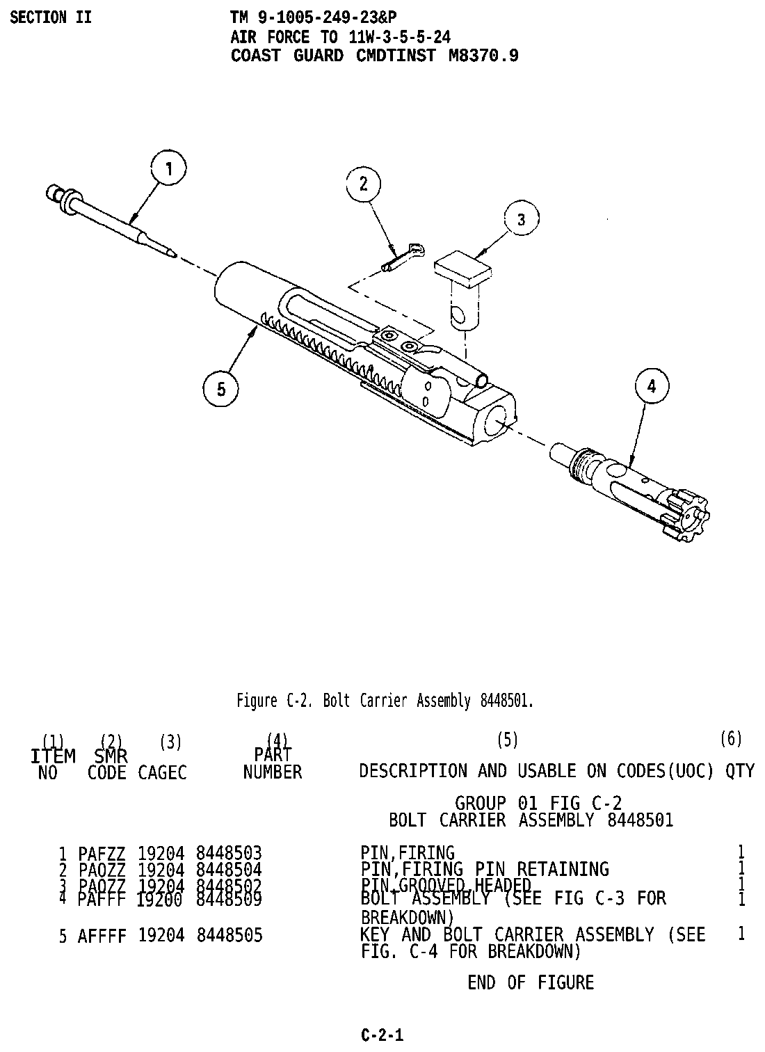
Bolt carrier assembly Carrier, key, bolt, cam pin and firing pin retaining pin — the parts that come apart during a field strip. TM 9-1005-249-23&P — Unit and Direct Support Maintenance Manual, Rifle, 5.56mm, M16 and M16A1, p.176 — Headquarters, Department of the Army. Source. Public domain (US Government work). - With the carrier out, pull the charging handle down and out of its channel in the upper receiver.WarningThe charging handle must come out after the carrier, not before. It will not clear its channel otherwise.Removed at this step:
Charging handle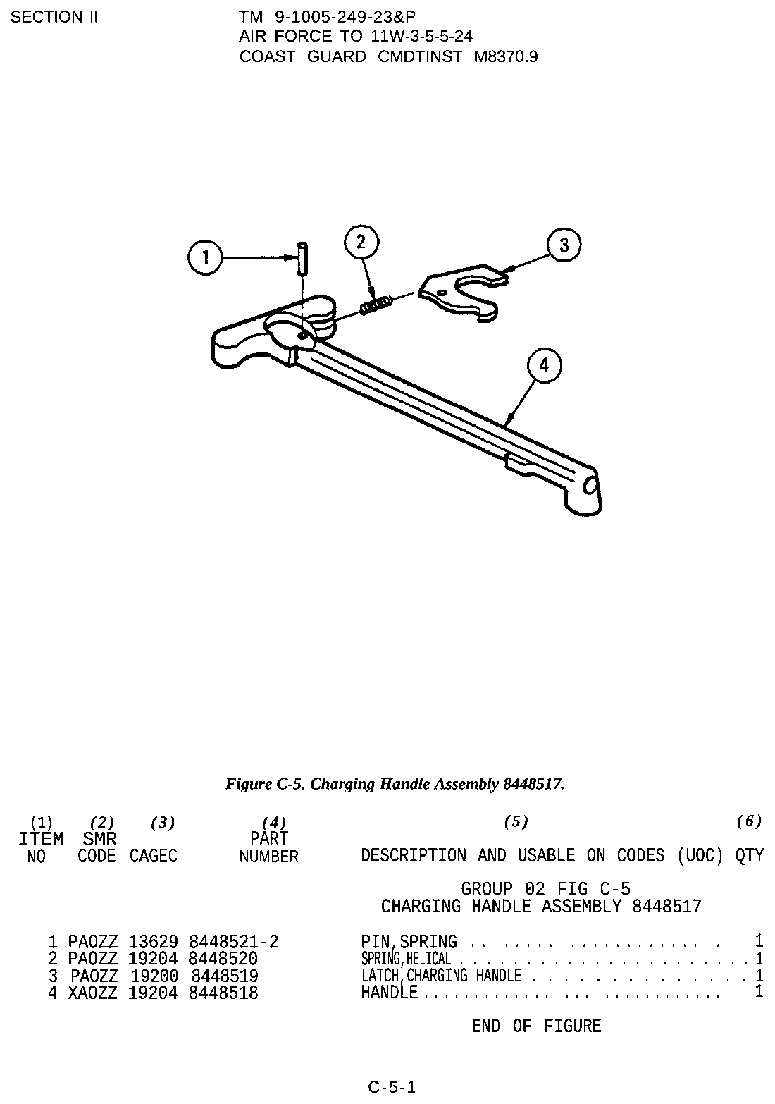
Charging handle assembly The latch, its spring and roll pin. Relevant if the latch has stopped holding. TM 9-1005-249-23&P — Unit and Direct Support Maintenance Manual, Rifle, 5.56mm, M16 and M16A1, p.179 — Headquarters, Department of the Army. Source. Public domain (US Government work).
Disassemble the Bolt Carrier Group
Detail Strip tools requiredRoutine — this is part of normal cleaning on a direct-impingement rifle.
- Remove the firing pin retaining pin (a small cotter pin) from the side of the carrier using a punch or your fingers.TipIt only needs to come out far enough to clear the firing pin — do not fully remove and lose it.Removed at this step:
Firing pin retaining pin - Tip the carrier back and let the firing pin drop out of the rear.WarningDo not pry the firing pin out. If it will not drop, the bolt is not pushed forward.Removed at this step:
Firing pin - Push the bolt forward into the carrier, rotate the cam pin 90 degrees, and lift it straight out.WarningThe cam pin is the single most important part not to lose. A rifle assembled without it is dangerous.Removed at this step:
Cam pin - Pull the bolt straight out of the front of the carrier.Removed at this step:
Bolt - To remove the extractor, push out the extractor pin with a small punch and lift the extractor and its spring assembly off the bolt.WarningThe extractor spring has a rubber or polymer insert that must not be removed or lost — it provides part of the extractor tension.Removed at this step:
ExtractorExtractor spring and insert - Clean the bolt tail, the carrier's interior, the gas rings, and the bolt lugs. Inspect the gas rings — their gaps should not all line up, and the bolt should hold its own weight when the carrier is stood on the bolt face.
Remove the Buffer and Buffer Spring
Detail Strip- Separate the upper from the lower receiver and verify the rifle is unloaded.
- Press the buffer retainer — the small pin at the front of the receiver extension — down with a fingertip while holding the buffer with your other hand.WarningThe buffer is under spring pressure and will launch forward. Keep a hand on it and wear eye protection.TipMake sure the hammer is cocked before you remove or install the buffer (TM 9-1005-319-23&P).
- Ease the buffer and buffer spring forward and out of the receiver extension.Removed at this step:
BufferBuffer spring - To reinstall, insert the spring and buffer, compress until the buffer nose clears the retainer, and let the retainer snap up in front of it.WarningConfirm the buffer retainer has popped back up and is holding the buffer. If it has not, the buffer will come out when the upper is removed and the spring can launch.
Remove the pistol grip, buttstock, takedown pin and pivot pin
Detail Strip tools required gunsmith recommendedTM 9-1005-319-23&P para 2-17a, steps 1–6. The TM's step 7 (buffer and action spring) is the entry's existing 'buffer-removal'. Unit maintenance (chapter 2) — above operator level.
Follows TM 9-1005-319-23&P (Air Force TO 11W3-5-5-42), Unit and Direct Support Maintenance Manual incl. RPSTL: Rifle, 5.56 mm, M16A2; Carbine, 5.56 mm, M4/M4A1 (with Changes 1-5) — Headquarters, Department of the Army / Department of the Air Force, para 2-17a (pp. 2-57 to 2-59) archive.org [5]
- Separate the upper receiver from the lower receiver (entry's field strip).
- Remove the pistol grip screw and lockwasher.Removed at this step:
ScrewLockwasher - Carefully remove the pistol grip and catch the helical spring and safety detent.WarningTo avoid injury to your eyes, use care when removing and installing spring-loaded parts.Removed at this step:
Pistol gripHelical springSafety detent - Fixed rifle stock: remove the self-locking buttstock screw.WarningIf the self-locking screw is removed, it must be discarded and replaced with a new one.Removed at this step:
Self-locking screw - Fixed rifle stock: remove the buttstock assembly carefully and catch the helical spring, takedown pin detent, takedown pin and stepped spacer.WarningTo avoid injury to your eyes, use care when removing and installing spring-loaded parts.TipIf the detent will not come out, use a wire to push it out.Removed at this step:
Buttstock assemblyHelical springTakedown pin detentTakedown pinStepped spacer - Collapsible carbine stock: extend the buttstock, grasp the lock release lever near its retaining nut, pull it downward and slide the buttstock to the rear off the lower receiver extension.Removed at this step:
Buttstock assembly - Depress the pivot pin detent and spring and remove the pivot pin, or insert the fabricated pivot pin removal tool to compress the detent, turn the pivot pin a quarter turn, then remove the tool and the pivot pin.WarningTo avoid injury to your eyes, use care when removing and installing spring-loaded parts.Removed at this step:
Pivot pin - Hold a cupped hand in front of the pivot pin detent and helical spring as the pin comes out, to catch them.TipIf the helical spring will not come out, use a wire to pull it out.Removed at this step:
Pivot pin detentHelical spring
Remove the bolt catch, magazine catch, selector, hammer and trigger
Detail Strip tools required gunsmith recommendedTM 9-1005-249-23&P para 3-16a (M16/M16A1), the semiautomatic parts only. Pistol grip and buttstock come off first (TM 9-1005-319-23&P para 3-13 lists them as removed). Direct support maintenance (chapter 3).
Follows TM 9-1005-249-23&P Unit and Direct Support Maintenance Manual (Including Repair Parts and Special Tools List): Rifle, 5.56mm, M16 and M16A1 — Departments of the Army and Air Force; Commandant, Coast Guard, para 3-16a (pp. 3-50 to 3-52) archive.org [11]
- Remove the pistol grip and buttstock (procedure 'lower-receiver-grip-stock-pins-removal').
- Remove the bolt catch spring pin with a 3/32-inch drive pin punch and hammer.Removed at this step:
Spring pin - Remove the bolt catch, bolt catch plunger and bolt catch spring.Removed at this step:
Bolt catchBolt catch plungerBolt catch spring - Press in on the magazine button with a drive pin punch and turn the magazine catch counterclockwise to unscrew and remove it.WarningTo avoid injury to your eyes, use care when removing and installing spring-loaded parts.Removed at this step:
Magazine catch - Remove the magazine button and magazine catch spring.Removed at this step:
Magazine buttonMagazine catch spring - Remove the safety selector lever.TipAt this point the military rifle has an additional part that the semiautomatic AR-15 does not have; it is not covered here.Removed at this step:
Safety selector lever - With the hammer forward, push the hammer pin out of the lower receiver with a drive pin punch.WarningTo avoid injury to your eyes, use care when removing and installing spring-loaded parts.TipIf the selector lever is still installed, the TM places it on SEMI for this step.Removed at this step:
Hammer pin - Remove the hammer assembly.Removed at this step:
Hammer assembly - Push the trigger pin out from the left side of the lower receiver with a drive pin punch.Removed at this step:
Trigger pin - Remove the disconnector and trigger assembly from the lower receiver.Removed at this step:
DisconnectorTrigger assembly
Remove the hammer and trigger springs
Detail Strip gunsmith recommendedTM 9-1005-249-23&P paras 3-17a and 3-18a, after the hammer and trigger are out of the receiver. Direct support maintenance (chapter 3).
Follows TM 9-1005-249-23&P Unit and Direct Support Maintenance Manual (Including Repair Parts and Special Tools List): Rifle, 5.56mm, M16 and M16A1 — Departments of the Army and Air Force; Commandant, Coast Guard, para 3-18a (p. 3-61) archive.org [11]
- Remove the hammer spring from the hammer.Removed at this step:
Hammer spring - Remove the disconnector spring and trigger spring from the trigger.WarningTo avoid injury to your eyes, use care when removing and installing spring-loaded parts.Removed at this step:
Disconnector springTrigger spring
Remove the trigger guard and lower receiver extension
Detail Strip tools required gunsmith recommendedTM 9-1005-319-23&P para 3-16a, rifle and carbine. Buffer, action spring and buttstock come out first. Direct support maintenance (chapter 3).
Follows TM 9-1005-319-23&P (Air Force TO 11W3-5-5-42), Unit and Direct Support Maintenance Manual incl. RPSTL: Rifle, 5.56 mm, M16A2; Carbine, 5.56 mm, M4/M4A1 (with Changes 1-5) — Headquarters, Department of the Army / Department of the Air Force, para 3-16a (pp. 3-77 to 3-78.1) archive.org [5]
- Remove the buffer and action spring (entry's 'buffer-removal') and the buttstock (procedure 'lower-receiver-grip-stock-pins-removal').
- Remove the trigger guard spring pin with a 1/8-inch drive pin punch and hand hammer.Removed at this step:
Spring pin - Remove the trigger guard.Removed at this step:
Trigger guard - Fixed rifle stock: put padding between the lower receiver and brass vise jaws that conform to it, and clamp the solid portion of the lower receiver just tight enough to hold.
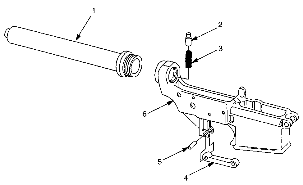
- Fixed rifle stock: unscrew the lower receiver extension with the combination wrench and socket wrench handle, catching the buffer retainer and helical spring.WarningTo avoid injury to your eyes, use care when removing and installing spring-loaded parts.Removed at this step:
Lower receiver extensionBuffer retainerHelical spring - Carbine: clamp the solid portion of the lower receiver in a vise with wooden jaws, just tight enough to hold.
- Carbine: loosen the extension locking nut with the special tool.Removed at this step:
Locking nut - Carbine: loosen the locking nut far enough for the receiver end plate to disengage from the lower receiver, hold the buffer retainer and spring in place with your index finger, and unscrew the lower receiver extension.WarningRestrain the pivot pin spring and detent while doing this (TM caution).Removed at this step:
Lower receiver extensionReceiver end plateBuffer retainerHelical spring
Remove the handguards, front sight post, sling swivel and ejection port cover
Detail Strip tools required gunsmith recommendedTM 9-1005-319-23&P para 2-16a. Each item comes off only when it needs repair or replacement, as the TM's notes say. Unit maintenance (chapter 2) — above operator level.
Follows TM 9-1005-319-23&P (Air Force TO 11W3-5-5-42), Unit and Direct Support Maintenance Manual incl. RPSTL: Rifle, 5.56 mm, M16A2; Carbine, 5.56 mm, M4/M4A1 (with Changes 1-5) — Headquarters, Department of the Army / Department of the Air Force, para 2-16a (pp. 2-45 to 2-48) archive.org [5]
- Separate the upper receiver and barrel assembly from the lower receiver.
- Push down on the handguard slip ring and lift the upper handguard assembly up and out.WarningDo not use a screwdriver or any other tool when removing the handguard assemblies — it may damage them or the slip ring. Do not remove the heat shield for any reason.TipThe operator's manual describes a 'buddy system' for this.Removed at this step:
Upper handguard assembly - Push down on the handguard slip ring and lift the lower handguard assembly up and out.Removed at this step:
Lower handguard assembly - Only if damaged: remove the front sight post by turning it counterclockwise with a dummy cartridge or the front sight post removal and installation tool.WarningTo avoid injury to your eyes, use care when removing and installing spring-loaded parts.Removed at this step:
Front sight post - Catch the front sight detent and helical spring.Removed at this step:
Front sight detentHelical spring - Rifle, only if repair is necessary: knock out the tubular rivet with a hammer and punch, remove the small sling swivel and discard the rivet.Removed at this step:
Small sling swivelTubular rivet - Carbine, only if repair is necessary: remove the two spring pins, lift the swivel locking bar up and out of the swivel mount, remove the swivel mount, then remove the rivet and separate the front swivel from the mount.Removed at this step:
Spring pinsSwivel locking barSwivel mountFront swivel - Only if repair is necessary: remove the retaining ring and slide the headless grooved pin out to the rear.TipThe pin may bind against the forward assist housing and need some extra force.Removed at this step:
Retaining ringHeadless grooved pin - Catch the cover spring and ejection port cover as the pin comes out.Removed at this step:
Cover springEjection port cover
Remove the gas tube, compensator and barrel
Detail Strip tools required gunsmith recommendedTM 9-1005-319-23&P para 3-10a (M16A2 / M4): gas tube, compensator and peel washer, then the barrel nut is loosened and the barrel separated from the upper receiver. Barrel work affects headspace. Direct support maintenance (chapter 3).
Follows TM 9-1005-319-23&P (Air Force TO 11W3-5-5-42), Unit and Direct Support Maintenance Manual incl. RPSTL: Rifle, 5.56 mm, M16A2; Carbine, 5.56 mm, M4/M4A1 (with Changes 1-5) — Headquarters, Department of the Army / Department of the Air Force, para 3-10a (pp. 3-30 to 3-33) archive.org [5]
- Remove the handguards (procedure 'upper-receiver-unit-detail-strip') and separate the upper from the lower receiver.
- Drive the spring pin that retains the gas tube out of the front sight assembly with a ball-peen hammer and 5/64-inch drive pin punch.Removed at this step:
Spring pin - Slide the gas tube back into the upper receiver to clear the front sight assembly, then lift it slightly, pull it forward and remove it.Removed at this step:
Gas tube - Position the upper receiver and barrel assembly in the barrel removal fixture and secure both in a machinist's vise.
- Remove the compensator with the combination wrench and a 12-inch drive handle.Removed at this step:
Compensator - Remove the peel washer without losing or bending its thin sections.Removed at this step:
Peel washer - Take the assembly out of the fixture and vise, then place it in the barrel removal fixture again and clamp it in the vise for barrel nut removal.
- With all three drive pins of the combination wrench engaged in the barrel nut and the wrench pushed toward the upper receiver to compress the slip ring spring, loosen the barrel nut assembly with the drive handle.WarningDo not use a torque wrench to loosen the barrel nut assembly.
- Separate the upper receiver assembly from the barrel assembly.Removed at this step:
Upper receiver assemblyBarrel assembly - Remove the barrel assembly from the vise and barrel removal fixture.
- Remove the retaining ring with retaining ring pliers.Removed at this step:
Retaining ring - Remove the slip ring spring and handguard slip ring.WarningDo not remove the barrel nut from the barrel assembly.Removed at this step:
Slip ring springHandguard slip ring
Remove the A2 rear sight and the forward assist
Detail Strip tools required gunsmith recommendedTM 9-1005-319-23&P para 3-11a: the M16A2-style adjustable rear sight in the carrying handle, then the forward assist. Direct support maintenance (chapter 3).
Applies to: Upper receivers with the fixed carrying handle and A2 rear sight (M16A2 / A2-pattern AR-15). Flat-top receivers have no sight to remove here.
Follows TM 9-1005-319-23&P (Air Force TO 11W3-5-5-42), Unit and Direct Support Maintenance Manual incl. RPSTL: Rifle, 5.56 mm, M16A2; Carbine, 5.56 mm, M4/M4A1 (with Changes 1-5) — Headquarters, Department of the Army / Department of the Air Force, para 3-11a (pp. 3-48 to 3-51) archive.org [5]
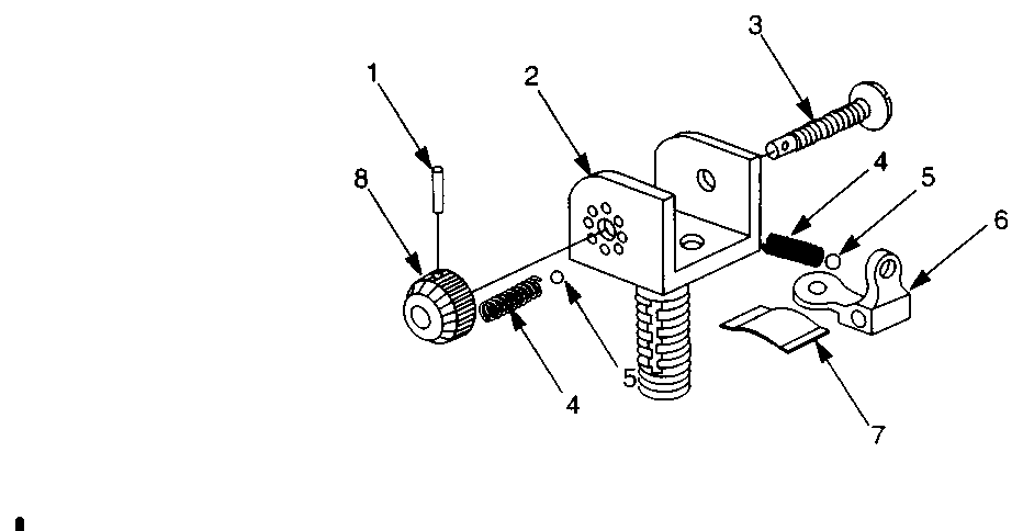
- Drive out the windage knob spring pin with a hammer and 1/16-inch punch.WarningBe sure to catch the small parts.Removed at this step:
Spring pin - Catch the rear sight windage knob, helical spring and ball bearing.Removed at this step:
Windage knobHelical springBall bearing - Remove the rear sight windage screw with a flat-bladed screwdriver.Removed at this step:
Windage screw - Remove the sight aperture and flat spring from the upper receiver.Removed at this step:
Sight apertureFlat spring - Drive out the elevation spring pin with a 3/32-inch punch and catch the helical spring as the punch is withdrawn.WarningTo avoid injury to your eyes, use care when removing and installing spring-loaded parts.Removed at this step:
Spring pinHelical spring - Rotate the elevation index until the rear sight base clears the upper receiver, catching the ball bearing and helical spring as it clears.Removed at this step:
Rear sight baseBall bearingHelical spring - Push the elevation index out with your thumb using a slight rotating motion, and catch the ball bearing and helical spring.Removed at this step:
Elevation knob assemblyBall bearingHelical spring - Remove the index screw with a 1/16-inch Allen wrench, discard it, and separate the elevation index from the elevation knob by hand.Removed at this step:
Index screwElevation indexElevation knob - Remove the forward assist spring pin with a 3/32-inch drive pin punch and hand hammer.Removed at this step:
Pin - Remove the forward assist assembly and its helical spring from the upper receiver.WarningTo avoid injury to your eyes, use care when removing and installing spring-loaded parts.Removed at this step:
Forward assist assemblyHelical spring
Disassemble the forward assist
Detail Strip tools required gunsmith recommendedTM 9-1005-319-23&P para 3-12a, after the forward assist is out of the upper receiver. Direct support maintenance (chapter 3).
Applies to: Upper receivers with a forward assist.
Follows TM 9-1005-319-23&P (Air Force TO 11W3-5-5-42), Unit and Direct Support Maintenance Manual incl. RPSTL: Rifle, 5.56 mm, M16A2; Carbine, 5.56 mm, M4/M4A1 (with Changes 1-5) — Headquarters, Department of the Army / Department of the Air Force, para 3-12a (p. 3-59) archive.org [5]
- Drive out the spring pin with a 1/16-inch drive pin punch and hand hammer.WarningTo avoid injury to your eyes, use care when removing and installing spring-loaded parts.Removed at this step:
Spring pin - Remove the forward assist pawl, pawl detent and helical spring from the plunger assembly.Removed at this step:
Forward assist pawlPawl detentHelical spring
Install the pivot pin, takedown pin, buttstock and pistol grip
Detail Reassembly tools required gunsmith recommendedTM 9-1005-319-23&P para 2-17f, steps 2–8. The TM's step 1 (buffer and action spring) is in the entry's 'buffer-removal' procedure. Unit maintenance (chapter 2) — above operator level.
Follows TM 9-1005-319-23&P (Air Force TO 11W3-5-5-42), Unit and Direct Support Maintenance Manual incl. RPSTL: Rifle, 5.56 mm, M16A2; Carbine, 5.56 mm, M4/M4A1 (with Changes 1-5) — Headquarters, Department of the Army / Department of the Air Force, para 2-17f (pp. 2-62 to 2-64) archive.org [5]
- Install the fabricated pivot pin installation tool, insert the helical spring and pivot pin detent, compress the detent into its recess with a 3/32-inch punch and rotate the tool, then remove the punch.WarningTo avoid injury to your eyes, use care when removing and installing spring-loaded parts.
- Install the pivot pin while removing the installation tool, keeping pressure on the pin as it slides into the hole, and rotate the pivot pin until the detent enters its groove.TipThe rounded end of the pivot pin detent must be in the groove of the pivot pin when assembly is complete.
- Fixed rifle stock: install the takedown pin with its groove toward the rear, then install the takedown pin detent and helical spring from the rear.WarningDo not kink the helical spring during assembly.
- Fixed rifle stock: install the stepped spacer on the receiver extension and carefully slide the buttstock assembly on to compress the helical spring.
- Fixed rifle stock: secure the buttstock assembly with a new self-locking screw.
- Collapsible carbine stock: grasp the lock release lever near the retaining nut, pull, and slide the buttstock assembly onto the lower receiver extension.
- Install the safety detent, pointed end first, and its helical spring into the bottom of the lower receiver.WarningDo not kink the helical spring during assembly.
- Carefully install the pistol grip so that it compresses the helical spring, and secure it with the lockwasher and screw.WarningWith the enhanced rifle grip (PN 9349127), the TM authorizes only a 1-1/8 in. or 1 in. grip screw; any screw longer than 1-1/8 in. could cause a hazardous situation. Make sure the washer is in place.TipPart of the helical spring fits into a hole in the pistol grip.
Install the trigger, hammer, selector, magazine catch and bolt catch
Detail Reassembly tools required gunsmith recommendedTM 9-1005-249-23&P para 3-16g, the semiautomatic parts only. Direct support maintenance (chapter 3).
Follows TM 9-1005-249-23&P Unit and Direct Support Maintenance Manual (Including Repair Parts and Special Tools List): Rifle, 5.56mm, M16 and M16A1 — Departments of the Army and Air Force; Commandant, Coast Guard, para 3-16g (pp. 3-58 to 3-60) archive.org [11]
- Install the trigger assembly and disconnector into the lower receiver.
- Install the trigger pin with a drive pin punch, pushing it in until flush.
- Install the hammer assembly with the ends of the hammer spring to the rear of the trigger pin, resting in the annular groove on the upper surface of the trigger pin.
- Install the hammer pin with a drive pin punch, pushing it in until flush.
- Install the safety selector lever.TipTM 9-1005-319-23&P (p. 3-71): the hammer should be cocked before the selector lever is installed. At this point the military rifle has an additional part that the semiautomatic AR-15 does not have; it is not covered here.
- Install the magazine catch spring and magazine button.WarningTo avoid injury to your eyes, use care when removing and installing spring-loaded parts.
- Push in on the magazine button with a drive pin punch and turn the magazine catch clockwise until its threaded end is flush with the magazine button head.TipTM 9-1005-319-23&P: the punch should be larger than the hole in the magazine button.
- Install the bolt catch spring, bolt catch plunger and bolt catch.
- Secure the bolt catch by installing the spring pin with a 3/32-inch drive pin punch and hand hammer.
- Install the pistol grip and buttstock (procedure 'lower-receiver-grip-stock-pins-installation'), then function check the rifle.TipTM 9-1005-249-23&P para 3-20: with the selector on semi, the hammer must not fall with 5.5 lb on the trigger and must fall by 8.5 lb.
Install the hammer and trigger springs
Detail Reassembly gunsmith recommendedTM 9-1005-249-23&P paras 3-17c and 3-18c. Direct support maintenance (chapter 3).
Follows TM 9-1005-249-23&P Unit and Direct Support Maintenance Manual (Including Repair Parts and Special Tools List): Rifle, 5.56mm, M16 and M16A1 — Departments of the Army and Air Force; Commandant, Coast Guard, para 3-18c (p. 3-62) archive.org [11]
- Install the hammer spring on the hammer.
- Install the disconnector spring by inserting the large end of the spring into the trigger.
- Install the trigger spring on the trigger.
Install the lower receiver extension and trigger guard
Detail Reassembly tools required gunsmith recommendedTM 9-1005-319-23&P para 3-16d. The torque values (rifle extension 35–39 ft-lb; carbine locking nut 40 ±2 in-lb) are already in the entry's torqueSpecs. Direct support maintenance (chapter 3).
Follows TM 9-1005-319-23&P (Air Force TO 11W3-5-5-42), Unit and Direct Support Maintenance Manual incl. RPSTL: Rifle, 5.56 mm, M16A2; Carbine, 5.56 mm, M4/M4A1 (with Changes 1-5) — Headquarters, Department of the Army / Department of the Air Force, para 3-16d (pp. 3-80 to 3-82) archive.org [5]
- Fixed rifle stock: install the helical spring and buffer retainer into the lower receiver.WarningTo avoid injury to your eyes, use care when removing and installing spring-loaded parts.
- Fixed rifle stock: lubricate the threads of the lower receiver and lower receiver extension with molybdenum disulfide grease.
- Fixed rifle stock: install the lower receiver extension into the lower receiver while depressing the buffer retainer.
- Fixed rifle stock: clamp the solid portion of the lower receiver in padded, conforming vise jaws and torque the extension with the combination wrench and torque wrench, reading torque with both wrenches used together.
- Carbine: lubricate the threads of the lower receiver and extension with molybdenum disulfide grease.
- Carbine: pre-position the spring and buffer retainer in the lower receiver, and screw the locking nut onto the extension with its three notches facing forward.
- Carbine: fit the receiver end plate onto the extension with its lug facing forward.
- Carbine: pre-position the takedown pin, detent and spring in the lower receiver.
- Carbine: push down on the buffer retainer and spring and screw the extension in until it retains the buffer retainer.
- Carbine: align the end plate lug into the rear of the lower receiver and screw the locking nut forward until it contacts the end plate.
- Carbine: tighten the locking nut snug with the special tool, then torque it with the special tool and a torque wrench.
- Carbine: stake the receiver end plate in two places across from the notches in the locking nut.
- Install the trigger guard into the lower receiver.
- Install the trigger guard spring pin with a 1/8-inch drive pin punch and hand hammer.
Install the ejection port cover, sling swivel, front sight post and handguards
Detail Reassembly tools required gunsmith recommendedTM 9-1005-319-23&P para 2-16f. Unit maintenance (chapter 2) — above operator level.
Follows TM 9-1005-319-23&P (Air Force TO 11W3-5-5-42), Unit and Direct Support Maintenance Manual incl. RPSTL: Rifle, 5.56 mm, M16A2; Carbine, 5.56 mm, M4/M4A1 (with Changes 1-5) — Headquarters, Department of the Army / Department of the Air Force, para 2-16f (pp. 2-52 to 2-56) archive.org [5]
- Position the ejection port cover and helical spring on the upper receiver, with the short leg of the spring to the rear on the inside of the cover.
- Hold the spring's short leg in place and turn the long leg one half turn (180 degrees) with your fingers.
- Position the long leg against the ejection port cover, hold spring and cover in place, and install the headless grooved pin, checking spring tension as you install the retaining ring.
- Rifle: position the small sling swivel and install a new tubular rivet, spreading and flaring its hollow head with a center punch and hammer.
- Carbine: install the front swivel to the swivel mount with a new rivet, flaring it with a center punch and hammer; install the swivel mount, place the swivel locking bar in it and install the two spring pins.TipThe TM recommends the mount on the left for right-handed shooters and on the right for left-handed shooters.
- Position the helical spring and front sight detent in the front sight.
- Install the front sight post by turning the removal and installation tool clockwise until the post's base is flush with or slightly below the front sight frame.WarningTo avoid injury to your eyes, use care when removing and installing spring-loaded parts.
- Install the top of the upper handguard assembly in the tube cap while pushing down on the handguard slip ring, push the bottom of the handguard into place and release the slip ring.
- Install the lower handguard assembly the same way, then release the slip ring to lock both handguards.
Install the barrel, compensator and gas tube
Detail Reassembly tools required gunsmith recommendedTM 9-1005-319-23&P para 3-10d–e. The barrel nut (30 ft-lb three times, 80 ft-lb ceiling) and compensator (15–20 ft-lb) torques are already in the entry's torqueSpecs. After a barrel change the TM requires a headspace check, test firing and re-zeroing. Direct support maintenance (chapter 3).
Follows TM 9-1005-319-23&P (Air Force TO 11W3-5-5-42), Unit and Direct Support Maintenance Manual incl. RPSTL: Rifle, 5.56 mm, M16A2; Carbine, 5.56 mm, M4/M4A1 (with Changes 1-5) — Headquarters, Department of the Army / Department of the Air Force, para 3-10d (pp. 3-39 to 3-45) archive.org [5]
- Slide the barrel nut to the rear of the barrel assembly as far as it will go.
- Slide the handguard slip ring over the barrel nut.
- Press the slip ring spring from both sides and insert it into the handguard slip ring.
- Install the retaining ring against the slip ring spring with retaining ring pliers and snap it onto the barrel nut.
- Apply molybdenum disulfide grease to the barrel nut threads.
- Position the barrel assembly with its alignment pin up and clamp it in the vise using the barrel remover fixture.TipThe alignment pin must not show any looseness.
- Align the slot in the upper receiver with the barrel's alignment pin and install the upper receiver over the end of the barrel.TipThe slot should fit the pin with very little or no rotational play.
- Wipe the upper receiver threads clean, check for burrs, and apply molybdenum disulfide grease to them.
- Engage the barrel nut threads with the upper receiver.
- Torque the barrel nut with the combination wrench and torque wrench, then loosen it, torque it again, and loosen it again.WarningMake certain all three drive pins of the combination wrench are engaged. Do not use the torque wrench for loosening.
- With the front sight post installed, align the bore on a distant vertical target and check that the front sight post is on line and vertical with it; adjust rear sight windage for a proper sight picture.TipIf excessive windage is needed, the barrel's alignment pin does not fit the receiver slot properly and the upper receiver must be replaced.
- Torque the barrel nut a third time while maintaining sight alignment, tightening further only as needed to bring a serration in line for gas tube clearance.WarningNever loosen the barrel nut to align it for gas tube clearance, and do not exceed the TM's maximum when tightening to the next hole.
- Check barrel nut alignment by passing the front 8 inches of a gas tube (or a No. 15 drill) through the carrier key and the rear of the receiver; it must pass freely and lie top dead center along the barrel.
- Install the peel washer, thin sections to the rear, and the compensator on the barrel.
- Torque the compensator with the combination wrench and torque wrench so that part of the third (middle) slot opening is straight up in line with the front sight post, removing or adding peel washer sections as required.
- Slide the gas tube through the barrel nut assembly and forward into the hole in the front sight assembly base, and align the holes in the gas tube and the base.
- Drive the spring pin into the front sight assembly base with a ball-peen hammer and 5/64-inch drive pin punch to secure the gas tube.
- Install the upper and lower handguard assemblies.
- Check headspace with the headspace gage before returning the rifle to service.WarningHeadspace is checked with the TM's gage and procedure (para 3-10e). After rebarreling, the TM requires function firing and targeting the rifle.
Install the forward assist and the A2 rear sight
Detail Reassembly tools required gunsmith recommendedTM 9-1005-319-23&P para 3-11e, including setting elevation and checking the 300 m zero mark. Direct support maintenance (chapter 3).
Applies to: Upper receivers with the fixed carrying handle and A2 rear sight (M16A2 / A2-pattern AR-15).
Follows TM 9-1005-319-23&P (Air Force TO 11W3-5-5-42), Unit and Direct Support Maintenance Manual incl. RPSTL: Rifle, 5.56 mm, M16A2; Carbine, 5.56 mm, M4/M4A1 (with Changes 1-5) — Headquarters, Department of the Army / Department of the Air Force, para 3-11e (pp. 3-54 to 3-57) archive.org [5]
- Apply CLP to the helical spring and forward assist assembly and install them in the upper receiver.WarningTo avoid injury to your eyes, use care when removing and installing spring-loaded parts.
- Install the forward assist spring pin with a 3/32-inch drive pin punch and hand hammer.
- Assemble the elevation knob and elevation index with a new index screw and a 1/16-inch Allen wrench.WarningDo not overtighten the index screw; the scale will need adjustment.
- Install the ball bearing and helical spring with needle nose pliers or tweezers.
- Depress the ball bearing with a punch through the access hole and slide the elevation knob assembly into the upper receiver from the side, centering it.
- Insert the threaded portion of the rear sight base into the upper receiver and rotate the elevation knob assembly until the threads engage.TipAll three springs are identical when new; if their lengths now differ, use the longest in the windage knob and the shortest under the elevation knob ball.
- Insert the helical spring and ball bearing in their hole as the rear sight base is lowered, rotate until the base is all the way down, then come up 22 clicks.
- Insert the helical spring through the underside of the upper receiver, compress it with a small screwdriver and install the spring pin, then rotate the elevation knob until the rear sight base is all the way down.WarningThe spring pin must pass over the helical spring, not through its coils.
- Install the flat spring and sight aperture in the rear sight base and install the windage screw with a screwdriver.
- Insert the helical spring and ball bearing into the windage knob.TipTilt the upper receiver toward the windage knob to keep from losing the ball bearing.
- Position the windage knob on the windage screw shaft, align the holes with a small screwdriver or punch, and install the spring pin.
- Rotate the elevation index and windage knob to check they work freely.
- Check the elevation zero: with the sight bottomed on its last whole click, the 300 m mark must align with the mark on the receiver; if not, loosen the index screw three turns, rotate the lower knob counterclockwise to its stop, and retighten the index screw.
Reassemble the forward assist
Detail Reassembly tools required gunsmith recommendedTM 9-1005-319-23&P para 3-12e. Direct support maintenance (chapter 3).
Applies to: Upper receivers with a forward assist.
Follows TM 9-1005-319-23&P (Air Force TO 11W3-5-5-42), Unit and Direct Support Maintenance Manual incl. RPSTL: Rifle, 5.56 mm, M16A2; Carbine, 5.56 mm, M4/M4A1 (with Changes 1-5) — Headquarters, Department of the Army / Department of the Air Force, para 3-12e (p. 3-61) archive.org [5]
- Lubricate the helical spring, pawl detent and forward assist pawl with CLP.
- Install the helical spring, pawl detent and forward assist pawl into the plunger assembly.WarningTo avoid injury to your eyes, use care when removing and installing spring-loaded parts.
- Align the holes and install the spring pin with a 1/16-inch drive pin punch and hand hammer, flush or slightly below flush.
Reassembly
Reassembly- Insert the bolt into the carrier with the extractor on the same side as the ejection port when the carrier is oriented normally.
- Push the bolt fully into the carrier, drop the cam pin into its hole, and rotate it 90 degrees so it lies across the carrier.WarningIf the cam pin is not rotated, the firing pin will not seat. Never force the firing pin.
- Drop the firing pin into the rear of the carrier, tail first, and let it seat fully.
- Install the firing pin retaining pin. If it will not go in, the cam pin is not installed or not rotated — stop and correct it.WarningThis is the design's built-in check. Do not defeat it.
- Insert the charging handle into its channel in the upper receiver and push it partway forward, leaving it slightly open.
- Insert the bolt carrier group into the charging handle's rear track, with the bolt extended forward, and slide both fully home.
- Mate the upper receiver to the lower, press the front pivot pin home, close the receivers, and press the rear takedown pin home.
- Charge the rifle and perform the function check.
Diagrams
public domainThese are reproduced from government technical manuals, which are not subject to copyright. Manufacturer manual diagrams are not reproduced here — the entry links to the manual instead.
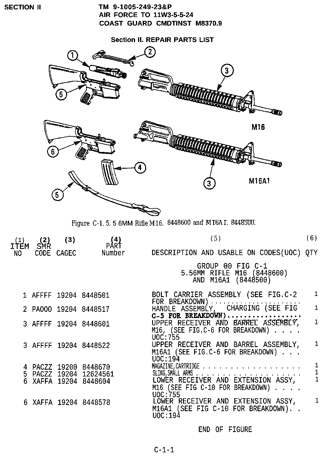
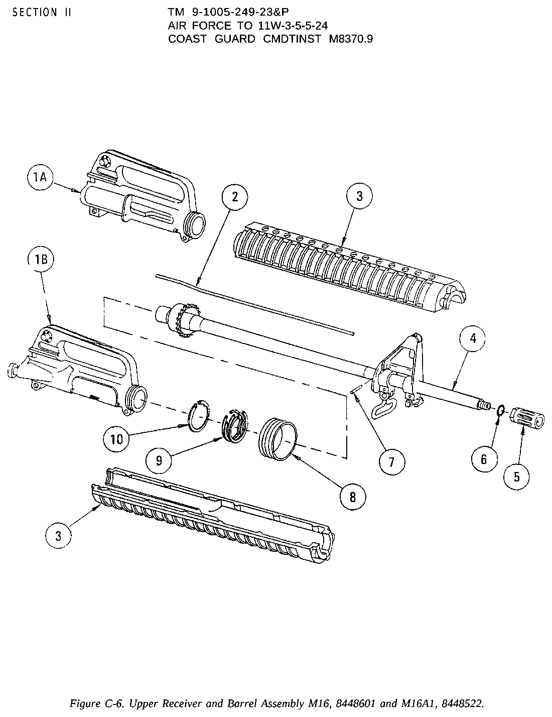
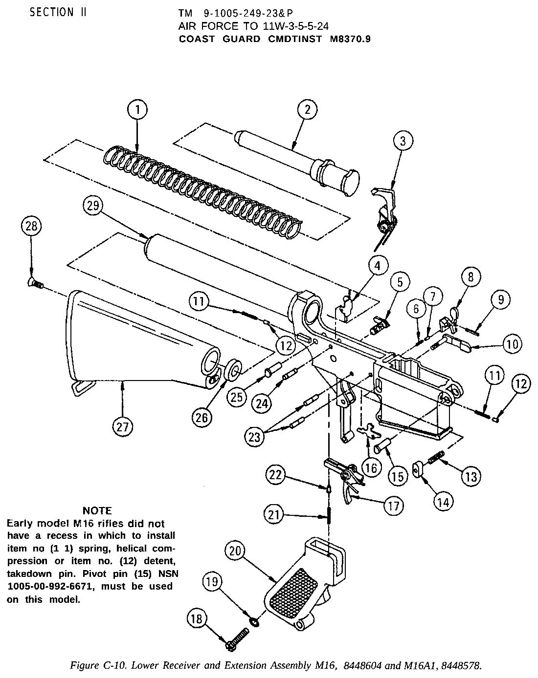
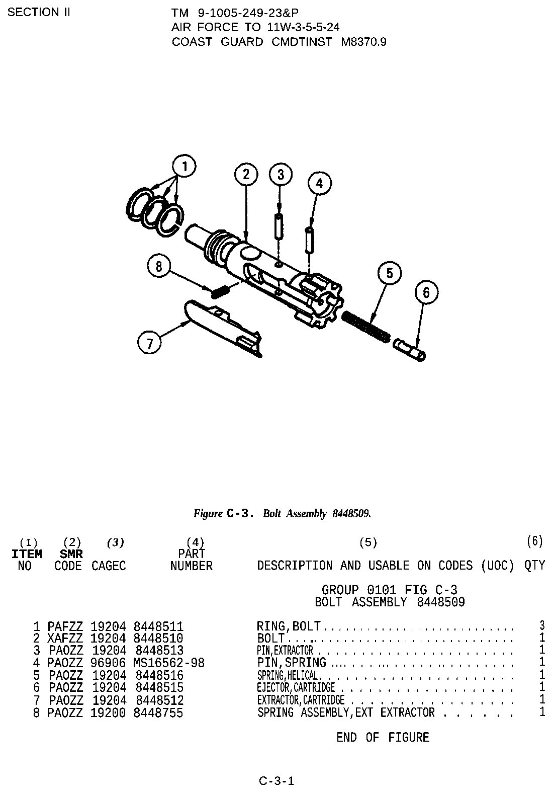
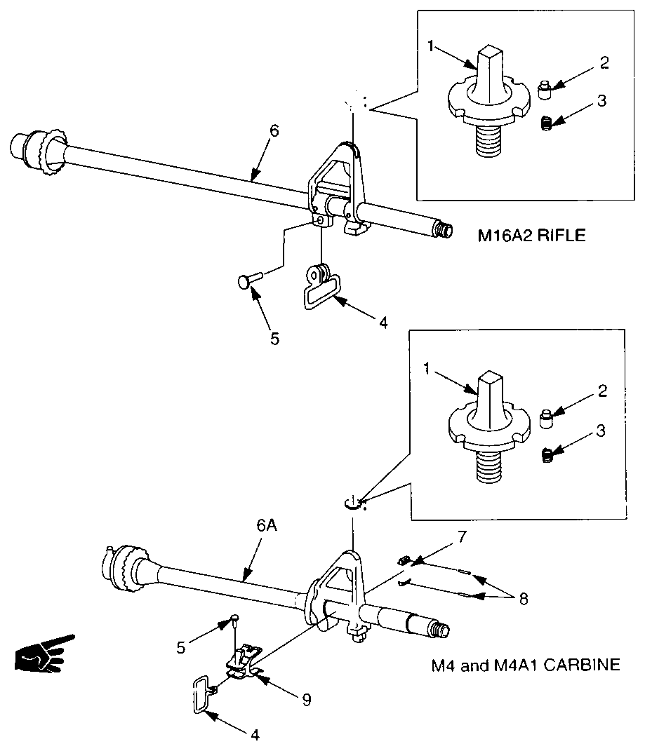
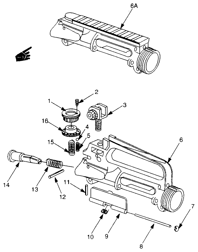
Torque specifications
| Fastener | Torque | Sequence, notes and the source's words | Where it comes from |
|---|---|---|---|
| Barrel nut — seating torque Mil-spec pattern barrel nut (delta-ring type) |
30 ft-lb 40.7 N·m · 360 in-lb |
Engage the barrel nut threads with the upper receiver. With the combination wrench's three drive pins fully engaged and the torque wrench read with both wrenches together, torque to 30 ft-lb, loosen, repeat, loosen again, then torque a third time to 30 ft-lb while keeping sight alignment. The TM: two-time torquing (three times total) gives a better thread fit and keeps barrel nuts from loosening. Never use the torque wrench to loosen. “Using combination wrench (9) and torque wrench, torque barrel nut assembly (8) to 30 ft-lb.” |
TM 9-1005-249-23&P — Unit and Direct Support Maintenance Manual, Rifle, 5.56mm, M16 and M16A1 — Headquarters, Department of the Army, p. 3-31 archive.org [4] |
| Barrel nut — ceiling when aligning for the gas tube Mil-spec pattern barrel nut (delta-ring type) |
max. 80 ft-lb 108.5 N·m · 960 in-lb |
After the third 30 ft-lb torque, the nut may be tightened beyond 30 ft-lb to bring the next serration in line with the gas tube hole. Never loosen the barrel nut to align it — tighten to the next hole instead, and not past this ceiling. “Do not torque over 80 ft-lb while tightening the barrel nut to next hole, to allow for proper alignment.” |
TM 9-1005-249-23&P — Unit and Direct Support Maintenance Manual, Rifle, 5.56mm, M16 and M16A1 — Headquarters, Department of the Army, p. 3-33 archive.org [4] |
| Flash suppressor M16/M16A1 flash suppressor |
15–20 ft-lb 20.3–27.1 N·m · 180–240 in-lb |
Torque is measured with both wrenches used together. “Torque flash suppressor (15) to 15-20 ft-lb using combination wrench (9) and torque wrench.” |
TM 9-1005-249-23&P — Unit and Direct Support Maintenance Manual, Rifle, 5.56mm, M16 and M16A1 — Headquarters, Department of the Army, p. 3-34 archive.org [4] |
| Carrier key screws (2) | 35–40 in-lb 4–4.5 N·m · 2.9–3.3 ft-lb |
Hold the carrier in a machinist's vise with jaw caps. Do not reuse old screws. The screws are staked afterwards; the TM also says not to retorque screws whose staking marks show no loosening. “Use a socket head screw wrench attachment and torque wrench to torque the carrier and key screws (3) to 35 to 40 inch-pounds.” |
TM 9-1005-249-23&P — Unit and Direct Support Maintenance Manual, Rifle, 5.56mm, M16 and M16A1 — Headquarters, Department of the Army, p. 3-20 archive.org [4] |
| Lower receiver extension (buffer tube) Fixed rifle-stock receiver extension (M16/M16A1) |
35–39 ft-lb 47.5–52.9 N·m · 420–468 in-lb |
Clamp the solid portion of the lower receiver and extension assembly in a vise, with wooden jaws if available. Torque is read with both wrenches used together. “Using combination wrench 11010033 (6) and torque wrench, torque lower receiver extension to 35-39 ft-lb.” |
TM 9-1005-249-23&P — Unit and Direct Support Maintenance Manual, Rifle, 5.56mm, M16 and M16A1 — Headquarters, Department of the Army, p. 3-67 archive.org [4] |
| Receiver end plate locking nut (castle nut) on lower receiver extension M4/M4A1 carbine (TM section headed 'CARBINE ONLY'); tolerance ±2 in-lb per source |
40 in-lb 4.5 N·m · 3.3 ft-lb |
6A. Lubricate threads of lower receiver and extension with molybdenum disulfide grease. 6B. Screw locking nut onto the extension, three notches facing forward. 6C. Align receiver end plate lug forward. 6E. Screw extension in until it retains the buffer retainer. 6F. Screw the locking nut forward until it contacts the receiver end plate. 6G. Tighten the locking nut until snug with the special tool. 6H. Torque to 40 ±2 inch pounds. 6J. Stake the receiver end plate in 2 places across from the notches in the locking nut. “6H. Using the special tool (item 12, app C), and torque wrench, torque locking nut (5.5) to 40 ±2 inch pounds.” |
TM 9-1005-319-23&P (Air Force TO 11W3-5-5-42), Unit and Direct Support Maintenance Manual incl. RPSTL: Rifle, 5.56 mm, M16A2; Carbine, 5.56 mm, M4/M4A1 (with Changes 1-5) — Headquarters, Department of the Army / Department of the Air Force, p. 3-81.1, Change 3 (PDF p. 200) archive.org [5] |
| Compensator (muzzle device) M16A2 rifle / M4-series (TM 9-1005-319-23&P), compensator with peel washer |
15–20 ft-lb 20.3–27.1 N·m · 180–240 in-lb |
14. Install peel washer and compensator on rifle barrel assembly. 15. Torque compensator to 15-20 ft-lb using combination wrench and torque wrench (torque measured when both wrenches are used together). Some portion of the opening of the third or middle slot must be straight up (align with the front sight post) at proper torque level. Thin sections of the peel washer may be removed or added as required. “Torque compensator (12) to 15-20 ft-lb (20-27 N-m) using combination wrench (10) and torque wrench. Torque is measured when both wrenches are used together.” |
TM 9-1005-319-23&P (Air Force TO 11W3-5-5-42), Unit and Direct Support Maintenance Manual incl. RPSTL: Rifle, 5.56 mm, M16A2; Carbine, 5.56 mm, M4/M4A1 (with Changes 1-5) — Headquarters, Department of the Army / Department of the Air Force, p. 3-44, Change 4 (PDF p. 158) archive.org [5] |
Notes: From the US Army's unit and direct support maintenance manual for the M16 and M16A1, TM 9-1005-249-23&P — a primary source for the military rifle this pattern comes from, and armorer-level work. These values are for mil-spec pattern parts: the delta-ring barrel nut with gas-tube alignment, the M16/M16A1 flash suppressor, and the fixed rifle-stock receiver extension. Many commercial AR-15s use free-float handguards whose barrel nuts are proprietary and have their own values from the handguard maker, and carbine receiver extensions with a castle nut are not covered here. Use the values for the parts actually on the rifle. The TM also carries a generic torque table for unspecified fasteners (appendix F); it is not reproduced, because it is not specific to any part of this rifle.
Reported by other sources — not the manufacturer
| Fastener | Torque | Who says so, and their words | Where it comes from |
|---|---|---|---|
| Receiver extension lock (castle) nut AR15/M4 carbine receiver extension, when fitting Magpul's ASAP end plate |
40 ft-lb 54.2 N·m · 480 in-lb |
Reported by Magpul Industries Screw the receiver extension in while holding the end plate and buffer retaining pin; install the locking key; hand tighten the locking nut, then torque. Source states a tolerance of ± 2 foot lbs. Threadlocker: DO NOT USE LOCTITE® OR OTHER LOCKING COMPOUND ON RECEIVER EXTENSION THREADS. “With the armorers/spanner wrench, tighten the locking nut down to 40 ± 2 foot lbs. torque per US Army TM 9-1005-319-23&P Unit and Direct Support Maintenance Manual (3-81.1).” |
ASAP (Ambidextrous Sling Attachment Point) Installation Instructions — Magpul Industries, PDF p. 1 magpul.com [6] |
| Barrel nut (Geissele aluminium barrel nut supplied with the SMR MK8 handguard) AR-15/M4 mil-spec flat-top upper fitted with a Geissele SMR MK8 M-LOK handguard |
40 ft-lb 54.2 N·m · 480 in-lb |
Reported by Geissele Automatics (document hosted by MidwayUSA) Liberally coat the upper receiver threads and the outer face (torque shoulder) of the barrel extension with anti-seize or grease; hand tighten the Geissele barrel nut, then torque with the Geissele wrench. “Use the Geissele barrel nut wrench to tighten the Geissele barrel nut to 40 ft-lbs by using the pin and corresponding hole in the OD of the barrel nut.” |
Installation Instructions — Geissele Super Modular Rail, MK8 Magpul M-LOK Rails — Geissele Automatics (document hosted by MidwayUSA), PDF p. 1 media.midwayusa.com [7] |
| Handguard (rail) mounting/clamp bolts (2) Geissele SMR MK8 M-LOK handguard on AR-15/M4 |
5 ft-lb 6.8 N·m · 60 in-lb |
Reported by Geissele Automatics (document hosted by MidwayUSA) Keep the scope mount installed during the tightening process. If a torque wrench is not available use a short arm allen key and tighten snug. “Tighten the two rail mounting bolts to 5.0 ft-lbf.” |
Installation Instructions — Geissele Super Modular Rail, MK8 Magpul M-LOK Rails — Geissele Automatics (document hosted by MidwayUSA), PDF p. 1 media.midwayusa.com [7] |
| Barrel nut (Midwest Industries free-float handguard barrel nut) AR-15 fitted with a Midwest Industries free-float M-LOK handguard |
40 ft-lb 54.2 N·m · 480 in-lb |
Reported by Midwest Industries, Inc. “Set your torque wrench to 40 ft/lbs. Hold the barrel nut wrench tightly against the barrel nut and torque to 40 ft/lbs.” |
Free Float Hand Guard Installation Instructions — Midwest Industries, Inc., PDF p. 1 midwestindustriesinc.com [8] |
| Handguard clamp screws, 10-32 x ½" socket head (with MI torque plate) Midwest Industries free-float handguard on AR-15 |
40 in-lb 4.5 N·m · 3.3 ft-lb |
Reported by Midwest Industries, Inc. Drop the torque plate into the slot, finger tighten the bolts, torque, then check receiver/handguard rail alignment. “Torque the 10-32 x ½” socket head cap screw to 40 in/lbs.” |
Free Float Hand Guard Installation Instructions — Midwest Industries, Inc., PDF p. 1 midwestindustriesinc.com [8] |
| Barrel nut — thread-conditioning passes (BCM KMR barrel nut) Mil-spec direct-impingement AR-15 (.223/5.56) fitted with a BCM KMR-series handguard (KMR-A, MCMR, QRF) |
20–30 ft-lb 27.1–40.7 N·m · 240–360 in-lb |
Reported by Bravo Company MFG (BCM) Torque to 20-30 ft-lbs then loosen; repeat a minimum of 4 times for optimal thread engagement and fit. NEVER use the torque wrench for loosening the barrel nut. Then final-torque to 40-50 ft-lbs. “properly align wrench and torque the KMR barrel nut to 20-30 ft-lbs while applying pressure to the wrench in the direction shown.” |
Installation Manual for BCM KMR Series Handguards (KMR-A, MCMR, QRF), Rev. 4/21 — Bravo Company MFG (BCM), p. 2 bravocompanymfg.com [9] |
| Barrel nut — final installation (BCM KMR barrel nut) Mil-spec direct-impingement AR-15 (.223/5.56) fitted with a BCM KMR-series handguard (KMR-A, MCMR, QRF) |
40–50 ft-lb 54.2–67.8 N·m · 480–600 in-lb |
Reported by Bravo Company MFG (BCM) “Final installation of the KMR barrel nut should be 40-50 ft-lbs.” |
Installation Manual for BCM KMR Series Handguards (KMR-A, MCMR, QRF), Rev. 4/21 — Bravo Company MFG (BCM), p. 2 bravocompanymfg.com [9] |
| Handguard cross bolts (notched and locking) BCM KMR-series handguard on AR-15 |
30–40 in-lb 3.4–4.5 N·m · 2.5–3.3 ft-lb |
Reported by Bravo Company MFG (BCM) Degrease the threaded ends of the cross bolts and apply the supplied thread locker; tighten the notched cross bolt so its notch aligns with the adjacent screw hole, then tighten the locking cross bolt (30-40 in-lbs). NEVER over tighten. Threadlocker: Apply the supplied thread locker to the threaded ends of the cross bolts. “Continue to tighten the notched cross bolt to 30-40 in-lbs. so that the notch in the head aligns with the adjacent screw hole as shown in Figure 4.” |
Installation Manual for BCM KMR Series Handguards (KMR-A, MCMR, QRF), Rev. 4/21 — Bravo Company MFG (BCM), p. 2 bravocompanymfg.com [9] |
| Barrel nut (Aero Precision BAR barrel nut, for Enhanced/Quantum handguards on standard threaded uppers) AR15 standard threaded upper receiver with Aero Precision BAR barrel nut |
30–45 ft-lb 40.7–61 N·m · 360–540 in-lb |
Reported by Aero Precision Apply anti-seize grease to the upper receiver threads. Torque to 30 ft. lbs, remove and re-torque; repeat three times to condition the threads. Use shims to time the gas-tube hole at 12 o'clock; 'Torqueing BAR Barrel Nut over 45 ft. lbs. can result in damage to your barrel nut.' “*Recommended torgue 30-45 ft. lbs.” |
AR15 BAR Barrel Nut Installation — Aero Precision, PDF p. 1 aeroprecisionusa.com [10] |
| Barrel nut (Aero Precision ATLAS taper-lock handguard barrel nut) AR-15 upper receiver with an Aero Precision ATLAS (Aero Taper Lock Attachment System) handguard |
35–60 ft-lb 47.5–81.3 N·m · 420–720 in-lb |
Reported by Aero Precision Coat the upper-receiver threads with anti-seize or grease first; align the nut with the receiver and use shims if needed to reach alignment inside the range. “use the provided barrel nut wrench to torque to 35 – 60ftlbs. Use provided shims if necessary.” |
ATLAS (Aero Taper Lock Attachment System) Installation Instructions — Aero Precision, PDF p. 1, step 2 aeroprecisionusa.com [12] |
| Barrel nut (Aero Precision R-ONE / S-ONE handguard barrel nut) AR15 / M4E1 upper receiver with an Aero Precision ATLAS R-ONE or S-ONE handguard |
35–65 ft-lb 47.5–88.1 N·m · 420–780 in-lb |
Reported by Aero Precision Apply non-graphite anti-seize to the receiver threads; torque with the supplied wrench extension and align a gas-tube notch with the receiver gas-tube hole; if alignment is not reached inside the range, add supplied shims. “Next, you will need to tighten your barrel nut to 35-65 ft lbs. using the supplied wrench extension.” |
Aero Precision Support Center — How to install a R-ONE/S-ONE Handguard (updated 2025-01-09; read via the help centre's Zendesk API) — Aero Precision, p. article body support.aeroprecisionusa.com [13] |
| Barrel nut (Aero Precision MOD 4 steel barrel nut) AR15 (M4E1 threaded or mil-spec AR-15 upper) with an Aero Precision MOD 4 M-LOK handguard |
55 ft-lb 74.6 N·m · 660 in-lb |
Reported by Aero Precision Stated as 55 +/- 5 ft-lb; the MOD 4 nut needs no gas-tube timing. The maker gives 55 ± 5. “Barrel Nut Torque: 55 +/-5 FT LBS” |
MOD 4: 7 Sided M-LOK Handguard — Aero Precision product page — Aero Precision, p. Details > Features aeroprecisionusa.com [14] |
| Handguard screws (Aero Precision MOD 4) AR15 with an Aero Precision MOD 4 M-LOK handguard |
55 in-lb 6.2 N·m · 4.6 ft-lb |
Reported by Aero Precision Stated as 55 +/- 5 in-lb. The maker gives 55 ± 5. “Handguard Screw Torque - 55+/-5 in-lbs” |
MOD 4: 7 Sided M-LOK Handguard — Aero Precision product page — Aero Precision, p. Specifications > Other aeroprecisionusa.com [14] |
| Receiver extension castle nut Aero Precision M4E1 lower receiver (AR15) build |
40 ft-lb 54.2 N·m · 480 in-lb |
Reported by Aero Precision Seat the receiver end plate against the receiver before torquing. “Seat the receiver extension end plate against the upper receiver and tighten your castle nut to 40 ft-lbs” |
Aero Precision Support Center — How to build your M4E1 Lower Receiver (updated 2024-01-24; read via the help centre's Zendesk API) — Aero Precision, p. article body (buffer/stock section) support.aeroprecisionusa.com [15] |
| Barrel nut (Aero Precision C.O.P. barrel nut into the C.O.P. upper receiver) AR-15 carbine / mid-length converted with the Aero Precision AR15 C.O.P. Kit (discontinued 2013 kit with its own upper receiver) |
55 ft-lb 74.6 N·m · 660 in-lb |
Reported by Aero Precision Grease the C.O.P. upper threads lightly; the barrel wrench must be fully seated on the nut lugs. The nut does not need indexing for the gas tube. “Torque the barrel nut onto the upper receiver to 55 ft-lb.” |
Aero Precision C.O.P. Kit Manual (Proof 6, 09/03/2013) — AR15 C.O.P. Kit Assembly Manual — Aero Precision, PDF p. 6 (carbine) and p. 11 (mid-length aeroprecisionusa.com [16] |
| Handguard panel / rail-insert screws (C.O.P. kit, T-25 Torx) AR-15 with the Aero Precision AR15 C.O.P. Kit |
25 in-lb 2.8 N·m · 2.1 ft-lb |
Reported by Aero Precision Lightly tighten all screws, then torque in an alternating pattern. Caution on the same page: do not exceed 40 in-lb (strips the screw holes). “Then torque all screws in an alternating pattern to 25 in-lbs.” |
Aero Precision C.O.P. Kit Manual (Proof 6, 09/03/2013) — AR15 C.O.P. Kit Assembly Manual — Aero Precision, PDF p. 6 and p. 11, Kit Construction ste aeroprecisionusa.com [16] |
| Polymer Picatinny rail-section / accessory fasteners on the handguard AR-15 with a BCM MCMR (M-LOK) handguard |
max. 20 in-lb 2.3 N·m · 1.7 ft-lb |
Reported by Bravo Company MFG (BCM) “Do NOT exceed 20 in/lbs. when securing fasteners on Polymer accessories.” |
BCM MCMR-13 (M-LOK Compatible Modular Rail) — product page — Bravo Company MFG (BCM), p. Description, 'Please note' bravocompanyusa.com [17] |
| Aluminum Picatinny rail-section fasteners on the handguard AR-15 with a BCM MCMR (M-LOK) handguard |
30 in-lb 3.4 N·m · 2.5 ft-lb |
Reported by Bravo Company MFG (BCM) “Aluminum Picatinny rail sections may be torqued to 30 in/lbs.” |
BCM MCMR-13 (M-LOK Compatible Modular Rail) — product page — Bravo Company MFG (BCM), p. Description, 'Please note' bravocompanyusa.com [17] |
| M-LOK rail-section screws on the handguard AR-15 with a Midwest Industries one-piece free-float handguard (same text in MI's CRM-HD instructions) |
15 in-lb 1.7 N·m · 1.2 ft-lb |
Reported by Midwest Industries, Inc. “Install M-Lok rails to the outside of the handguard, torque M-Lok screws to 15 in/lbs.” |
Free Float Hand Guard Installation Instructions — Midwest Industries, Inc., PDF p. 1, step 18 midwestindustriesinc.com [8] |
| Barrel nut (Midwest Industries SP Series barrel nut) AR-15 with a Midwest Industries SP Series handguard |
20 ft-lb 27.1 N·m · 240 in-lb |
Reported by Midwest Industries, Inc. Grease the receiver threads; tighten with the MI wrench to 20 ft-lb 'or until the next gas tube hole aligns'. MI notes the SP nut spec is below the usual AR-15 barrel-nut value. Or until the next gas tube hole aligns with the upper receiver, as the maker says. “Using the provided MI barrel nut wrench, tighten the barrel nut to 20 ft lbs or until the next gas tube hole aligns with the upper receiver.” |
Midwest Industries — SP Series Installation Instructions (AR15) — Midwest Industries, Inc., PDF p. 1, step 8 midwestindustriesinc.com [18] |
| Handguard screws (two-piece extended free-float M-LOK handguard) AR-15 (delta-ring/standard barrel nut) with a Midwest Industries Two Piece Extended Free Float M-Lok Handguard |
25 in-lb 2.8 N·m · 2.1 ft-lb |
Reported by Midwest Industries, Inc. Align the handguard rail with the upper's rail before final torque. “Align the rail on the upper and tighten the screws. Torque the screws to 25 inch lbs.” |
Midwest Industries — Two Piece Extended Free Float M-Lok Handguard Installation Instructions (AR15) — Midwest Industries, Inc., PDF p. 1, step 8 midwestindustriesinc.com [19] |
| Barrel nut (Daniel Defense Bolt-Up System barrel nut) AR-15 (mil-spec flat-top upper) with a Daniel Defense MFR / MFR XL rail (same 55 ft/lbs in DD's DDM4 Rail, SLiM Rail 2019 Rev 1.0 and RIS II instructions) |
55 ft-lb 74.6 N·m · 660 in-lb |
Reported by Daniel Defense, Inc. Bolt-Up Plate first (counter-bored side to the muzzle), then the barrel nut; the plate stays loose after torquing. Install the low-profile gas block and tube before the rail. “Tighten the Bolt-Up System Barrel Nut and torque to 55 ft/lbs using the supplied Daniel Defense Bolt-Up System Barrel Nut Wrench.” |
Daniel Defense MFR / MFR XL Rail (M-LOK) — Installation Instructions, Rev 1.0 (served from www.danieldefense.com; the bare danieldefense.com host returns 403) — Daniel Defense, Inc., PDF p. 1, step 2 danieldefense.com [20] |
| Barrel nut (Daniel Defense Bolt-Up System barrel nut, MFR XS) AR-15 with a Daniel Defense MFR XS rail |
50 ft-lb 67.8 N·m · 600 in-lb |
Reported by Daniel Defense, Inc. The Bolt-Up Plate remains loose after the nut is torqued. “Tighten the Bolt-Up System Barrel Nut and torque to 50 ft/lbs using the supplied Daniel Defense Bolt-Up System Barrel Nut Wrench.” |
Daniel Defense MFR XS Rail — Installation Instructions (served from www.danieldefense.com) — Daniel Defense, Inc., PDF p. 1, step 2 danieldefense.com [21] |
| Rail screws (4) through the Bolt-Up Collar AR-15 with a Daniel Defense MFR, MFR XL (M-LOK or KeyMod) or MFR XS rail |
25–28 in-lb 2.8–3.2 N·m · 2.1–2.3 ft-lb |
Reported by Daniel Defense, Inc. Insert all four screws from the receiver toward the muzzle and tighten in an alternating pattern; without a wrench, a quarter to half turn past first resistance. “If you have an inch/pound torque wrench, the torque specification is 25-28 in/lbs.” |
Daniel Defense MFR / MFR XL Rail (M-LOK) — Installation Instructions, Rev 1.0 (served from www.danieldefense.com; the bare danieldefense.com host returns 403) — Daniel Defense, Inc., PDF p. 1, step 5 danieldefense.com [20] |
| Rail screws (4) through the Bolt-Up Plate AR-15 with a Daniel Defense DDM4 Rail or SLiM Rail |
32 in-lb 3.6 N·m · 2.7 ft-lb |
Reported by Daniel Defense, Inc. Tighten all four screws in an alternating pattern; without a wrench, a quarter to half turn past first resistance. “If you have an inch/pound torque wrench, the torque specification is 32 in/lbs.” |
Daniel Defense DDM4 Rail — Installation Instructions, Rev 1.0 (served from www.danieldefense.com) — Daniel Defense, Inc., PDF p. 1, step 4 danieldefense.com [22] |
| RIS II rail screws (six) through the Bolt-Up Plate AR-15 with a Daniel Defense RIS II rail |
29–32 in-lb 3.3–3.6 N·m · 2.4–2.7 ft-lb |
Reported by Daniel Defense, Inc. Centre screws first, then the bottom screws, then the top screws. “tighten all six screws to 29-32 in/lbs using the supplied allen wrench in the following pattern: the center screws first, the bottom screws next, and the top screws last.” |
Daniel Defense RIS II — Installation Instructions (served from www.danieldefense.com) — Daniel Defense, Inc., PDF p. 3, step 3 danieldefense.com [23] |
| Barrel nut (BATTLEARMS WORKHORSE handguard) Mil-spec AR-15 carbine with a BATTLEARMS WORKHORSE free-float M-LOK handguard w/ ASAL lock |
30–45 ft-lb 40.7–61 N·m · 360–540 in-lb |
Reported by Battle Arms Development, Inc. (BAD / BATTLEARMS) “Barrel Nut 30-45 ft-lbs” |
WORKHORSE 13" Free Float Rail M-LOK Rail Handguard w/ ASAL Lock — BATTLEARMS product page (same 'Installation Torque Recommendations' on the WORKHORSE 4" page) — Battle Arms Development, Inc. (BAD / BATTLEARMS), p. Installation Torque Recommendations battlearmsdevelopment.com [24] |
| Handguard screws (BATTLEARMS WORKHORSE) Mil-spec AR-15 carbine with a BATTLEARMS WORKHORSE free-float M-LOK handguard w/ ASAL lock |
10–15 in-lb 1.1–1.7 N·m · 0.83–1.2 ft-lb |
Reported by Battle Arms Development, Inc. (BAD / BATTLEARMS) “Screws 10-15 in-lbs” |
WORKHORSE 13" Free Float Rail M-LOK Rail Handguard w/ ASAL Lock — BATTLEARMS product page (same 'Installation Torque Recommendations' on the WORKHORSE 4" page) — Battle Arms Development, Inc. (BAD / BATTLEARMS), p. Installation Torque Recommendations battlearmsdevelopment.com [24] |
| Barrel nut — final torque (BATTLEARMS RIGIDRAIL) M16 / M4 / AR-15 with a BATTLEARMS RIGIDRAIL free-float handguard |
45 ft-lb 61 N·m · 540 in-lb |
Reported by Battle Arms Development, Inc. (BAD / BATTLEARMS) After the 40 ft-lb seating pass and loosening one-half turn; ceiling 50 ft-lb. “Loosen the barrel nut one-half turn and re-torque to 45 ft-lbs. (Do not exceed 50 ft-lbs.” |
BATTLEARMS RIGIDRAIL Free Float Rail Handguards for the M16 . M4 . AR-15 or AR-10 Weapon Platforms — Instructions (maker's PDF re-hosted by distributor OpticsPlanet; no copy found on battlearmsdevelopment.com) — Battle Arms Development, Inc. (BAD / BATTLEARMS), PDF p. 2, step 8 opticsplanet.com [25] |
| Rail retention clamp hex bolts (2) (BATTLEARMS RIGIDRAIL) M16 / M4 / AR-15 with a BATTLEARMS RIGIDRAIL free-float handguard |
30 in-lb 3.4 N·m · 2.5 ft-lb |
Reported by Battle Arms Development, Inc. (BAD / BATTLEARMS) Alternate between the two bolts until both stop rotating at the set torque. Threadlocker: Blue Loctite recommended on the hex bolts. “Insert the rail retention clamp into the the RIGIDRAIL™ and tighten the hex bolts to 30 in-lbs.” |
BATTLEARMS RIGIDRAIL Free Float Rail Handguards for the M16 . M4 . AR-15 or AR-10 Weapon Platforms — Instructions (maker's PDF re-hosted by distributor OpticsPlanet; no copy found on battlearmsdevelopment.com) — Battle Arms Development, Inc. (BAD / BATTLEARMS), PDF p. 3, step 13 opticsplanet.com [25] |
| Barrel nut (ODIN Works O2 Lite forend, into the forend adapter) AR-15 with an ODIN Works O2 Lite M-LOK forend |
50 ft-lb 67.8 N·m · 600 in-lb |
Reported by ODIN Works Screw the forend adapter onto the receiver, align its gas-tube hole with the alignment pin, then torque the barrel nut into the adapter. Threadlocker: Vibra-Tite on the barrel nut, per Vibra-Tite instructions. “Torque the barrel nut to 50 ft. lbs.” |
ODIN Works O2 Lite M-LOK Forend (AR-15 > Upper > Forends) — product page, 'Forend Installation Instructions' (same text on the 7" and 9" pages) — ODIN Works, p. Forend Installation Instructions odinworks.com [26] |
| Barrel nut (ODIN Works 223/5.56 forend barrel nut) AR-15 with an ODIN Works 223/5.56 forend (installed with the 1 1/4" jumbo crowfoot) |
40–50 ft-lb 54.2–67.8 N·m · 480–600 in-lb |
Reported by ODIN Works “Use this crowfoot wrench to torque the barrel nut to 40-50 ft lbs” |
ODIN Works 1 1/4" Jumbo Crowfoot Wrench (for ODIN Works 223/5.56 Forend installation) — product page — ODIN Works, p. Features odinworks.com [27] |
| Muzzle device / suppressor mount (ODIN Works OSM 5, 1/2-28) AR15 and variants with 1/2-28 muzzle threads, ODIN Works Suppressor Mount (OSM) 5 |
35 ft-lb 47.5 N·m · 420 in-lb |
Reported by ODIN Works Hand-screw onto the barrel until snug, then torque; no shims or washers. “Tighten down to 35 foot-pounds with a torque wrench” |
ODIN Works Suppressor Mount (OSM) 5 — product page, 'OSM Installation' — ODIN Works, p. OSM Installation odinworks.com [28] |
| Barrel nut (Faxon G3 Streamline handguard) AR15 with a Faxon G3 Streamline Aluminum M-LOK handguard |
35–60 ft-lb 47.5–81.3 N·m · 420–720 in-lb |
Reported by Faxon Firearms 1-3/16" wrench. Faxon: 'DO NOT OVER-TIGHTEN.' “Torque barrel nut to industry specs using 1-3/16” wrench to at least 35ft/lbs but no more than 60ft/lbs.” |
Faxon 15" G3 Streamline Aluminum M-LOK AR15 Handguard — product page 'Installation Instructions' (same text on the 6/7/9/13/17" G3 pages) — Faxon Firearms, p. Installation Instructions faxonfirearms.com [29] |
| Handguard locking-plate bolts (2) (Faxon G3 Streamline) AR15 with a Faxon G3 Streamline Aluminum M-LOK handguard |
32 in-lb 3.6 N·m · 2.7 ft-lb |
Reported by Faxon Firearms Re-check that the bolts are tight after the first live-fire test. “Install locking plate into the recess on the handguard and thread both bolts through the handguard and into the locking plate. Torque bolts to 32 in/lbs.” |
Faxon 15" G3 Streamline Aluminum M-LOK AR15 Handguard — product page 'Installation Instructions' (same text on the 6/7/9/13/17" G3 pages) — Faxon Firearms, p. Installation Instructions faxonfirearms.com [29] |
| Muzzle brake (Faxon MuzzLok Gunner 3-Port 5.56, 1/2x28, MuzzLok timing nut — no crush washer) 5.56/.223 AR barrels threaded 1/2x28 with a Faxon MuzzLok Gunner 3-Port muzzle brake |
20–25 ft-lb 27.1–33.9 N·m · 240–300 in-lb |
Reported by Faxon Firearms Time with the MuzzLok extension nut; no crush washer or shims. “Recommended torque: 20–25 ft-lbs” |
Faxon MuzzLok Gunner 3-Port 5.56 Muzzle Brake – Nitride | 1/2x28 — product page — Faxon Firearms, p. MuzzLok Timing System faxonfirearms.com [30] |
| Ambidextrous safety-selector lever screws (KAK ambi selector) AR-15 lower built with the KAK Basic Ambi Build lower parts kit |
5–7 in-lb 0.56–0.79 N·m · 0.42–0.58 ft-lb |
Reported by KAK Industry De-grease the selector screw threads before assembly; KAK alternatively allows 'hand-tight'. Threadlocker: Blue Loctite on the selector screws. “De-grease ambi selector screw threads and apply blue loctite when assemblying, Tq selector screws to 5-7 in/lbs or hand-tight” |
KAK AR-15 LPK - Basic Ambi Build Kit (AR15-LP-KT-03) — product page (same note on KAK's M16 ambi lower-parts-kit pages) — KAK Industry, p. Description kakindustry.com [31] |
| Barrel nut (AT3 Tactical handguard barrel nut) AR15 with an AT3 Tactical SPEAR M-LOK handguard (identical step in the AT3 Pro Quad Rail instructions, INSTR-QR-01) |
30–60 ft-lb 40.7–81.3 N·m · 360–720 in-lb |
Reported by AT3 Tactical Reinstall gas block and tube after the nut is torqued. “Install the barrel nut and apply 30-60 ft lbs of torque using the provided barrel nut wrench and a torque wrench.” |
AT3 Tactical SPEAR M-LOK Handguard — Installation Instructions (INSTR-SPEAR-03, Rev 3 Oct 18 2021) — AT3 Tactical, PDF p. 1, step 2 media.at3tactical.com [32] |
| Handguard socket-head screws (5/32 hex) (AT3 Tactical) AR15 with an AT3 Tactical SPEAR M-LOK handguard or Pro Quad Rail |
40 in-lb 4.5 N·m · 3.3 ft-lb |
Reported by AT3 Tactical Insert from the left side; AT3's no-wrench alternative is 1/2 turn past hand tight. Then tighten the bottom set screws until they bottom on the barrel nut (no value). “Torque to 40 inch-lbs, or 1/2 turn past hand tight.” |
AT3 Tactical SPEAR M-LOK Handguard — Installation Instructions (INSTR-SPEAR-03, Rev 3 Oct 18 2021) — AT3 Tactical, PDF p. 1, step 4 media.at3tactical.com [32] |
| Stock front QD screw (Magpul PRS GEN3 on a carbine receiver extension) Mil-Spec AR15/M4 carbine receiver extension with a Magpul PRS GEN3 stock |
40 in-lb 4.5 N·m · 3.3 ft-lb |
Reported by Magpul Industries Corp. Front Body Screw only hand tight (1/8" hex). “Torque front QD screw to 40 [in-lb] and front Body Screw until hand tight using 1/8” Hex Wrench.” |
Magpul MAG672 PRS GEN3 Stock — Installation Instructions (072-0115-A) — Magpul Industries Corp., PDF p. 1, Carbine Receiver Extension, st magpul.com [33] |
| Stock front QD screw (Magpul PRS GEN3 on a rifle receiver extension) AR15 rifle-length receiver extension with a Magpul PRS GEN3 stock (rifle adapter cap) |
20 in-lb 2.3 N·m · 1.7 ft-lb |
Reported by Magpul Industries Corp. Front body screw hand tight. “Torque front QD Screw to 20 [in-lb] and front body screw until hand tight using 1/8” Hex Wrench.” |
Magpul MAG672 PRS GEN3 Stock — Installation Instructions (072-0115-A) — Magpul Industries Corp., PDF p. 2, Rifle Receiver Extension, step magpul.com [33] |
| Stock rear body screws (2) when moving the QD footman's loop (Magpul PRS GEN3) AR15 with a Magpul PRS GEN3 stock |
20 in-lb 2.3 N·m · 1.7 ft-lb |
Reported by Magpul Industries Corp. Over-tightening may impede the length-of-pull adjustment knob. “Reinstall in desired location and tighten Screws to 20 [in-lb].” |
Magpul MAG672 PRS GEN3 Stock — Installation Instructions (072-0115-A) — Magpul Industries Corp., PDF p. 2, Reversible QD Footman's Loop magpul.com [33] |
| Receiver extension (Magpul UBR GEN2 buffer tube) into the lower receiver AR15/M4 lower with a Magpul UBR GEN2 stock |
35–39 ft-lb 47.5–52.9 N·m · 420–468 in-lb |
Reported by Magpul Industries Corp. Hold the buffer retaining pin depressed while threading the tube in; use the square recess on the back of the tube with a 1/2" torque driver. Magpul cites US Army TM 9-1005-319-23&P for the value. Threadlocker: None — 'DO NOT USE LOCTITE OR OTHER LOCKING COMPOUND ON RECEIVER EXTENSION THREADS.' “tighten with a ½” torque driver and torque to 35-39 ft-lb.” |
Magpul UBR GEN2 Collapsible Stock — Installation & Usage Instructions for the AR15/M4 & SR25/M110 (072-0105-B) — Magpul Industries Corp., PDF p. 4 magpul.com [34] |
| UBR GEN2 Main Tube Nut AR15/M4 with a Magpul UBR GEN2 stock |
20–25 ft-lb 27.1–33.9 N·m · 240–300 in-lb |
Reported by Magpul Industries Corp. Use the included adapter tool with an armorer's (castle-nut) wrench. “tighten the Main Tube Nut to 20-25 ft-lb.” |
Magpul UBR GEN2 Collapsible Stock — Installation & Usage Instructions for the AR15/M4 & SR25/M110 (072-0105-B) — Magpul Industries Corp., PDF p. 5, step 7 magpul.com [34] |
Function check
- Verify the rifle is unloaded with no magazine inserted before each step.
- Charge the rifle to cock the hammer, then place the selector on SAFE and press the trigger. The hammer must not fall.
- Move the selector to SEMI and press the trigger. The hammer should fall.
- Hold the trigger to the rear, charge the rifle, then release the trigger slowly. You should hear and feel the disconnector release the hammer to the trigger — a distinct click.
- Press the trigger again. The hammer should fall.
- Push the forward assist and confirm the bolt goes fully into battery.
- Insert an empty magazine, charge the rifle, and confirm the bolt locks back on the empty magazine.
Maintenance
Lubrication points
- The eight locking lugs and the bolt body
- The cam pin and its track in the carrier
- The outside of the carrier where it rides in the upper receiver
- The gas rings
- Charging handle rails
- A light film on the hammer and trigger pins
Cleaning notes
A direct-impingement AR runs better wet than dry. Carbon on the bolt tail and inside the carrier is normal and does not all need to be removed — focus on the locking lugs, the gas rings, the chamber, and the bore. Do not scrape carbon off the bolt tail with steel, which can remove material.
Suggested inspection interval: roughly every 1000 rounds. This is a general guideline, not a manufacturer specification.
Wear parts to inspect
Gas rings · Extractor and extractor spring insert · Bolt (inspect the cam pin hole and lugs for cracks) · Buffer spring · Ejector spring · Gas tube alignment
Common issues
| Symptom | Likely cause | What to do |
|---|---|---|
| Firing pin retaining pin will not install | Cam pin missing or not rotated 90 degrees | Remove the firing pin, install and rotate the cam pin, then reinstall. Never force the retaining pin. |
| Charging handle will not come out | Trying to remove it before the bolt carrier group | Remove the carrier first, then pull the charging handle down and out. |
| Short-stroking or failure to lock back on an empty magazine | Worn gas rings, gas leak at the gas block, undersized gas port, or a fouled gas key | Check gas rings first, then gas block alignment and gas key staking. see a gunsmith |
| Bolt will not close fully into battery | Fouled chamber, out-of-spec ammunition, or a dirty bolt | Do not force it with the forward assist on a round you suspect is out of spec. Clear the rifle and inspect the chamber. |
Also covers
The procedures above are reported to apply to: M16A2/A4 · M4 Carbine · Most AR-15 pattern rifles from any manufacturer · AR-pattern pistols and SBRs. Verify against the manual for your specific model.
Similar manual of arms
Legal notes
Sourcing
- Confidence
- high — Cross-checked against a primary source such as the manufacturer's manual or an issuing military technical manual.
- Verification
- Checked against an armorer/technical manual
- Last updated
- 2026-10-29
References
Every source this page draws on, with its web address so you can read it yourself. Numbers in brackets elsewhere on the page point here.
- [1] TM 9-1005-319-10: Rifle, 5.56mm, M16A2/M4 Carbine — U.S. Department of the Army military technical manual primary source
- [2] FM 3-22.9: Rifle Marksmanship M16-/M4-Series Weapons — U.S. Department of the Army military technical manual primary source
- [3] Colt AR-15 Owner's Manual — Colt's Manufacturing Company manufacturer manual primary source
- [4] TM 9-1005-249-23&P — Unit and Direct Support Maintenance Manual, Rifle, 5.56mm, M16 and M16A1 — Headquarters, Department of the Army military technical manual primary source
https://archive.org/details/ArmyTechnicalManualforM16Rifle-Tm9-1005-249-23p (checked 2026-09-27) - [5] TM 9-1005-319-23&P (Air Force TO 11W3-5-5-42), Unit and Direct Support Maintenance Manual incl. RPSTL: Rifle, 5.56 mm, M16A2; Carbine, 5.56 mm, M4/M4A1 (with Changes 1-5) — Headquarters, Department of the Army / Department of the Air Force (1991) military technical manual primary source
https://archive.org/download/milmanual-tm-9-1005-319-23-m16a2-maintenance--repair-manual/tm_9-1005-319-23_m16a2_maintenance__repair_manual.pdf (checked 2026-09-27) - [6] ASAP (Ambidextrous Sling Attachment Point) Installation Instructions — Magpul Industries manufacturer manual secondary source
https://magpul.com/media/wysiwyg/Instructions/MAG500_ASAP_INSRT.pdf (checked 2026-09-27) - [7] Installation Instructions — Geissele Super Modular Rail, MK8 Magpul M-LOK Rails — Geissele Automatics (document hosted by MidwayUSA) manufacturer manual secondary source
https://media.midwayusa.com/productdocuments/instructions/618/installation_geissele_mk8.pdf (checked 2026-09-27) - [8] Free Float Hand Guard Installation Instructions — Midwest Industries, Inc. manufacturer manual secondary source
https://midwestindustriesinc.com/content/installation-instructions/AR15-Free-Float-Handguard-Instructions.pdf (checked 2026-09-27) - [9] Installation Manual for BCM KMR Series Handguards (KMR-A, MCMR, QRF), Rev. 4/21 — Bravo Company MFG (BCM) manufacturer manual secondary source
https://www.bravocompanymfg.com/downloads/kmr_installation_instructions.pdf (checked 2026-09-27) - [10] AR15 BAR Barrel Nut Installation — Aero Precision manufacturer manual secondary source
https://www.aeroprecisionusa.com/media/downloadable/bar-barrel-nut-instructions.pdf (checked 2026-09-27) - [11] TM 9-1005-249-23&P Unit and Direct Support Maintenance Manual (Including Repair Parts and Special Tools List): Rifle, 5.56mm, M16 and M16A1 — Departments of the Army and Air Force; Commandant, Coast Guard (1991) military technical manual primary source
https://archive.org/download/ArmyTechnicalManualforM16Rifle-Tm9-1005-249-23p/Manual-Tm9-1005-249-23p.pdf (checked 2026-10-03) - [12] ATLAS (Aero Taper Lock Attachment System) Installation Instructions — Aero Precision manufacturer manual secondary source
https://www.aeroprecisionusa.com/media/downloadable/ATLAS-install-Instructions.pdf (checked 2026-10-11) - [13] Aero Precision Support Center — How to install a R-ONE/S-ONE Handguard (updated 2025-01-09; read via the help centre's Zendesk API) — Aero Precision website secondary source
https://support.aeroprecisionusa.com/hc/en-us/articles/14130449931671-How-to-install-a-R-ONE-S-ONE-Handguard (checked 2026-10-11) - [14] MOD 4: 7 Sided M-LOK Handguard — Aero Precision product page — Aero Precision website secondary source
https://www.aeroprecisionusa.com/mod-4-m-lok-handguard-pro-lineup (checked 2026-10-11) - [15] Aero Precision Support Center — How to build your M4E1 Lower Receiver (updated 2024-01-24; read via the help centre's Zendesk API) — Aero Precision website secondary source
https://support.aeroprecisionusa.com/hc/en-us/articles/14130428430359-How-to-build-your-M4E1-Lower-Receiver (checked 2026-10-11) - [16] Aero Precision C.O.P. Kit Manual (Proof 6, 09/03/2013) — AR15 C.O.P. Kit Assembly Manual — Aero Precision manufacturer manual secondary source
https://www.aeroprecisionusa.com/media/downloadable/Aero-Precision-COP-Kit-Manual.pdf (checked 2026-10-11) - [17] BCM MCMR-13 (M-LOK Compatible Modular Rail) — product page — Bravo Company MFG (BCM) website secondary source
https://bravocompanyusa.com/bcm-mcmr-13-m-lok-compatible-modular-rail/ (checked 2026-10-11) - [18] Midwest Industries — SP Series Installation Instructions (AR15) — Midwest Industries, Inc. manufacturer manual secondary source
https://midwestindustriesinc.com/content/installation-instructions/AR15-SP-Series-Handguard-Instructions.pdf (checked 2026-10-11) - [19] Midwest Industries — Two Piece Extended Free Float M-Lok Handguard Installation Instructions (AR15) — Midwest Industries, Inc. manufacturer manual secondary source
https://midwestindustriesinc.com/content/installation-instructions/AR15-Two-Piece-Extended-Free-Float-Handguard-M-LOK-Instructions.pdf (checked 2026-10-11) - [20] Daniel Defense MFR / MFR XL Rail (M-LOK) — Installation Instructions, Rev 1.0 (served from www.danieldefense.com; the bare danieldefense.com host returns 403) — Daniel Defense, Inc. manufacturer manual secondary source
https://www.danieldefense.com/media/asset/m/f/mfr_mfrxl_rail_m-lok_instructions.pdf (checked 2026-10-11) - [21] Daniel Defense MFR XS Rail — Installation Instructions (served from www.danieldefense.com) — Daniel Defense, Inc. manufacturer manual secondary source
https://www.danieldefense.com/media/asset/m/f/mfr_xs_rail_installation_instructions.pdf (checked 2026-10-11) - [22] Daniel Defense DDM4 Rail — Installation Instructions, Rev 1.0 (served from www.danieldefense.com) — Daniel Defense, Inc. manufacturer manual secondary source
https://www.danieldefense.com/media/asset/d/d/ddm4_rail_instructions.pdf (checked 2026-10-11) - [23] Daniel Defense RIS II — Installation Instructions (served from www.danieldefense.com) — Daniel Defense, Inc. manufacturer manual secondary source
https://www.danieldefense.com/media/asset/r/i/ris_ii_instructions.pdf (checked 2026-10-11) - [24] WORKHORSE 13" Free Float Rail M-LOK Rail Handguard w/ ASAL Lock — BATTLEARMS product page (same 'Installation Torque Recommendations' on the WORKHORSE 4" page) — Battle Arms Development, Inc. (BAD / BATTLEARMS) website secondary source
https://battlearmsdevelopment.com/shop/bad-wh-hg-mlok-13-workhorse-13-free-float-rail-m-lok-rail-handguard-w-asal-lock-920 (checked 2026-10-11) - [25] BATTLEARMS RIGIDRAIL Free Float Rail Handguards for the M16 . M4 . AR-15 or AR-10 Weapon Platforms — Instructions (maker's PDF re-hosted by distributor OpticsPlanet; no copy found on battlearmsdevelopment.com) — Battle Arms Development, Inc. (BAD / BATTLEARMS) manufacturer manual secondary source
https://www.opticsplanet.com/i/pdf/opplanet-battle-arms-development-rigidrail-ar15-m16-free-float-rail-handguards-installation-pdf.pdf (checked 2026-10-11) - [26] ODIN Works O2 Lite M-LOK Forend (AR-15 > Upper > Forends) — product page, 'Forend Installation Instructions' (same text on the 7" and 9" pages) — ODIN Works website secondary source
https://www.odinworks.com/O2-Lite-M-LOK-Forend-p/f-15-ml-o2.htm (checked 2026-10-11) - [27] ODIN Works 1 1/4" Jumbo Crowfoot Wrench (for ODIN Works 223/5.56 Forend installation) — product page — ODIN Works website secondary source
https://www.odinworks.com/1-1-4-Jumbo-Crow-Foot-Wrench-p/acc-1-1-4-crowfoot-223.htm (checked 2026-10-11) - [28] ODIN Works Suppressor Mount (OSM) 5 — product page, 'OSM Installation' — ODIN Works website secondary source
https://www.odinworks.com/ODIN-Suppressor-Mount-5-p/sup-osm-5.htm (checked 2026-10-11) - [29] Faxon 15" G3 Streamline Aluminum M-LOK AR15 Handguard — product page 'Installation Instructions' (same text on the 6/7/9/13/17" G3 pages) — Faxon Firearms website secondary source
https://faxonfirearms.com/FFHGMLOK15G415 (checked 2026-10-11) - [30] Faxon MuzzLok Gunner 3-Port 5.56 Muzzle Brake – Nitride | 1/2x28 — product page — Faxon Firearms website secondary source
https://faxonfirearms.com/FFMD5563PMBSQPQ (checked 2026-10-11) - [31] KAK AR-15 LPK - Basic Ambi Build Kit (AR15-LP-KT-03) — product page (same note on KAK's M16 ambi lower-parts-kit pages) — KAK Industry website secondary source
https://kakindustry.com/basic-ambi-build-lower-parts-kit (checked 2026-10-11) - [32] AT3 Tactical SPEAR M-LOK Handguard — Installation Instructions (INSTR-SPEAR-03, Rev 3 Oct 18 2021) — AT3 Tactical manufacturer manual secondary source
https://media.at3tactical.com/wp-content/uploads/spear_handguard_instructions_printsize-Rev-3-Oct-18-2021.pdf (checked 2026-10-11) - [33] Magpul MAG672 PRS GEN3 Stock — Installation Instructions (072-0115-A) — Magpul Industries Corp. manufacturer manual secondary source
https://magpul.com/media/wysiwyg/Instructions/MAG672_PRS_GEN3_Stock_INSRT.pdf (checked 2026-10-11) - [34] Magpul UBR GEN2 Collapsible Stock — Installation & Usage Instructions for the AR15/M4 & SR25/M110 (072-0105-B) — Magpul Industries Corp. manufacturer manual secondary source
https://magpul.com/media/wysiwyg/Instructions/MAG482_UBR_GEN2_Stock%20INSRT.pdf (checked 2026-10-11) - [35] AR Lower Receiver Build: Pivot Pin Installation — Shooting Illustrated (NRA) website secondary source
https://www.shootingillustrated.com/content/ar-lower-receiver-build-pivot-pin-installation/ (checked 2026-10-29) - [36] TM 9-1005-249-23&P, Rifle, 5.56mm, M16 and M16A1 (unit and direct support, incl. RPSTL) — Department of the Army military technical manual primary source
https://archive.org/download/ArmyTechnicalManualforM16Rifle-Tm9-1005-249-23p/Manual-Tm9-1005-249-23p_djvu.txt (checked 2026-10-29) - [37] TFB Armorer's Bench: Complete AR15 Assembly - Lower Receiver — The Firearm Blog website secondary source
https://www.thefirearmblog.com/blog/2022/07/31/tfb-armorers-bench-complete-ar15-assembly-lower-receiver/ (checked 2026-10-29)
Notes: Illustrated on 2026-09-14 with figures from TM 9-1005-249-23&P, the US Army maintenance manual for the M16 and M16A1. These are US Government works and therefore public domain, which is why they can be reproduced here. They depict the military rifles; the AR-15's fire control group differs, but the upper receiver, barrel, bolt carrier and bolt are the same parts in the same arrangement. The AR-15 platform spans hundreds of manufacturers. Piston-driven variants, side-charging uppers, and non-standard buffer systems deviate from this procedure — consult the manual for your specific rifle. Buffer removal: the TM note that the hammer must be cocked was added on 2026-10-03.