← All firearms · Printable work order
Benelli M4
- moderate
- Shop tier 2
- medium confidence
- Shotgun
- semi auto shotgun
- gas operated
- dual piston
- duty
- tube magazine
field strip ~4 min · reassembly ~6 min · detail strip ~30 min
Specifications
- Manufacturer
- Benelli Armi
- Origin
- Italy
- Category
- Shotgun
- Action
- Gas, short-stroke piston
- Calibers
- 12 gauge
- Capacity
- 5+1 or 7+1 depending on configuration
- Production
- 1998–present (in-production)
- Also known as
- M1014, M4 Super 90, Benelli M4 Tactical
Model-specific safety
- Unlike most Benellis, the M4 is gas-operated rather than inertia-driven. It uses a self-regulating dual-piston system (ARGO) with two short-stroke pistons in the barrel assembly. Do not apply inertia-gun assumptions to it — there is no inertia spring, and there is a gas system that needs cleaning.
- The gas pistons and cylinders are stainless and self-cleaning to a degree, but they still foul. Carbon buildup there is the usual cause of an M4 that starts short-stroking.
- Unloading a tube magazine takes several cycles. Verify both the chamber and the tube.
- The magazine cap must be fully tight before firing.
Under spring tension
- Recoil spring in the stock tube
- Magazine tube spring
- Hammer spring
Easily lost parts
Gas pistons · Bolt handle · Trigger group pin · Link
Tools
No tools required for the field strip.
Shop difficulty
Shop tier 2 Tier 2 — moderate among shotguns, for the full job: strip to the parts that get coated and put it back together working. More systems than the inertia guns (twin gas pistons and cylinder plugs, rotating bolt with cam pin, link and recoil spring tube in the stock) and the Marine Corps stops operators at field strip, but each step is a single orientation or held-spring trap rather than timing. Top of Tier 2.
No sourced part count yet.
Bench time: about 60 min to strip, 85 min to rebuild (estimate). Strip of bolt (cam pin, firing pin), twin gas pistons and plugs, trigger group, magazine and stock/receiver extension; rebuild longer for pistons, link alignment and magazine spring seal ring.
What comes off for coating
- Barrel / gas: magazine cap, forearm halves, barrel, gas cylinder plugs, two gas pistons (direction noted)
- Magazine: magazine spring seal ring, magazine spring, follower
- Receiver: trigger group locking pin and trigger group, bolt handle, bolt group
- Bolt: firing pin retaining pin, firing pin and spring, cam pin, bolt head, extractor
- Stock: telescoping or fixed stock, pistol grip, recoil spring tube / receiver extension (bare-receiver jobs) — receiver extension wrench
Special tools
- Bolt handle (used as the issued tool) — Gas cylinder plugs and trigger group pin
- 18-19 mm or 1-1/16 in. wrench on the receiver extension flats — Receiver extension removal (bare-receiver jobs)
- Punch set — Bolt pins
Known pain points
- The Marine Corps manual stops operator disassembly at the field strip; anything past that is armorer work. (both)
Source: TM 10698A-10/1 (preliminary): Preliminary TM 10698A-10/1, U.S. Marine Corps Technical Manual: Operator's Manual for Shotgun, Combat, 12 Gauge, Semi-Automatic, M1014 (1005-01-472-3147) [For Official Use Only] — Headquarters, U.S. Marine Corps (Marine Corps Systems Command) archive.org [5] — “Only a trained armorer may proceed beyond this level ofdisassembly.” - The firing pin is pushed in against its spring while the retaining pin is inserted, and the pin must not be pushed fully behind the firing pin. (reassembly)
Source: TM 10698A-10/1 (preliminary): Preliminary TM 10698A-10/1, U.S. Marine Corps Technical Manual: Operator's Manual for Shotgun, Combat, 12 Gauge, Semi-Automatic, M1014 (1005-01-472-3147) [For Official Use Only] — Headquarters, U.S. Marine Corps (Marine Corps Systems Command) archive.org [5] — “Press ın on the back of the firing pin with your finger against spring tension” - The two gas pistons have a front and a back; reversed they will not seal, and both must enter their holes in the receiver as the barrel goes on. (reassembly)
Source: TM 10698A-10/1 (preliminary): Preliminary TM 10698A-10/1, U.S. Marine Corps Technical Manual: Operator's Manual for Shotgun, Combat, 12 Gauge, Semi-Automatic, M1014 (1005-01-472-3147) [For Official Use Only] — Headquarters, U.S. Marine Corps (Marine Corps Systems Command) archive.org [5] — “Install the gas pistons into the gas cylinders with the long extension facing the rear of the barrel” - When the bolt goes back in, the link has to slide over the trigger guard and onto the recoil spring plunger hidden inside the receiver; if it misses, the gun will not cycle and the plunger can be damaged. (reassembly)
Source: M4 Tactical Shotgun Product Manual — Benelli USA / Benelli Armi S.p.A. benelliusa.com [3] — “make sure that the link slides over the trigger guard assembly and onto the recoil spring plunger inside the receiver once the bolt assembly is fully mounted” - The magazine cap and spring seal ring are under considerable spring tension when the magazine is stripped. (both)
Source: TM 10698A-10/1 (preliminary): Preliminary TM 10698A-10/1, U.S. Marine Corps Technical Manual: Operator's Manual for Shotgun, Combat, 12 Gauge, Semi-Automatic, M1014 (1005-01-472-3147) [For Official Use Only] — Headquarters, U.S. Marine Corps (Marine Corps Systems Command) archive.org [5] — “Thecomponents ofthemagazine areunderconsiderable springtension”
Fit or check on rebuild
- Gas pistons installed long extension rearward and entering the receiver holes — Reversed or misaligned pistons will not seal and the gun will not cycle.
Source: TM 10698A-10/1 (preliminary): Preliminary TM 10698A-10/1, U.S. Marine Corps Technical Manual: Operator's Manual for Shotgun, Combat, 12 Gauge, Semi-Automatic, M1014 (1005-01-472-3147) [For Official Use Only] — Headquarters, U.S. Marine Corps (Marine Corps Systems Command) archive.org [5] — “Install the gas pistons into the gas cylinders with the long extension facing the rear of the barrel” - Link aligned with the recoil spring tube — Bolt must move freely; a misaligned link binds.
Source: TM 10698A-10/1 (preliminary): Preliminary TM 10698A-10/1, U.S. Marine Corps Technical Manual: Operator's Manual for Shotgun, Combat, 12 Gauge, Semi-Automatic, M1014 (1005-01-472-3147) [For Official Use Only] — Headquarters, U.S. Marine Corps (Marine Corps Systems Command) archive.org [5] — “handle to insure that the link and recoil spring tube are aligned” - Function check: safety, trigger/sear release, disconnector and feeding with dummy rounds — Standard after any detail strip; a mis-assembled sear or disconnector can double or fail to fire.
This is Pew-Takedown's rating, not the manufacturer's. How tiers are rated. Forum reports are owners' experience, not specifications.
Procedures
Clear and Make Safe
Clear & Make Safe- Point the muzzle in a safe direction and keep your finger off the trigger.
- Engage the crossbolt safety at the trigger guard.
- Pull the bolt handle rearward to eject any chambered shell and lock the bolt open.Removed at this step:
Chambered shell, if present - Cycle the action repeatedly, catching each shell as it ejects, until no more shells feed from the magazine tube.
- With the action open, inspect the chamber and look up the magazine tube with a light.WarningThe chamber AND the tube. A shell hung up in the tube is easy to miss.
- Physically confirm the chamber is empty and remove all live ammunition from the work area.
Field Strip
Field Strip- Complete the Clear and Make Safe procedure.
- Unscrew the magazine cap from the end of the magazine tube and remove the forend.Removed at this step:
Magazine capForend - Pull the barrel forward off the magazine tube and out of the receiver.Removed at this step:
Barrel - Withdraw the two gas pistons from their cylinders in the barrel assembly, noting their orientation.WarningNote which way each piston faces before it comes out.Removed at this step:
Gas pistons - Pull the bolt handle out of the bolt.Removed at this step:
Bolt handle - Slide the bolt assembly forward and out of the receiver.Removed at this step:
Bolt assembly - Push out the trigger group pin and lift the trigger group out of the receiver.Removed at this step:
Trigger group
Remove the magazine spring seal ring, spring and follower
Detail StripWith the bolt forward and the magazine cap off, uses the removed bolt handle as a tool to pry out the magazine spring seal ring, then takes out the magazine spring and follower. The manual says to do this only when absolutely necessary for major cleaning. Operator level in the USMC operator's manual, which states that only a trained armorer may go beyond this level of disassembly.
Follows TM 10698A-10/1 (preliminary): Preliminary TM 10698A-10/1, U.S. Marine Corps Technical Manual: Operator's Manual for Shotgun, Combat, 12 Gauge, Semi-Automatic, M1014 (1005-01-472-3147) [For Official Use Only] — Headquarters, U.S. Marine Corps (Marine Corps Systems Command), p. Operator disassembly, steps 2-5, pp. 30- archive.org [5]
- Place the bolt group in the forward position.
- Remove accessories such as the sling, targeting devices and lights.
- Unscrew the magazine cap counterclockwise as viewed from the front of the weapon.WarningMake sure the muzzle end of the magazine points in a safe direction while removing the magazine cap and the magazine spring seal ring. The magazine parts are under considerable spring tension and can injure you or bystanders if released. If the magazine spring seal is worn, it may come out when the cap is removed and eject the magazine spring.Removed at this step:
Magazine cap - Pull the bolt handle out of the bolt group.Removed at this step:
Bolt handle - Use the bolt handle to remove the magazine spring seal ring from the magazine tube.WarningMake sure the muzzle end of the magazine points in a safe direction while removing the magazine cap and the magazine spring seal ring. The magazine parts are under considerable spring tension and can injure you or bystanders if released. If the magazine spring seal is worn, it may come out when the cap is removed and eject the magazine spring.Removed at this step:
Magazine spring seal ring - Remove the magazine spring and the follower from the magazine tube.TipTap the magazine on a padded surface to get the follower out.Removed at this step:
Magazine springMagazine follower
Remove the telescoping buttstock and pistol grip
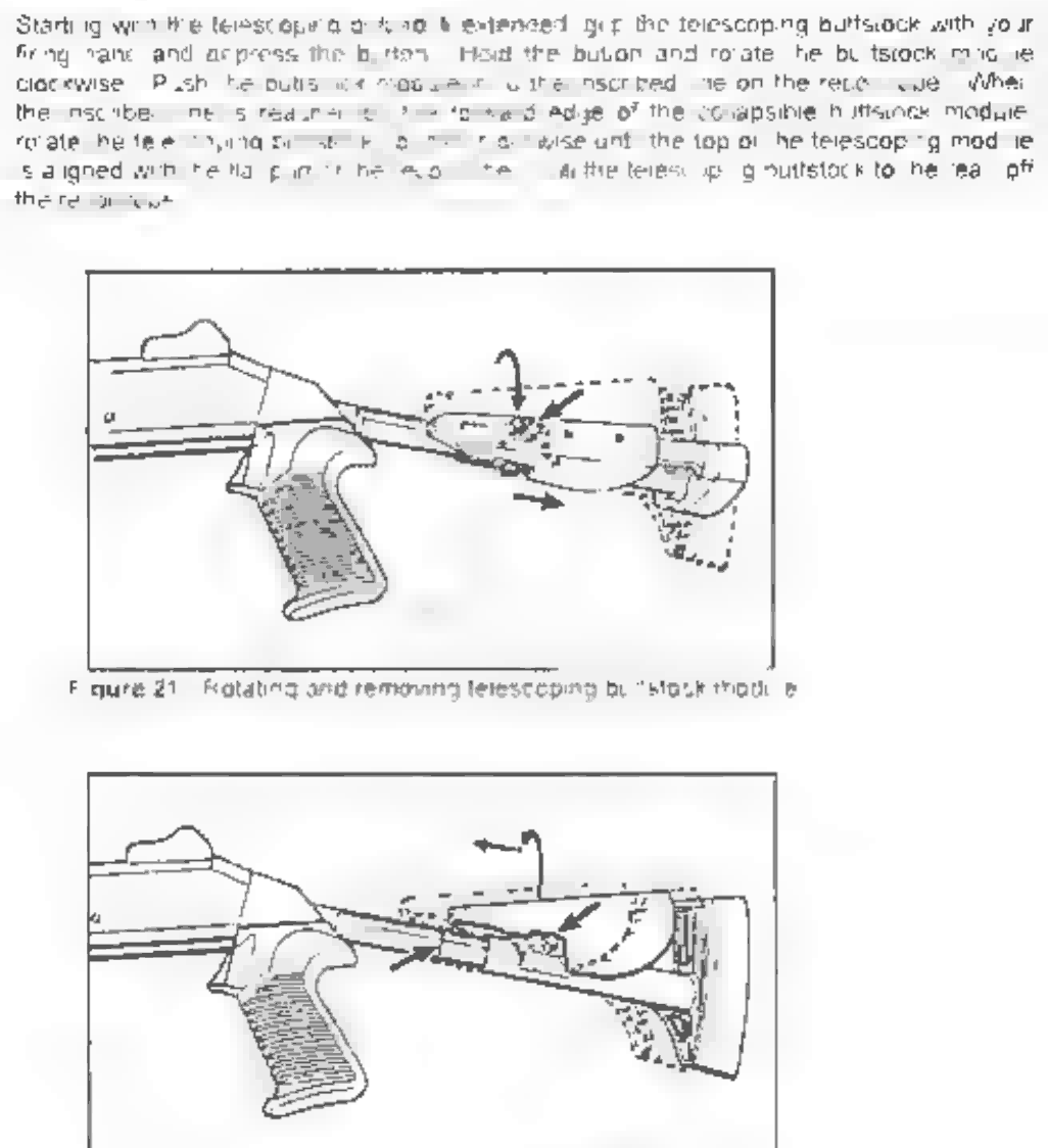
Detail StripWith the trigger group out, extends the telescoping buttstock, rotates and slides the stock module off the recoil spring tube, then unscrews the detachable pistol grip from the receiver (pp. 35-37). Operator level in the USMC operator's manual, which states that only a trained armorer may go beyond this level of disassembly.
Applies to: M1014 / M4 with the telescoping buttstock and detachable pistol grip
Follows TM 10698A-10/1 (preliminary): Preliminary TM 10698A-10/1, U.S. Marine Corps Technical Manual: Operator's Manual for Shotgun, Combat, 12 Gauge, Semi-Automatic, M1014 (1005-01-472-3147) [For Official Use Only] — Headquarters, U.S. Marine Corps (Marine Corps Systems Command), p. Operator disassembly, Extending/Removing archive.org [5]
- Remove the trigger group from the receiver (field strip).TipThe manual's stock removal starts 'With the trigger guard removed'.
- With the buttstock collapsed, grip it with your firing hand and depress the button with your thumb.
- Rotate the telescoping buttstock clockwise and pull it to the rear.
- When the buttstock is fully extended, rotate it counterclockwise to the vertical position and release the button.
- Grip the extended buttstock with your firing hand, depress the button, and keep it fully depressed while you rotate the buttstock module clockwise.TipThe manual's note: keep the button completely depressed while removing the buttstock.
- Push the buttstock module in to the inscribed line on the recoil tube.
- When the forward edge of the buttstock module reaches the inscribed line, rotate the buttstock counterclockwise until the top of the telescoping module lines up with the flat part of the recoil tube.
- Pull the telescoping buttstock to the rear off the recoil tube.Removed at this step:
Telescoping buttstock module - Unscrew the pistol grip counterclockwise until it is free and remove it to the rear over the recoil tube.Removed at this step:
Pistol grip
Disassemble the bolt group
Detail StripRemoves the firing pin retaining pin, firing pin and spring, cam pin and bolt head from the bolt carrier (Assembly groups, Bolt group, p. 38). Operator level in the USMC operator's manual, which states that only a trained armorer may go beyond this level of disassembly. The extractor, link and bolt handle retaining pin stay in place.
Follows TM 10698A-10/1 (preliminary): Preliminary TM 10698A-10/1, U.S. Marine Corps Technical Manual: Operator's Manual for Shotgun, Combat, 12 Gauge, Semi-Automatic, M1014 (1005-01-472-3147) [For Official Use Only] — Headquarters, U.S. Marine Corps (Marine Corps Systems Command), p. Assembly groups, 1. Bolt group, pp. 38-3 archive.org [5]
- Remove the bolt group from the receiver (field strip).WarningDo NOT remove the extractor, link or bolt handle retaining pin during operator disassembly. It is not required to remove these parts for operator cleaning or maintenance.
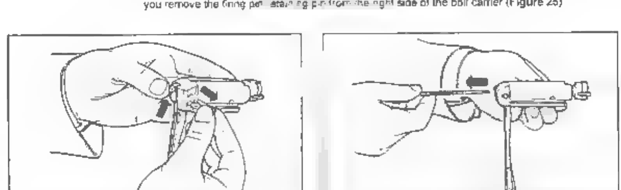
- Place a finger over the rear end of the firing pin and remove the firing pin retaining pin from the right side of the bolt carrier.Removed at this step:
Firing pin retaining pin - Lift the firing pin, with its spring, out of the recess in the rear of the bolt carrier.Removed at this step:
Firing pin with firing pin spring - Separate the firing pin spring from the firing pin.Removed at this step:
Firing pin springFiring pin - Lift or shake the cam pin out of the bolt assembly.Removed at this step:
Cam pin - Pull the bolt head out of the bolt carrier.Removed at this step:
Bolt head
Remove the gas cylinder plugs and gas pistons
Detail StripUnscrews both gas cylinder plugs with the bolt handle and pushes the gas pistons out of the front of the cylinders (Assembly groups, 2. Barrel, p. 39). Needed only for major cleaning (every 5,000 rounds), or when water, debris or heavy fouling stops the pistons moving freely. Operator level in the USMC operator's manual, which states that only a trained armorer may go beyond this level of disassembly.
Follows TM 10698A-10/1 (preliminary): Preliminary TM 10698A-10/1, U.S. Marine Corps Technical Manual: Operator's Manual for Shotgun, Combat, 12 Gauge, Semi-Automatic, M1014 (1005-01-472-3147) [For Official Use Only] — Headquarters, U.S. Marine Corps (Marine Corps Systems Command), p. Assembly groups, 2. Barrel, pp. 39-40 archive.org [5]
- Remove the barrel from the receiver (field strip).TipThe gas system need not be taken apart at every field strip; the manual calls for it every 5,000 rounds or when there is water, debris or excessive fouling in the gas system.
- Using the bolt handle, unscrew the gas cylinder plugs counterclockwise as viewed from the front of the barrel.Removed at this step:
Gas cylinder plugs (2) - Remove the gas pistons from the front end of the gas cylinders.Removed at this step:
Gas pistons (2)
Install the magazine follower, spring and spring seal ring
Detail ReassemblyPuts the follower in red end first, then the spring, then squeezes and rolls the magazine spring seal ring into the tube mouth (operator reassembly step 7, p. 48). Operator level in the USMC operator's manual, which states that only a trained armorer may go beyond this level of disassembly.
Follows TM 10698A-10/1 (preliminary): Preliminary TM 10698A-10/1, U.S. Marine Corps Technical Manual: Operator's Manual for Shotgun, Combat, 12 Gauge, Semi-Automatic, M1014 (1005-01-472-3147) [For Official Use Only] — Headquarters, U.S. Marine Corps (Marine Corps Systems Command), p. Operator reassembly, step 7, p. 48 archive.org [5]
- Insert the magazine follower into the end of the magazine tube with its red, smaller-diameter end with the raised tactile ring going in first.
- Insert the magazine spring into the magazine tube behind the follower.
- Insert the magazine spring seal ring, squeezing it and pressing down from the top while rotating it forward until the seal is set.WarningMake sure the muzzle end of the magazine points in a safe direction while removing the magazine cap and the magazine spring seal ring. The magazine parts are under considerable spring tension and can injure you or bystanders if released. If the magazine spring seal is worn, it may come out when the cap is removed and eject the magazine spring.TipFigure 42 shows the three stages of seating the seal ring.
- Install the barrel and forearm, then screw the magazine cap on hand tight to the last click.TipThe manual's step 8 holds the bolt group at least 1/4 in to the rear with the bolt handle while the barrel extension goes in, and checks that both gas pistons enter their holes in the front of the receiver.
Install the pistol grip and telescoping buttstock
Detail ReassemblyScrews the pistol grip onto the receiver until flush and vertical, then fits the telescoping buttstock to the recoil tube by the reverse rotation sequence (p. 44). The trigger group goes back in afterwards. Operator level in the USMC operator's manual, which states that only a trained armorer may go beyond this level of disassembly.
Applies to: M1014 / M4 with the telescoping buttstock and detachable pistol grip
Follows TM 10698A-10/1 (preliminary): Preliminary TM 10698A-10/1, U.S. Marine Corps Technical Manual: Operator's Manual for Shotgun, Combat, 12 Gauge, Semi-Automatic, M1014 (1005-01-472-3147) [For Official Use Only] — Headquarters, U.S. Marine Corps (Marine Corps Systems Command), p. Operator reassembly, Weapon, Buttstock, archive.org [5]
- Place the pistol grip over the rear end of the recoil spring tube at the back of the receiver.
- Screw the pistol grip onto the receiver clockwise, as viewed from the rear, until it is flush against the back of the receiver and vertical.
- Grip the telescoping buttstock with your firing hand and depress the button.
- Rotate the buttstock counterclockwise until its top lines up with the flat part of the recoil tube.
- Push the buttstock up the recoil tube to the inscribed line.
- Rotate the buttstock clockwise past vertical and push it forward.
- Rotate the buttstock counterclockwise and release the button.
Reassemble the bolt group
Detail ReassemblyFits the bolt head with the extractor to the right, the cam pin with its index line parallel to the carrier, then the firing pin and spring, held in by the retaining pin pushed in from right to left (pp. 41-43). Operator level in the USMC operator's manual, which states that only a trained armorer may go beyond this level of disassembly.
Follows TM 10698A-10/1 (preliminary): Preliminary TM 10698A-10/1, U.S. Marine Corps Technical Manual: Operator's Manual for Shotgun, Combat, 12 Gauge, Semi-Automatic, M1014 (1005-01-472-3147) [For Official Use Only] — Headquarters, U.S. Marine Corps (Marine Corps Systems Command), p. Operator reassembly, 2. Bolt group, pp. archive.org [5]
- Insert the bolt head into the front of the bolt carrier with the extractor to the right.
- Insert the cam pin through the hole in the bolt head so that the hole through the cam pin and the index line on its top run parallel with the bolt carrier.
- Place the firing pin spring onto the front end of the firing pin.
- Insert the firing pin, with its spring, into the hole in the back end of the bolt carrier.
- Press in on the back of the firing pin with your finger against spring tension and push the firing pin retaining pin into the bolt carrier from right to left.WarningDo not try to place the firing pin retaining pin completely behind the end of the firing pin.
- Check that the back end of the firing pin is visible at the back of the bolt carrier and that the firing pin moves freely when pushed in with a pointed object.
Install the gas pistons and gas cylinder plugs
Detail ReassemblyPuts the gas pistons back with the long extension toward the rear of the barrel and tightens the plugs clockwise with the bolt handle (Operator reassembly, 1. Barrel, p. 41). Operator level in the USMC operator's manual, which states that only a trained armorer may go beyond this level of disassembly.
Follows TM 10698A-10/1 (preliminary): Preliminary TM 10698A-10/1, U.S. Marine Corps Technical Manual: Operator's Manual for Shotgun, Combat, 12 Gauge, Semi-Automatic, M1014 (1005-01-472-3147) [For Official Use Only] — Headquarters, U.S. Marine Corps (Marine Corps Systems Command), p. Operator reassembly, 1. Barrel, p. 41 archive.org [5]
- Install the gas pistons in the gas cylinders with the long extension facing the rear of the barrel.
- Install the gas cylinder plugs and tighten them clockwise, as viewed from the front of the barrel, using the bolt handle.
Reassembly
Reassembly- Install the trigger group into the receiver and insert its pin fully.
- Slide the bolt assembly into the receiver, engaging the link with the recoil spring plunger.
- Install the bolt handle into the bolt.
- Reinstall the two gas pistons into their cylinders in the correct orientation.WarningReversed pistons will not seal and the shotgun will not cycle correctly.
- Set the barrel into the receiver with its extension seated fully and its ring over the magazine tube.
- Install the forend and thread the magazine cap on, hand-tightening firmly.WarningA loose magazine cap causes malfunctions and lets the barrel move. Check it before every use.
- Cycle the action several times and perform the function check.
Diagrams
public domainThese are reproduced from government technical manuals, which are not subject to copyright. Manufacturer manual diagrams are not reproduced here — the entry links to the manual instead.
Torque specifications
No sourced torque values from the manufacturer are recorded for this firearm. Where a fastener has a specified torque — action screws, scope bases, muzzle devices, barrel nuts — get it from the manufacturer or a gunsmith rather than estimating it.
What the manufacturer does say: The manufacturer's documents give no torque value. They say: "Screw on the fore-end fastening cap, on the end of the tubular magazine and tighten firmly until the barrel and the fore grip are locked perfectly against the receiver (fig. 10)." (M4 Tactical Shotgun Product Manual, PDF p. 49)
Reported by other sources — not the manufacturer
| Fastener | Torque | Who says so, and their words | Where it comes from |
|---|---|---|---|
| Handguard mounting bolts (6: four on forward ring, two on rear retaining cap) Midwest Industries Benelli M4 M-LOK Handguard (MI-BENM4-HG) on a Benelli M4 (and clones) |
20 in-lb 2.3 N·m · 1.7 ft-lb |
Reported by Midwest Industries, Inc. Start screws finger tight; tighten barrel assembly fully seated; then torque all 6; then brass set screws only until they touch. “Tighten all 6 mounting bolts to 20inch lbs.” |
Midwest Industries Benelli M4 Handguard (MI-BENM4-HG) — Instructions — Midwest Industries, Inc., PDF p. 1 (single page) midwestindustriesinc.com [6] |
| Reflex sight mount to receiver (three screws and washers, factory rail holes) Mesa Tactical RMR-footprint reflex sight mount on a Benelli M4 |
approx. 15 in-lb 1.7 N·m · 1.2 ft-lb |
Reported by Mesa Tactical Threadlocker: Purple or blue thread locker recommended “For Benelli M2 Tactical and Benelli M4 use the three screws and washers. For Beretta 1301 Tactical use the two metric flathead screws. Tighten to about 15 inch-lbs.” |
Mesa Tactical Reflex Sight Mounts Manual (46020 rev e) — Mesa Tactical, PDF p. 4 of 8 mesatactical.com [7] |
| ACRO sight mount to receiver (#8-40 x 1/4" flathead screws, three) Mesa Tactical ACRO-footprint reflex sight mount on a Benelli M4 |
approx. 15 in-lb 1.7 N·m · 1.2 ft-lb |
Reported by Mesa Tactical Threadlocker: Purple or blue thread locker recommended “Use three screws and included hex key to tighten the sight mount to the receiver. Tighten to about 15 inch-lbs.” |
Mesa Tactical Reflex Sight Mounts Manual (46020 rev e) — Mesa Tactical, PDF p. 6 of 8 mesatactical.com [7] |
| SureShell carrier/ACRO mount to receiver (four #8-40 screws) Mesa Tactical SureShell carrier with ACRO sight mount on a Benelli M4 |
approx. 15 in-lb 1.7 N·m · 1.2 ft-lb |
Reported by Mesa Tactical Threadlocker: Purple or blue thread lock recommended “Use the four screws and hex key included in your zip bag hardware kit. Tighten screws to about 15 inch-lbs.” |
Mesa Tactical SureShell Carrier and ACRO Sight Mount Manual (46028) — Mesa Tactical, PDF p. 5 of 9 mesatactical.com [8] |
| Integrated-rail SureShell carrier to receiver (four or five screws and washers, factory rail holes) Mesa Tactical Integrated Rail SureShell shotshell carrier on a Benelli M4/M1014 |
approx. 15 in-lb 1.7 N·m · 1.2 ft-lb |
Reported by Mesa Tactical Threadlocker: Blue Loctite on each screw “the four or five screws and washers (the SureShell carriers for the Benelli SuperNova Tactical do not include washers). Tighten to about 15 inch-lbs and use a drop of blue Loctite® on each screw.” |
Mesa Tactical SureShell Shotshell Carriers — Assembly and Operation Guide (47374) — Mesa Tactical, PDF p. 16 of 20 mesatactical.com [9] |
Materials and factory finish
As stated by Benelli Armi. Prep, masking and cure depend on these; a polymer or aluminium part, a nitrided or anodised finish, and a blued steel part are each a different job. Variants with other finishes may exist — check the maker's page for the exact SKU on the bench.
| Component | Material | Factory finish | Where it comes from |
|---|---|---|---|
| Receiver M4 Black | Ergal | mat black anodised | Benelli M4 Black — technical data — Benelli Armi S.p.A. benelli.it [4] “RECEIVER FINISHING Ergal, mat black anodised, anti-glare” |
| Stock M4 Black | Technopolymer | — | Benelli M4 Black — technical data — Benelli Armi S.p.A. benelli.it [4] “STOCK AND FORE-END Technopolymer” |
| Barrel M4 Black | — | phosphated | Benelli M4 Black — technical data — Benelli Armi S.p.A. benelli.it [4] “The barrel is chromed inside and phosphated outside.” |
Function check
- Verify the shotgun is unloaded — chamber and magazine tube — before each step.
- Cycle the action by hand and confirm the bolt locks fully into battery.
- With the hammer cocked, engage the safety and press the trigger. The hammer must not fall.
- Disengage the safety and press the trigger. The hammer should fall.
- Confirm the bolt locks open when retracted and releases with the carrier release.
- Load two dummy shells into the magazine and confirm they feed and eject one at a time.
- Confirm the magazine cap is tight.
Maintenance
Lubrication points
- Bolt body and locking lug
- Magazine tube exterior
- Action bars or link
- Hammer and sear pivots
Cleaning notes
Gas-operated shotguns foul their gas system quickly. Clean the gas ports in the barrel, the piston, the piston seals, and the magazine tube every few hundred rounds. Do not oil the gas piston area heavily — oil there mixes with carbon into a paste that stops the gun.
Suggested inspection interval: roughly every 500 rounds. This is a general guideline, not a manufacturer specification.
Wear parts to inspect
Gas piston and seals · Barrel seal O-ring where fitted · Action spring · Extractor · Link
Common issues
| Symptom | Likely cause | What to do |
|---|---|---|
| Short-stroking or failure to lock back | Carbon buildup in the gas cylinders and on the pistons | Clean the gas pistons and cylinders thoroughly. This is the standard M4 maintenance item. |
| Shotgun will not cycle after cleaning | Gas pistons installed reversed | Check piston orientation against a parts diagram. |
| Malfunctions that come and go | Loose magazine cap | Hand-tighten firmly and check before use. |
Also covers
The procedures above are reported to apply to: Benelli M1014 · Benelli M4 Tactical and H2O variants. Verify against the manual for your specific model.
Similar manual of arms
Legal notes
Sourcing
- Confidence
- medium — Drawn from reliable secondary sources and consistent across references, but not confirmed against a primary source.
- Verification
- Community reviewed only
- Last updated
- 2026-10-29
References
Every source this page draws on, with its web address so you can read it yourself. Numbers in brackets elsewhere on the page point here.
- [1] Benelli M4 Use and Maintenance Manual — Benelli Armi S.p.A. manufacturer manual primary source
- [2] TM 10698A-10/1 (preliminary): Operator's Manual, Shotgun, Combat, 12 Gauge, Semi-Automatic, M1014 — U.S. Marine Corps military technical manual primary source
- [3] M4 Tactical Shotgun Product Manual — Benelli USA / Benelli Armi S.p.A. manufacturer manual primary source
https://www.benelliusa.com/sites/default/files/content/media/manuals/2019-10/M4%20Tactical%20Shotgun%20Product%20Manual.pdf (checked 2026-09-27) - [4] Benelli M4 Black — technical data — Benelli Armi S.p.A. website primary source
https://www.benelli.it/en/arma/m4-black (checked 2026-10-03) - [5] TM 10698A-10/1 (preliminary): Preliminary TM 10698A-10/1, U.S. Marine Corps Technical Manual: Operator's Manual for Shotgun, Combat, 12 Gauge, Semi-Automatic, M1014 (1005-01-472-3147) [For Official Use Only] — Headquarters, U.S. Marine Corps (Marine Corps Systems Command) (2000) military technical manual primary source
https://archive.org/download/benelli-m-4-usmc-manual/Benelli%20M4%20%28USMC%20Manual%29_text.pdf (checked 2026-10-03) - [6] Midwest Industries Benelli M4 Handguard (MI-BENM4-HG) — Instructions — Midwest Industries, Inc. manufacturer manual secondary source
https://midwestindustriesinc.com/content/installation-instructions/Benelli-M4-Handguard-MI-BENM4-HG-Instructions.pdf (checked 2026-10-11) - [7] Mesa Tactical Reflex Sight Mounts Manual (46020 rev e) — Mesa Tactical manufacturer manual secondary source
https://mesatactical.com/content/manuals/46020_Reflex_Sight_Mounts_Manual_rev_e.pdf (checked 2026-10-11) - [8] Mesa Tactical SureShell Carrier and ACRO Sight Mount Manual (46028) — Mesa Tactical manufacturer manual secondary source
https://mesatactical.com/content/manuals/46028_SureShell_Carrier_and_ACRO_Sight_Mount_Manual.pdf (checked 2026-10-11) - [9] Mesa Tactical SureShell Shotshell Carriers — Assembly and Operation Guide (47374) — Mesa Tactical manufacturer manual secondary source
https://mesatactical.com/content/manuals/47374_SureShell_Shotshell_Carriers_Assembly_and_Operation_Guide.pdf (checked 2026-10-11)
Notes: The M4 is the gas-operated outlier in a line otherwise built on the inertia system. That distinction drives its entire maintenance profile and is the thing most likely to catch out someone who owns other Benellis.