← All firearms · Printable work order
Browning Auto-5
- advanced
- Shop tier 3
- medium confidence
- Shotgun
- long recoil
- historic
- john browning
- friction ring
- semi auto shotgun
field strip ~6 min · reassembly ~10 min · detail strip ~40 min
Specifications
- Manufacturer
- Browning Arms Company
- Origin
- Belgium / Japan
- Category
- Shotgun
- Action
- Recoil-operated
- Calibers
- 12 gauge, 16 gauge, 20 gauge
- Capacity
- 4+1 typical
- Production
- 1902–1998 (discontinued)
- Also known as
- A-5, Humpback, Remington Model 11 (licensed)
Model-specific safety
- The Auto-5 is a LONG RECOIL action: the barrel and bolt travel all the way rearward together, then the barrel returns forward while the bolt stays back. Nothing else in common circulation works this way, and the barrel moving under recoil is normal, not a fault.
- The friction ring and friction piece on the magazine tube MUST be set correctly for the load you are firing — one arrangement for light loads, a different one for heavy loads. Setting them wrong either batters the gun severely or stops it cycling. This is the single most important thing to know about an Auto-5, and it is the thing most commonly got wrong.
- Do not fire the gun with the friction rings omitted or assembled arbitrarily. The manual shows the arrangements; follow them.
- The recoil spring in the buttstock is under substantial compression and requires a specific tool to service. It is not part of routine maintenance.
- Unloading a tube magazine takes several cycles. Verify both the chamber and the tube.
Under spring tension
- Recoil spring in the buttstock
- Barrel return spring on the magazine tube
- Magazine tube spring
Easily lost parts
Friction ring · Friction piece · Barrel return spring · Magazine cap
Tools
No tools required for the field strip.
Shop difficulty
Shop tier 3 Tier 3 — hardest among shotguns, for the full job: strip to the parts that get coated and put it back together working. About 91 key-numbered parts, a long-recoil action with a link-and-carrier relationship that must be mated as the bolt goes in, the locking-block latch and action-spring plug each held against spring force while a pin is driven, and a trigger plate full of small detents (safety ball, safety sear plunger) that fly.
Parts: 91 numbered parts (Complete shotgun (Japanese-made Auto-5 Light/Magnum/Sweet 16 list), key numbers 01-91; this page's 173 rows repeat many keys once per gauge variant), from Owner's Manual, Auto-5 Semi-Automatic Shotgun Light 12 and 20 Gauge — Browning, p. 11 archive.org [3].
Bench time: about 90 min to strip, 135 min to rebuild (estimate). Full strip: friction rings and recoil spring, stock and action spring tube, trigger plate (safety sear, safety ball, trigger spring), carrier with locked screws, breech bolt, locking block and link, magazine cutoff and spring retainer. Rebuild longest in the category: held-spring pins (latch, action spring plug), side-specific carrier screws, safety ball and friction ring order.
Small parts: 14 pins, 23 springs, 1 detents or plungers (counted from the manufacturer's parts list (one per key number unless a quantity is given))
What comes off for coating
- Barrel / magazine: magazine cap, fore-end, barrel with extension, recoil spring, friction piece and friction ring, magazine spring retainer and spring — Menck corkscrew magazine-spring tool
- Stock / action spring: tang screw lock screw and tang screw, buttstock, action spring tube cross pin, plug, action spring and follower
- Receiver: trigger plate pin lock screw, trigger plate pin and screw, trigger plate group, carrier spring (older guns, on a stud), carrier screw lock screws and carrier screws (side-specific), carrier, locking block latch pin, latch and spring, breech bolt with link, operating slide / bolt handle, magazine cutoff and spring (bare-receiver jobs), carrier latch button and lever
- Trigger plate: safety sear, follower and spring, hammer pin and hammer, mainspring screw and mainspring, trigger spring crosspin, trigger spring and safety ball, trigger and safety
- Breech bolt: firing pin stop pin, firing pin and spring, locking block and link (link pin staked; leave), extractors and springs
Special tools
- Menck corkscrew magazine-spring tool — Controlling the long magazine spring as the retainer comes out
- 3/32 in. and 1/8 in. punches — Action spring cross pin, latch pin, firing pin stop pin and hammer pin
- 0.060 in. punch — Trigger spring crosspin on newer trigger plates
- Leather strap and grips — Seized magazine cap
- Rubber-faced dead-blow mallet — Stubborn buttstock
Known pain points
- The locking-block latch sits on a spring under the bolt; on reassembly it has to be pressed down against that spring while the latch pin is pushed through receiver, latch and bolt, and on disassembly it pops out when the drift is withdrawn. (both)
Source: TM 9-285 War Department Technical Manual: Shotguns, All Types — Section VIII, Remington Shotgun, 12-Gage, M11 and Sportsman — War Department archive.org [4] — “withdraw pin drift slowly at same time holding down locking block latch against force of latch spring. When drift is removed, ease latch upward and remove latch and spring.” - The action spring plug, spring and follower in the buttstock tube are under compression and must be held against the spring while the cross pin is driven out or in. (both)
Source: How To Disassemble The Browning Auto-5 — Gun Tests gun-tests.com [5] — “Pushing the pin with one hand, hold some tension on the action-spring plug with your other hand so the plug, spring and follower don't go flying out a window.” - The carrier is held by left and right carrier screws with lock screws; the screws are side-specific and the lock screws will not line up if they are swapped, and the carrier spring can fly off its stud. (reassembly)
Source: How To Disassemble The Browning Auto-5 — Gun Tests gun-tests.com [5] — “These carrier screws should be identified as to which side they came out of. If they are switched at reassembly, the lock screws will probably not line up properly.” - Stripping the trigger plate frees a safety-sear follower and spring that shoot out of their hole and a loose safety ball under the trigger spring; the trigger spring must be held depressed while the crosspin goes in. (both)
Source: How To Disassemble The Browning Auto-5 — Gun Tests gun-tests.com [5] — “When removing the trigger spring, the safety ball can easily be lost, so watch for the little ball to try and get away from you.” - Rebuilding the trigger plate means holding the in-battery safety's spring-loaded detent down with a finger while the safety drops in, with a loose ball detent under the trigger that falls out if the plate is tipped. (reassembly)
Owners report: How to Reassemble a Browning A5 (gunsmithing blog) — McCluskey Arms okra-pineapple-bmtb.squarespace.com [6] — “Put the spring and detent into the hole next to the trigger. Hold the detent down with one finger and slide the in-battery safety down into place.”
Fit or check on rebuild
- Friction ring set-up for the customer's loads — Rings set for light loads with heavy ammunition batter the gun and crack the stock; the owner needs the correct arrangement.
Source: How To Disassemble The Browning Auto-5 — Gun Tests gun-tests.com [5] — “If the owner doesn't have a copy of the proper settings of the friction rings for the loads being used, get him a copy of one.” - Carrier screws on their original sides — Swapped screws leave the lock screws misaligned.
Source: How To Disassemble The Browning Auto-5 — Gun Tests gun-tests.com [5] — “If they are switched at reassembly, the lock screws will probably not line up properly.” - Safety detent feel (trigger spring centre leg) — The trigger spring's centre leg sets safety tension and may need bending up or down after reassembly.
Source: How To Disassemble The Browning Auto-5 — Gun Tests gun-tests.com [5] — “If it moves too freely, the center leg on the trigger spring will need to be bent downward to increase the pressure on the safety ball.” - Function check: safety, trigger/sear release, disconnector and feeding with dummy rounds — Standard after any detail strip; a mis-assembled sear or disconnector can double or fail to fire.
This is Pew-Takedown's rating, not the manufacturer's. How tiers are rated. Forum reports are owners' experience, not specifications.
Procedures
Clear and Make Safe
Clear & Make Safe- Point the muzzle in a safe direction and keep your finger off the trigger.
- Engage the safety.
- Pull the bolt handle rearward to eject any chambered shell and lock the bolt open.Removed at this step:
Chambered shell, if present - Cycle the action repeatedly, catching each shell as it ejects, until no more shells feed from the magazine tube.
- With the action open, inspect the chamber and look up the magazine tube with a light.WarningThe chamber AND the tube. A shell hung up in the tube is easy to miss.
- Physically confirm the chamber is empty and remove all live ammunition from the work area.
Field Strip
Field StripThe friction ring arrangement is the part to get right.
- Complete the Clear and Make Safe procedure.
- Unscrew the magazine cap from the end of the magazine tube.Removed at this step:
Magazine cap - Withdraw the forend forward off the magazine tube.Removed at this step:
Forend - Note the exact arrangement and orientation of the friction ring, friction piece, and barrel return spring on the magazine tube before removing them.WarningPhotograph or sketch the arrangement. Getting it back wrong is how Auto-5s get damaged.Removed at this step:
Friction ringFriction pieceBarrel return spring - Pull the barrel forward off the magazine tube and out of the receiver.Removed at this step:
Barrel - Pull the bolt handle out and withdraw the bolt assembly from the receiver.Removed at this step:
Bolt handleBolt assembly - Stop here. The recoil spring in the buttstock requires a dedicated tool.WarningDo not attempt buttstock recoil spring service without the correct tool.
Remove the butt stock and trigger plate group
Detail Strip tools required gunsmith recommendedFirst step of taking the receiver groups out: the stock comes off the action spring tube, then the trigger plate group is unpinned and unscrewed. TM 9-285 assigns this to the using arm (troop level): par. 1c says disassembly and assembly 'will be undertaken only under the supervision of an officer or the chief mechanic', and the field-inspection paragraph limits using troops to the removal and replacement of groups described here. Anything further (adjustment, stoning, trigger work, headspace) goes to ordnance personnel. Source gun is the Remington Model 11 (licensed Browning Auto-5). TM 9-285
Applies to: Remington Model 11 (licensed Auto-5); check against the Browning
Follows TM 9-285 War Department Technical Manual: Shotguns, All Types — Section VIII, Remington Shotgun, 12-Gage, M11 and Sportsman — War Department, par. 56 a (2)-(3), p. 183 archive.org [4]
- Remove the barrel and fore end, then hold the operating handle, press the carrier latch button and ease the breech bolt forward.WarningDo not press the carrier latch button and let the breech bolt spring forward after the barrel is removed; ease it forward against the action spring.
- Remove the tang screw locking screw.Removed at this step:
Tang screw locking screw - Remove the tang screw from the underside of the trigger plate tang (the rear screw in the tang).Removed at this step:
Tang screw - Pull the butt stock to the rear off the receiver and the action spring tube.TipIf the stock is hard to withdraw, remove the trigger plate pin, press the carrier latch button to release the carrier, and press the forward end of the trigger plate upward slightly into the receiver.Removed at this step:
Butt stock - Remove the trigger plate pin locking screw from the lower left side of the receiver, near the center.Removed at this step:
Trigger plate pin locking screw - With a pin drift, drive the trigger plate pin out from right to left.Removed at this step:
Trigger plate pin - Remove the trigger plate screw from the lower rear corner of the left side of the receiver.Removed at this step:
Trigger plate screw - Pull the trigger plate group downward out of the receiver.Removed at this step:
Trigger plate group
Remove the carrier
Detail Strip tools required gunsmith recommendedThe carrier spring is unhooked and the carrier is lifted out after its two pivot screws are removed. TM 9-285 assigns this to the using arm (troop level): par. 1c says disassembly and assembly 'will be undertaken only under the supervision of an officer or the chief mechanic', and the field-inspection paragraph limits using troops to the removal and replacement of groups described here. Anything further (adjustment, stoning, trigger work, headspace) goes to ordnance personnel. Source gun is the Remington Model 11 (licensed Browning Auto-5). TM 9-285 allows this to using troops only under the s
Applies to: Remington Model 11 (licensed Auto-5); check against the Browning
Follows TM 9-285 War Department Technical Manual: Shotguns, All Types — Section VIII, Remington Shotgun, 12-Gage, M11 and Sportsman — War Department, par. 56 a (4), p. 183 archive.org [4]
- Press the forward end of the carrier spring from under its retaining stud and remove the spring from its pivot stud.WarningBe careful the spring does not fly out when you disengage its forward end.Removed at this step:
Carrier spring - Remove the carrier screw locking screws from the right and left sides of the receiver.Removed at this step:
Carrier screw locking screws (2) - Remove the carrier screws, the largest screws in the sides of the receiver just to the rear of center.Removed at this step:
Carrier screws (2) - Lift out the carrier.Removed at this step:
Carrier
Remove the action spring from the action spring tube
Detail Strip tools required gunsmith recommendedWith stock, trigger plate and carrier out, the action (recoil) spring in the tube behind the receiver is released by drifting out the cross pin through its wooden plug. The manual does this with a pin drift and finger pressure. TM 9-285 assigns this to the using arm (troop level): par. 1c says disassembly and assembly 'will be undertaken only under the supervision of an officer or the chief mechanic', and the field-inspection paragraph limits using troops to the removal and replacement of groups described here. Anything further (adjustment, stoning, trigger work, headspace) goes to ordnance pe
Applies to: Remington Model 11 (licensed Auto-5); check against the Browning
Follows TM 9-285 War Department Technical Manual: Shotguns, All Types — Section VIII, Remington Shotgun, 12-Gage, M11 and Sportsman — War Department, par. 56 a (5), p. 183 archive.org [4]
- Press in the wooden plug at the rear end of the action spring tube.
- With a pin drift, push out the cross pin.Removed at this step:
Plug cross pin - Holding the plug with a finger against the force of the spring, withdraw the drift slowly and ease the plug and spring to the rear out of the tube.WarningThe spring is under compression; let it out slowly.
- When the spring is fully expanded, pull the plug, spring and spring follower to the rear out of the tube.Removed at this step:
Action spring plugAction springAction spring follower
Remove the breech bolt and link
Detail Strip tools required gunsmith recommendedThe locking block latch pin is drifted out through a hole in the left receiver wall, then the bolt and link go out the front of the receiver while the operating slide drops free. TM 9-285 assigns this to the using arm (troop level): par. 1c says disassembly and assembly 'will be undertaken only under the supervision of an officer or the chief mechanic', and the field-inspection paragraph limits using troops to the removal and replacement of groups described here. Anything further (adjustment, stoning, trigger work, headspace) goes to ordnance personnel. Source gun is the Remington Model 11 (li
Applies to: Remington Model 11 (licensed Auto-5); check against the Browning
Follows TM 9-285 War Department Technical Manual: Shotguns, All Types — Section VIII, Remington Shotgun, 12-Gage, M11 and Sportsman — War Department, par. 56 a (6), pp. 183-184 archive.org [4]
- Move the recoil spring, friction piece and friction ring forward on the magazine tube.
- Move the breech bolt until the locking block latch pin lines up with the hole in the left side of the receiver to the rear of the shell stop.
- With a straight pin drift, push the pin clear through the breech bolt and receiver from right to left.Removed at this step:
Locking block latch pin - Withdraw the drift slowly while holding the locking block latch down against the force of its spring.
- When the drift is out, ease the latch upward and remove the latch and its spring.Removed at this step:
Locking block latchLocking block latch spring - Swing the rear end of the link downward to clear the operating slide.
- Move the breech bolt forward out of the receiver with the link attached; the operating slide slides out of the bolt as its handle strikes the forward edge of the ejection opening.Removed at this step:
Breech bolt with linkOperating slide
Replace the breech bolt and link
Detail Reassembly tools required gunsmith recommendedBolt and link go in from the front, the operating slide is fed in through the ejection opening, then the locking block latch is pinned. TM 9-285 assigns this to the using arm (troop level): par. 1c says disassembly and assembly 'will be undertaken only under the supervision of an officer or the chief mechanic', and the field-inspection paragraph limits using troops to the removal and replacement of groups described here. Anything further (adjustment, stoning, trigger work, headspace) goes to ordnance personnel. Source gun is the Remington Model 11 (licensed Browning Auto-5). TM 9-285 allows th
Applies to: Remington Model 11 (licensed Auto-5); check against the Browning
Follows TM 9-285 War Department Technical Manual: Shotguns, All Types — Section VIII, Remington Shotgun, 12-Gage, M11 and Sportsman — War Department, par. 57 a (1), p. 184 archive.org [4]
- Clean, lightly oil and lubricate the parts before replacing them.
- With the recoil spring, friction piece and ring moved forward on the magazine tube, slide the link and breech bolt, link first, into the forward end of the receiver so the guides on the lower face of the bolt mate with the guideways in the receiver.
- Move the bolt rearward until half of it has entered the receiver.
- Holding the operating slide by its handle, slip its rear end into the receiver behind the bolt through the ejection opening.
- Hold the slide parallel to the bolt and move the bolt rearward, mating the guides on the slide with the guideways in the right side of the bolt, until the slide is seated in the bolt.TipThe link must point downward for the slide to mate.
- Slide the recoil spring, friction piece and friction ring rearward on the magazine tube in their proper order and position, and replace the fore end to hold them.
- Slide the breech bolt rearward until the locking block latch pin holes in bolt and receiver line up, and insert the latch pin through the left side of the receiver and the left wall of the bolt to hold it.
- Replace the latch spring in its seat in the bolt and place the latch on top of it, long flat end to the rear and drilled lug down.
- Press the latch down on its spring, line up its hole with those in receiver and bolt, and push the pin through latch and bolt until it is flush with both sides of the bolt.
- Move the bolt to check that the pin does not interfere with the receiver.
Replace the carrier
Detail Reassembly tools required gunsmith recommendedCarrier goes in dog up and to the rear under the spring retaining stud; the carrier spring is hooked back under the stud last. TM 9-285 assigns this to the using arm (troop level): par. 1c says disassembly and assembly 'will be undertaken only under the supervision of an officer or the chief mechanic', and the field-inspection paragraph limits using troops to the removal and replacement of groups described here. Anything further (adjustment, stoning, trigger work, headspace) goes to ordnance personnel. Source gun is the Remington Model 11 (licensed Browning Auto-5). TM 9-285 allows this to usi
Applies to: Remington Model 11 (licensed Auto-5); check against the Browning
Follows TM 9-285 War Department Technical Manual: Shotguns, All Types — Section VIII, Remington Shotgun, 12-Gage, M11 and Sportsman — War Department, par. 57 a (2), pp. 184-185 archive.org [4]
- With the receiver bottom side up, move the breech bolt forward and push the link toward the top of the receiver.
- With the carrier dog up and to the rear, slide the carrier beneath the spring retaining stud into the receiver and line up its screw holes with those in the receiver.
- Replace the carrier screws, catching the threads of both before tightening either.WarningBe careful not to cross-thread them.
- Turn the screws until the cuts in their heads line up with the countersinks for the locking screws, and replace the locking screws.
- Slide the carrier spring onto the pivot stud in the left rear of the receiver so that its short leaf rests on the rear of the carrier.
- Press down the long leaf of the spring and slip it under the retaining stud head just forward of the pivot stud, holding the spring so it does not slip off the pivot stud.
Replace the action spring
Detail Reassembly tools required gunsmith recommendedThe follower must seat on the rear nose of the link before the plug is pinned. TM 9-285 assigns this to the using arm (troop level): par. 1c says disassembly and assembly 'will be undertaken only under the supervision of an officer or the chief mechanic', and the field-inspection paragraph limits using troops to the removal and replacement of groups described here. Anything further (adjustment, stoning, trigger work, headspace) goes to ordnance personnel. Source gun is the Remington Model 11 (licensed Browning Auto-5). TM 9-285 allows this to using troops only under the supervision of an offic
Applies to: Remington Model 11 (licensed Auto-5); check against the Browning
Follows TM 9-285 War Department Technical Manual: Shotguns, All Types — Section VIII, Remington Shotgun, 12-Gage, M11 and Sportsman — War Department, par. 57 a (3), p. 185 archive.org [4]
- With the breech bolt forward, insert the action spring, follower first, into the rear end of the action spring tube.
- Push it through the tube and mate the rear nose of the link with the indent in the follower.
- Press the spring into the tube until the head of the wooden plug is flush with the end of the tube.
- Turn the plug until its pin hole lines up with the hole in the tube and insert the plug pin.TipA pin drift may be used to hold the plug while inserting the pin.
- Still holding the plug, push the pin through until it is flush with the tube.
Replace the trigger plate group and butt stock
Detail Reassembly tools required gunsmith recommendedTrigger plate goes in with bolt forward and hammer cocked; pin, locking screw and screw, then the stock and tang screw. TM 9-285 assigns this to the using arm (troop level): par. 1c says disassembly and assembly 'will be undertaken only under the supervision of an officer or the chief mechanic', and the field-inspection paragraph limits using troops to the removal and replacement of groups described here. Anything further (adjustment, stoning, trigger work, headspace) goes to ordnance personnel. Source gun is the Remington Model 11 (licensed Browning Auto-5). TM 9-285 allows this to using troo
Applies to: Remington Model 11 (licensed Auto-5); check against the Browning
Follows TM 9-285 War Department Technical Manual: Shotguns, All Types — Section VIII, Remington Shotgun, 12-Gage, M11 and Sportsman — War Department, par. 57 a (4)-(5), p. 185 archive.org [4]
- With the breech bolt forward and the hammer cocked, press the trigger plate group, tang to the rear, horizontally upward into the rear underside of the receiver and adjust it until the pin and screw holes in plate and receiver line up.TipIf the plate does not seat easily, retract the operating slide slightly to let the safety sear enter the slot in the link.
- Insert the trigger plate pin from the left side and push it through until its head is flush with the face of the receiver.
- With a screwdriver in the slotted head of the pin, turn the pin until the cut in its head lines up with the locking screw countersink in the receiver, then replace the locking screw.
- Insert the trigger plate screw from the left side of the receiver, catch the threads and turn it down tightly.
- Push the butt stock on over the action spring tube until it fits snugly and evenly against the rear face of the receiver and the tang screw holes in trigger plate tang and stock line up.WarningDo not strike the butt on a hard surface.TipThe stock may be seated by striking the butt smartly with the heel of the hand.
- Replace the tang screw and screw it in tightly until the cut in its head lines up with the locking screw countersink in the tang, then replace the locking screw.TipIf the stock is hard to replace, remove the trigger plate pin and put it back after the stock is on.
Reassembly
Reassembly- Insert the bolt assembly into the receiver and install the bolt handle.
- Set the barrel into the receiver with its extension seated.
- Install the barrel return spring, friction piece, and friction ring on the magazine tube in the arrangement correct for the loads you will fire.WarningLight loads and heavy loads use different arrangements. Consult the manual — this is not a detail to guess at.
- Install the forend.
- Thread the magazine cap on and hand-tighten firmly.
- Cycle the action several times and perform the function check.
Diagrams
public domainThese are reproduced from government technical manuals, which are not subject to copyright. Manufacturer manual diagrams are not reproduced here — the entry links to the manual instead.
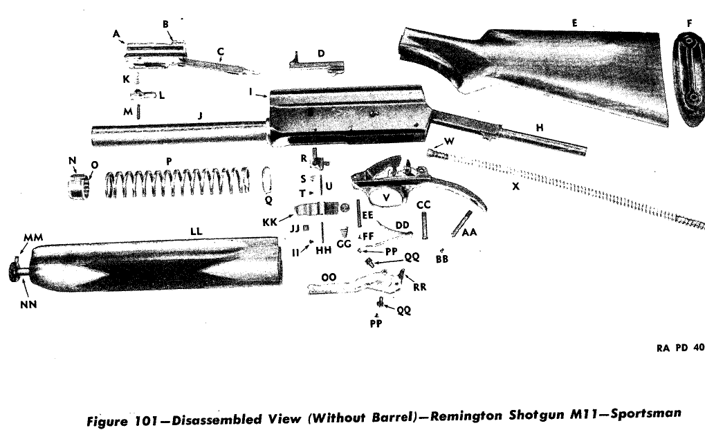
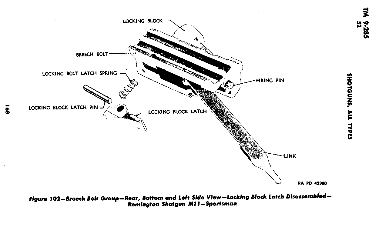
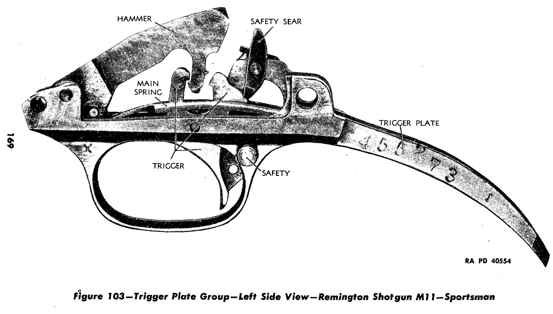
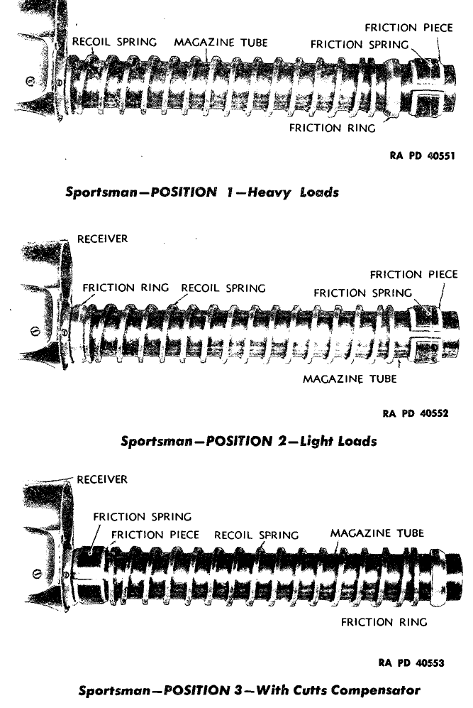
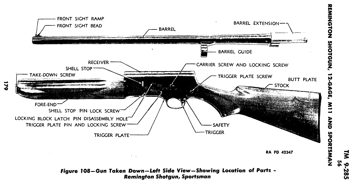
Torque specifications
No sourced torque values from the manufacturer are recorded for this firearm. Where a fastener has a specified torque — action screws, scope bases, muzzle devices, barrel nuts — get it from the manufacturer or a gunsmith rather than estimating it.
What the manufacturer does say: The manufacturer's documents give no torque value. They say: "BE CERTAIN THE MAGAZINE CAP IS SCREWED COMPLETELY DOWN FORCING THE REAR END OF THE FOREARM INTO FIRM CONTACT WITH THE FRONT END OF THE RECEIVER." (Browning Auto-5 Magnum Owner's Manual (web))
Parts list
Transcribed from the manufacturer's parts list (Owner's Manual, Auto-5 Semi-Automatic Shotgun Light 12 and 20 Gauge — Browning, p. 11 archive.org [3]) — "Parts List: Auto-5 Semi-Automatic Shotgun 12, 16 and 20 Gauge" (Japanese-made Auto-5 Light/Magnum/Sweet 16 era), one row per gauge variant. The Magnum manual prints the same list renumbered, titled Magnum 12 and 20; not duplicated. Some part numbers were read from a low-resolution scan; confirm the. Key numbers refer to the exploded view in that document.
173 parts
| Key | Part | Part no. | Qty | Group |
|---|---|---|---|---|
| 01 | Action Spring All Gauges | P011001 | 1 | |
| 02 | Action Spring Follower All Gauges | P011003 | 1 | |
| 03 | Action Spring Plug All Gauges | P011005 | 1 | |
| 04 | Action Spring Plug Pin All Gauges | P011007 | 1 | |
| 05 | Action Spring Tube All Gauges | P011009 | 1 | |
| 06 | Barrel Extension Assembly, Magnum 12 Gauge *Indicates part must be fitted by Browning Service Department or qualified gunsmith. | P011015 | 1 | |
| Barrel Extension Assembly, 12 Printed under key 06, which an earlier row already uses; key omitted here to keep keys unique. *Indicates part must be fitted by Browning Service Department or qualified gunsmith. | P011017 | 1 | ||
| Barrel Extension Assembly, 16 Printed under key 06, which an earlier row already uses; key omitted here to keep keys unique. *Indicates part must be fitted by Browning Service Department or qualified gunsmith. | P011022 | 1 | ||
| Barrel Extension Assembly, 20 Printed under key 06, which an earlier row already uses; key omitted here to keep keys unique. *Indicates part must be fitted by Browning Service Department or qualified gunsmith. | P011024 | 1 | ||
| Barrel Extension Assembly, Magnum 20 Gauge Printed under key 06, which an earlier row already uses; key omitted here to keep keys unique. *Indicates part must be fitted by Browning Service Department or qualified gunsmith. | P011025 | 1 | ||
| 07 | Breech Block 12M-12 | P011027 | 1 | |
| Breech Block 16 Printed under key 07, which an earlier row already uses; key omitted here to keep keys unique. | P011032 | 1 | ||
| Breech Block Magnum 20 Gauge Printed under key 07, which an earlier row already uses; key omitted here to keep keys unique. | P011035 | 1 | ||
| Breech Block 20 Printed under key 07, which an earlier row already uses; key omitted here to keep keys unique. | P011036 | 1 | ||
| 08 | Butt Plate All Gauges *Indicates part must be fitted by Browning Service Department or qualified gunsmith. | P011040 | 1 | |
| 09 | Butt Plate Screws All Gauges | P011042 | 1 | |
| 10 | Butt Stock Magnum W/ Recoil Pad 1 5/8"x2 1/2 "x 14 14" 12M *Indicates part must be fitted by Browning Service Department or qualified gunsmith. | P011046 | 1 | |
| Butt Stock Field 1 5/8"x 2 1/2"x14 1/4" 12 Printed under key 10, which an earlier row already uses; key omitted here to keep keys unique. *Indicates part must be fitted by Browning Service Department or qualified gunsmith. | P011048 | 1 | ||
| Butt Stock Field 1 5/8"x 2 1/2"x14 1/4" 16-20-20M Printed under key 10, which an earlier row already uses; key omitted here to keep keys unique. *Indicates part must be fitted by Browning Service Department or qualified gunsmith. | P011056 | 1 | ||
| Butt Stock Composite 12M-12 Printed under key 10, which an earlier row already uses; key omitted here to keep keys unique. | PO11052 | 1 | ||
| 11 | Butt Stock Swivel Eyelet (Buck Special) | P011057 | 1 | |
| 12 | Carrier Assembly Magnum 12 Gauge *Indicates part must be fitted by Browning Service Department or qualified gunsmith. | P011062 | 1 | |
| Carrier Assembly 2 Piece 12 Printed under key 12, which an earlier row already uses; key omitted here to keep keys unique. *Indicates part must be fitted by Browning Service Department or qualified gunsmith. | P011064 | 1 | ||
| Carrier Assembly 2 Piece 16 Printed under key 12, which an earlier row already uses; key omitted here to keep keys unique. *Indicates part must be fitted by Browning Service Department or qualified gunsmith. | P011066 | 1 | ||
| Carrier Assembly 2 Piece 20-20M Printed under key 12, which an earlier row already uses; key omitted here to keep keys unique. *Indicates part must be fitted by Browning Service Department or qualified gunsmith. | P011068 | 1 | ||
| 13 | Carrier Dog 12M 12 *Indicates part must be fitted by Browning Service Department or qualified gunsmith. | P011070 | 1 | |
| Carrier Dog 16-20-20M Printed under key 13, which an earlier row already uses; key omitted here to keep keys unique. *Indicates part must be fitted by Browning Service Department or qualified gunsmith. | P011071 | 1 | ||
| 14 | Carrier Dog Follower 12M-12 | P011076 | 1 | |
| Carrier Dog Follower 16-20-20M Printed under key 14, which an earlier row already uses; key omitted here to keep keys unique. | P011077 | 1 | ||
| 15 | Carrier Dog Pin 12M-12 | P011079 | 1 | |
| Carrier Dog Pin 16-20-20M Printed under key 15, which an earlier row already uses; key omitted here to keep keys unique. | P011080 | 1 | ||
| 16 | Carrier Dog Spring 12M-12 | P011081 | 1 | |
| Carrier Dog Spring 16-20-20M Printed under key 16, which an earlier row already uses; key omitted here to keep keys unique. | P011083 | 1 | ||
| 17 | Carrier Latch Assembly Magnum 12 Gauge | P011085 | 1 | |
| Carrier Latch Assembly 12 Printed under key 17, which an earlier row already uses; key omitted here to keep keys unique. | P011086 | 1 | ||
| Carrier Latch Assembly 16 Printed under key 17, which an earlier row already uses; key omitted here to keep keys unique. | P011089 | 1 | ||
| Carrier Latch Assembly 20-20M Printed under key 17, which an earlier row already uses; key omitted here to keep keys unique. | P011090 | 1 | ||
| 18 | Carrier Latch Button 12 | P011092 | 1 | |
| Carrier Latch Button 12M-16 Printed under key 18, which an earlier row already uses; key omitted here to keep keys unique. | P011093 | 1 | ||
| Carrier Latch Button 20-20M Printed under key 18, which an earlier row already uses; key omitted here to keep keys unique. | P011094 | 1 | ||
| 19 | Cartridge Stop-Carrier Latch-Magazine Cutoff Pin | P011098 | 1 | |
| 20 | Carrier Screw All Gauges | P011103 | 1 | |
| 21 | Carrier Spring Trigger Plate Type 12M-12 | P011107 | 1 | |
| Carrier Spring Trigger Plate Type 16-20-20M Printed under key 21, which an earlier row already uses; key omitted here to keep keys unique. | P011111 | 1 | ||
| 22 | Cartridge Stop 12M 12 | P011115 | 1 | |
| Cartridge Stop 16-20-20M Printed under key 22, which an earlier row already uses; key omitted here to keep keys unique. | P011117 | 1 | ||
| 23 | Cartridge Stop Spring All Gauges | P011120 | 1 | |
| 24 | Ejector & Ejector Rod Magnum 20 Gauge | P011121 | 1 | |
| 25 | Ejector Spring Magnum 20 Gauge | P011124 | 1 | |
| 26 | Ejector Spring Retainer Magnum 20 Gauge | P011126 | 1 | |
| 27 | Ejector 12 & Prewar 16 *Indicates part must be fitted by Browning Service Department or qualified gunsmith. | P011127 | 1 | |
| Ejector 16-20 & 12M Printed under key 27, which an earlier row already uses; key omitted here to keep keys unique. *Indicates part must be fitted by Browning Service Department or qualified gunsmith. | P011134 | 1 | ||
| 28 | Ejector Rivet 12 *Indicates part must be fitted by Browning Service Department or qualified gunsmith. | P011136 | 1 | |
| Ejector Rivet 12M 16 20 Printed under key 28, which an earlier row already uses; key omitted here to keep keys unique. *Indicates part must be fitted by Browning Service Department or qualified gunsmith. | P011142 | 1 | ||
| 29 | Extractor Left 12M-12-16-20 | P011147 | 1 | |
| 30 | Extractor Spring Follower Magnum 20 Gauge | P011148 | 1 | |
| 31 | Extractor Magnum 20 Gauge | P011149 | 1 | |
| 32 | Extractor Right 12M-12-16-20 | P011150 | 1 | |
| 33 | Extractor Pin Left & Right All Gauges | P011155 | 1 | |
| 34 | Extractor Spring Left 12M-12-16-20 | P011159 | 1 | |
| 35 | Extractor Spring Right 12M-12 | P011160 | 1 | |
| Extractor Spring Right 16-20 Printed under key 35, which an earlier row already uses; key omitted here to keep keys unique. | P011162 | 1 | ||
| 36 | Extractor Spring Magnum 20 Gauge | P011163 | 1 | |
| 37 | Extractor Spring Follower Right 16-20 | P011164 | 1 | |
| 38 | Firing Pin 12M 12 | P011165 | 1 | |
| Firing Pin 16-20-20M Printed under key 38, which an earlier row already uses; key omitted here to keep keys unique. | P011167 | 1 | ||
| 39 | Firing Pin Stop Pin 12M 12 | P011168 | 1 | |
| Firing Pin Stop Pin 16-20-20M Printed under key 39, which an earlier row already uses; key omitted here to keep keys unique. | P011169 | 1 | ||
| 40 | Forearm 5-Shot Magnum 12 Gauge *Indicates part must be fitted by Browning Service Department or qualified gunsmith. | P011170 | 1 | |
| Forearm 5-Shot 12 Printed under key 40, which an earlier row already uses; key omitted here to keep keys unique. *Indicates part must be fitted by Browning Service Department or qualified gunsmith. | P011172 | 1 | ||
| Forearm 5-Shot 16 Printed under key 40, which an earlier row already uses; key omitted here to keep keys unique. *Indicates part must be fitted by Browning Service Department or qualified gunsmith. | P011183 | 1 | ||
| Forearm 5-Shot 20 Printed under key 40, which an earlier row already uses; key omitted here to keep keys unique. *Indicates part must be fitted by Browning Service Department or qualified gunsmith. | P011191 | 1 | ||
| Forearm Magnum 20 Gauge Printed under key 40, which an earlier row already uses; key omitted here to keep keys unique. *Indicates part must be fitted by Browning Service Department or qualified gunsmith. | P011192 | 1 | ||
| Forearm Composite 12 Printed under key 40, which an earlier row already uses; key omitted here to keep keys unique. | PO11175 | 1 | ||
| Forearm Composite 12M Printed under key 40, which an earlier row already uses; key omitted here to keep keys unique. | PO11176 | 1 | ||
| 41 | Friction Piece Bronze Magnum 12 Gauge | P011195 | 1 | |
| Friction Piece Bronze 12 Printed under key 41, which an earlier row already uses; key omitted here to keep keys unique. | P011197 | 1 | ||
| Friction Piece Bronze Magnum 20 Gauge Printed under key 41, which an earlier row already uses; key omitted here to keep keys unique. | P011198 | 1 | ||
| Friction Piece Bronze 16-20 Printed under key 41, which an earlier row already uses; key omitted here to keep keys unique. | P011199 | 1 | ||
| 42 | Friction Ring 12M-12 | P011205 | 1 | |
| Friction Ring 16-20-20M Printed under key 42, which an earlier row already uses; key omitted here to keep keys unique. | P011207 | 1 | ||
| 43 | Friction Spring 12 | P011215 | 1 | |
| Friction Spring 16-20 Printed under key 43, which an earlier row already uses; key omitted here to keep keys unique. | P011216 | 1 | ||
| 44 | Hammer Assembly Magnum 12 Gauge *Indicates part must be fitted by Browning Service Department or qualified gunsmith. | P011225 | 1 | |
| Hammer Assembly Lightweight 12 Printed under key 44, which an earlier row already uses; key omitted here to keep keys unique. *Indicates part must be fitted by Browning Service Department or qualified gunsmith. | P011228 | 1 | ||
| Hammer Assembly Lightweight 16-20-20M Printed under key 44, which an earlier row already uses; key omitted here to keep keys unique. *Indicates part must be fitted by Browning Service Department or qualified gunsmith. | P011232 | 1 | ||
| 45 | Hammer Pin All Gauges *Indicates part must be fitted by Browning Service Department or qualified gunsmith. | P011235 | 1 | |
| 46 | Link (Magnum) 20 Gauge *Indicates part must be fitted by Browning Service Department or qualified gunsmith. | P011243 | 1 | |
| Link (Magnum) 12 Gauge Printed under key 46, which an earlier row already uses; key omitted here to keep keys unique. *Indicates part must be fitted by Browning Service Department or qualified gunsmith. | P011245 | 1 | ||
| Link 12 Printed under key 46, which an earlier row already uses; key omitted here to keep keys unique. *Indicates part must be fitted by Browning Service Department or qualified gunsmith. | P011247 | 1 | ||
| Link 16-20 Printed under key 46, which an earlier row already uses; key omitted here to keep keys unique. *Indicates part must be fitted by Browning Service Department or qualified gunsmith. | P011251 | 1 | ||
| 47 | Link Pin 12M-12 *Indicates part must be fitted by Browning Service Department or qualified gunsmith. | P011252 | 1 | |
| Link Pin 16-20-20M Printed under key 47, which an earlier row already uses; key omitted here to keep keys unique. *Indicates part must be fitted by Browning Service Department or qualified gunsmith. | P011254 | 1 | ||
| 48 | Locking Block 12M-12 | P011256 | 1 | |
| Locking Block 16-20-20M Printed under key 48, which an earlier row already uses; key omitted here to keep keys unique. | P011261 | 1 | ||
| 49 | Locking Block Latch Magnum 20 Gauge | P011264 | 1 | |
| Locking Block Latch Magnum 12 Gauge Printed under key 49, which an earlier row already uses; key omitted here to keep keys unique. | P011265 | 1 | ||
| Locking Block Latch 2-Piece Carrier 12 Printed under key 49, which an earlier row already uses; key omitted here to keep keys unique. *Indicates part must be fitted by Browning Service Department or qualified gunsmith. | P011269 | 1 | ||
| Locking Block Latch 2-Piece Carrier 16-20 Printed under key 49, which an earlier row already uses; key omitted here to keep keys unique. *Indicates part must be fitted by Browning Service Department or qualified gunsmith. | P011272 | 1 | ||
| 50 | Locking Block Latch Pin All Gauges | P011275 | 1 | |
| 51 | Locking Block Latch Spring 12M-12 | P011277 | 1 | |
| Locking Block Latch Spring 16-20-20M Printed under key 51, which an earlier row already uses; key omitted here to keep keys unique. | P011279 | 1 | ||
| 52 | Lock Screw All Gauges | P011280 | 1 | |
| 53 | Magazine Cap-W/O Swivel Eyelet 12M-12 | P011285 | 1 | |
| Magazine Cap-W/O Swivel Eyelet 16-20-20M Printed under key 53, which an earlier row already uses; key omitted here to keep keys unique. | P011287 | 1 | ||
| 54 | Magazine Cap W/Swivel Eyelet 12-12M | P011292 | 1 | |
| Magazine Cap W/Swivel Eyelet 16-20-20M Printed under key 54, which an earlier row already uses; key omitted here to keep keys unique. | P011294 | 1 | ||
| 55 | Magazine Cutoff - Magnum 12 Gauge | P011295 | 1 | |
| Magazine Cutoff 12 Printed under key 55, which an earlier row already uses; key omitted here to keep keys unique. | P011297 | 1 | ||
| Magazine Cutoff 16 Printed under key 55, which an earlier row already uses; key omitted here to keep keys unique. | P011298 | 1 | ||
| Magazine Cutoff 20-20M Printed under key 55, which an earlier row already uses; key omitted here to keep keys unique. | P011299 | 1 | ||
| 56 | Magazine Cutoff Spring All Gauges | P011305 | 1 | |
| 57 | Magazine Cutoff Spring Screw All Gauges | P011310 | 1 | |
| 58 | Magazine Follower-12 Magnum & 12 Gauge | P011315 | 1 | |
| Magazine Follower 16 Printed under key 58, which an earlier row already uses; key omitted here to keep keys unique. | P011319 | 1 | ||
| Magazine Follower 20-20M Printed under key 58, which an earlier row already uses; key omitted here to keep keys unique. | P011321 | 1 | ||
| 59 | Magazine Spring 12M-12 | P011325 | 1 | |
| Magazine Spring 16-20-20M Printed under key 59, which an earlier row already uses; key omitted here to keep keys unique. | P011329 | 1 | ||
| 60 | Magazine Spring Retainer 12M-12 | P011330 | 1 | |
| Magazine Spring Retainer 16-20-20M Printed under key 60, which an earlier row already uses; key omitted here to keep keys unique. | P011333 | 1 | ||
| 61 | Magazine Tube 5-Shot 12 & 12M | P011335 | 1 | |
| Magazine Tube 5-shot 12-M Only Printed under key 61, which an earlier row already uses; key omitted here to keep keys unique. | PO11338 | 1 | ||
| Magazine Tube 5-Shot 16 Printed under key 61, which an earlier row already uses; key omitted here to keep keys unique. | P011339 | 1 | ||
| Magazine Tube 5-Shot 20M Printed under key 61, which an earlier row already uses; key omitted here to keep keys unique. | P011342 | 1 | ||
| Magazine Tube 5-Shot 20 Printed under key 61, which an earlier row already uses; key omitted here to keep keys unique. | P011343 | 1 | ||
| Magazine Tube 12M Printed under key 61, which an earlier row already uses; key omitted here to keep keys unique. | PO11338 | 1 | ||
| 62 | Mainspring All Gauges | P011344 | 1 | |
| 63 | Mainspring Screw All Gauges | P011345 | 1 | |
| 64 | Operating Handle 12M-12 | P011346 | 1 | |
| Operating Handle 16-20-20M Printed under key 64, which an earlier row already uses; key omitted here to keep keys unique. | P011347 | 1 | ||
| 65 | Receiver Magnum 12 Gauge *Indicates part must be fitted by Browning Service Department or qualified gunsmith. †Part may be purchased by holders of current valid Federal Firearms License. | P011355 | 1 | |
| Receiver Magnum 20 Gauge Printed under key 65, which an earlier row already uses; key omitted here to keep keys unique. *Indicates part must be fitted by Browning Service Department or qualified gunsmith. †Part may be purchased by holders of current valid Federal Firearms License. | P011357 | 1 | ||
| Receiver Lightweight 12 Printed under key 65, which an earlier row already uses; key omitted here to keep keys unique. *Indicates part must be fitted by Browning Service Department or qualified gunsmith. †Part may be purchased by holders of current valid Federal Firearms License. | P011362 | 1 | ||
| Receiver Sweet 16 Printed under key 65, which an earlier row already uses; key omitted here to keep keys unique. *Indicates part must be fitted by Browning Service Department or qualified gunsmith. †Part may be purchased by holders of current valid Federal Firearms License. | P011368 | 1 | ||
| Receiver Lightweight 20 Printed under key 65, which an earlier row already uses; key omitted here to keep keys unique. *Indicates part must be fitted by Browning Service Department or qualified gunsmith. †Part may be purchased by holders of current valid Federal Firearms License. | P011372 | 1 | ||
| 66 | Recoil Spring Magnum 12 Gauge | P011375 | 1 | |
| Recoil Spring 12 Printed under key 66, which an earlier row already uses; key omitted here to keep keys unique. | P011378 | 1 | ||
| Recoil Spring 16 Printed under key 66, which an earlier row already uses; key omitted here to keep keys unique. | PO11379 | 1 | ||
| Recoil Spring 20 Printed under key 66, which an earlier row already uses; key omitted here to keep keys unique. | P011381 | 1 | ||
| Recoil Spring Magnum 20 Gauge Printed under key 66, which an earlier row already uses; key omitted here to keep keys unique. | P011382 | 1 | ||
| 67 | Safety Crossbolt Right All Gauges *Indicates part must be fitted by Browning Service Department or qualified gunsmith. | P011385 | 1 | |
| 68 | Safety Crossbolt Left All Gauges *Indicates part must be fitted by Browning Service Department or qualified gunsmith. | P011386 | 1 | |
| 69 | Safety Ball All Gauges | P011390 | 1 | |
| 70 | Sight Base-Rear-Buck Special 12-12M | P011395 | 1 | |
| Sight Base-Rear-Buck Special 16 Printed under key 70, which an earlier row already uses; key omitted here to keep keys unique. | P011397 | 1 | ||
| Sight Base-Rear-Buck Special 20-20M Printed under key 70, which an earlier row already uses; key omitted here to keep keys unique. | P011398 | 1 | ||
| 71 | Sight Body-Rear-Buck Special All Gauges | P011399 | 1 | |
| 72 | Sight Aperture-Rear-Buck Special All Gauges | P011400 | 1 | |
| 73 | Sight Adjusting Screw-Windage-Buck Special All Gauge | P011401 | 1 | |
| 74 | Sight Adjusting Screw-Elevation- Buck Spec. All Gauge | P011403 | 1 | |
| 75 | Sight Roll Pin-Buck Special All Gauges | P011404 | 1 | |
| 76 | Safety Sear 12M-12 *Indicates part must be fitted by Browning Service Department or qualified gunsmith. | P011405 | 1 | |
| Safety Sear 16-20-20M Printed under key 76, which an earlier row already uses; key omitted here to keep keys unique. *Indicates part must be fitted by Browning Service Department or qualified gunsmith. | P011406 | 1 | ||
| 77 | Safety Sear Pin All Gauges | P011408 | 1 | |
| 78 | Safety Sear Spring All Gauges | P011410 | 1 | |
| 79 | Safety Sear Spring Follower All Gauges | P011414 | 1 | |
| 80 | Sight Ramp-Front-Buck Special 12M-12-16 | P011421 | 1 | |
| Sight Ramp-Front-Buck Special 20M-20 Printed under key 80, which an earlier row already uses; key omitted here to keep keys unique. | P011422 | 1 | ||
| 81 | Sight Gold Bead-Front-Buck Special All Gauges | P011423 | 1 | |
| 82 | Sight Bead Plain & Vent Magnum 12M | P011425 | 1 | |
| Sight Bead Plain & Vent 12-20-20M-16 Printed under key 82, which an earlier row already uses; key omitted here to keep keys unique. | P011431 | 1 | ||
| 83 | Tang Screw for Pistol Grip Stock All Gauges | P011435 | 1 | |
| 84 | Trigger-Crossbolt Safety-Gold Plated 12-16-20-20M *Indicates part must be fitted by Browning Service Department or qualified gunsmith. | P011444 | 1 | |
| 85 | Trigger Pin All Gauges | P011445 | 1 | |
| 86 | Trigger Plate for Crossbolt Safety 12-12M *Indicates part must be fitted by Browning Service Department or qualified gunsmith. | P011466 | 1 | |
| Trigger Plate for Crossbolt Safety 16-20-20M Printed under key 86, which an earlier row already uses; key omitted here to keep keys unique. *Indicates part must be fitted by Browning Service Department or qualified gunsmith. | P011473 | 1 | ||
| 87 | Trigger Plate Screw-Front-12M 12 | P011475 | 1 | |
| Trigger Plate Screw-Front-16-20-20M Printed under key 87, which an earlier row already uses; key omitted here to keep keys unique. | P011477 | 1 | ||
| 88 | Trigger Plate Screw-Rear-12M-12 | P011480 | 1 | |
| Trigger Plate Screw-Rear-16-20-20M Printed under key 88, which an earlier row already uses; key omitted here to keep keys unique. | P011481 | 1 | ||
| 89 | Trigger Spring Pin Retained All Gauges *Indicates part must be fitted by Browning Service Department or qualified gunsmith. | P011486 | 1 | |
| 90 | Trigger Spring Retaining Pin All Gauges | P011495 | 1 | |
| 91 | Magazine Plug Adapter 3 Shot All Gauges | P011499 | 1 |
Function check
- Verify the shotgun is unloaded — chamber and magazine tube — before each step.
- Cycle the action by hand and confirm the bolt locks fully into battery.
- With the hammer cocked, engage the safety and press the trigger. The hammer must not fall.
- Disengage the safety and press the trigger. The hammer should fall.
- Confirm the bolt locks open when retracted and releases with the carrier release.
- Load two dummy shells into the magazine and confirm they feed and eject one at a time.
- Confirm the magazine cap is tight.
- Confirm the barrel moves rearward and returns fully forward when the action is cycled by hand — long recoil is normal on this gun.
- Confirm the friction ring arrangement matches the loads you intend to fire.
Maintenance
Lubrication points
- Magazine tube where the friction ring and barrel ride
- Bolt body and locking block
- Barrel extension
- Hammer and sear pivots
Cleaning notes
Keep the magazine tube exterior clean and very lightly oiled — the friction ring works by controlled friction against it, and either a dry gritty tube or a heavily oiled one changes how the gun cycles. Keep the tube interior dry.
Suggested inspection interval: roughly every 1000 rounds. This is a general guideline, not a manufacturer specification.
Wear parts to inspect
Friction ring and friction piece · Barrel return spring · Recoil spring in the buttstock · Extractor · Locking block
Common issues
| Symptom | Likely cause | What to do |
|---|---|---|
| Gun batters itself, recoils violently, or cracks the stock | Friction rings set for light loads while firing heavy loads | Stop shooting immediately and set the friction rings correctly for your ammunition. see a gunsmith |
| Gun will not cycle | Friction rings set for heavy loads while firing light loads, or a fouled magazine tube | Reset the friction rings and clean the tube. |
| Barrel moves when the gun fires | Long recoil action working as designed | Normal. This is how the Auto-5 works. |
Also covers
The procedures above are reported to apply to: Remington Model 11 · Savage Model 720 · Browning A-5 (1902-1998 production; the 2012 A5 is an inertia gun and is NOT the same design). Verify against the manual for your specific model.
Similar manual of arms
Sourcing
- Confidence
- medium — Drawn from reliable secondary sources and consistent across references, but not confirmed against a primary source.
- Verification
- Community reviewed only
- Last updated
- 2026-10-29
References
Every source this page draws on, with its web address so you can read it yourself. Numbers in brackets elsewhere on the page point here.
- [1] Browning Automatic-5 Shotgun Owner’s Manual — Browning Arms Company manufacturer manual primary source
- [2] Browning Auto-5 Magnum Owner's Manual (web) — Browning Arms Company manufacturer manual primary source
https://www.browning.com/support/owners-manuals/auto-5-magnum.html (checked 2026-09-27) - [3] Owner's Manual, Auto-5 Semi-Automatic Shotgun Light 12 and 20 Gauge — Browning manufacturer manual primary source
https://archive.org/download/gunmanual_Browning_Auto5Lite/Browning%20Auto5Lite.pdf (checked 2026-09-27) - [4] TM 9-285 War Department Technical Manual: Shotguns, All Types — Section VIII, Remington Shotgun, 12-Gage, M11 and Sportsman — War Department (1942) military technical manual primary source
https://archive.org/download/TM9-285/TM9-285.pdf (checked 2026-10-03) - [5] How To Disassemble The Browning Auto-5 — Gun Tests website secondary source
https://www.gun-tests.com/surplus-collectible/how-to-disassemble-the-browning-auto-5/ (checked 2026-10-29) - [6] How to Reassemble a Browning A5 (gunsmithing blog) — McCluskey Arms community anecdotal source
https://okra-pineapple-bmtb.squarespace.com/gunsmithing-blog/how-to-reassemble-a-browning-a5 (checked 2026-10-29)
Notes: Critical distinction: the original Auto-5 (1902-1998) is a long-recoil action with friction rings. The modern Browning A5 introduced in 2012 is an inertia-driven gun with no friction rings and shares only the name and the humpback profile. This entry covers the original.