← All firearms · Printable work order
Glock 22
- easy
- Shop tier 1
- high confidence
- Pistol
- striker fired
- polymer frame
- toolless field strip
- full size
field strip ~1 min · reassembly ~1 min · detail strip ~20 min
Specifications
- Manufacturer
- Glock Ges.m.b.H.
- Origin
- Austria
- Category
- Pistol
- Action
- Striker-fired, short recoil
- Calibers
- .40 S&W
- Capacity
- 15+1 with the standard magazine
- Production
- 1990–present (in-production)
Model-specific safety
- The trigger must be pressed to field strip this pistol. Remove the magazine, verify the chamber is empty by sight and by touch, and only then press the trigger with the muzzle in a safe direction. This is the leading cause of negligent discharges during cleaning.
- There is no manual safety lever. The trigger safety, firing pin safety, and drop safety are all internal and are released by a trigger press.
- Retract the slide only about 1/8 in (3 mm) before pulling the slide lock down. Pulling it further back prevents the slide from separating.
- The recoil spring assembly is under tension when the slide is off.
- If the trigger is in the forward position, the pistol may be loaded. Treat a forward trigger as a reason to re-check, not as reassurance.
- Always wear safety glasses when disassembling. The manual requires it — components are under spring pressure.
- The loaded chamber indicator is a mechanical device that can fail. Never rely on it, or on memory, to determine whether the pistol is loaded.
- Unload all magazines and remove all live ammunition from the area before disassembling.
Under spring tension
- Recoil spring assembly
- Magazine spring if the magazine is disassembled
Easily lost parts
Slide lock spring (detail strip only) · Firing pin safety and spring (detail strip only)
Tools
No tools required for the field strip.
Shop difficulty
Shop tier 1 Tier 1 — easy among pistols, for the full job: strip to the parts that get coated and put it back together working. About 37 line items in GLOCK's list including the magazine; pins and a few small springs, punch-only work. The traps are minor and well documented: the slide cover plate needs the spacer sleeve and bearing held down, and the slide stop lever is held while the trigger pin goes in, after the locking block pin. Same as the Glock 19 (the reference Tier 1 pistol).
Parts: 37 numbered parts (Stand-in: GLOCK's G17 Gen4 list (GLOCK publishes no list for this model); complete pistol incl. magazine), from GLOCK Owner's Manual — Models G17 to G48 (Instructions for Use) — GLOCK Ges.m.b.H., p. 46 (list), p. 47 (Exploded drawing GL eu-assets.contentstack.com [1].
Bench time: about 15 min to strip, 20 min to rebuild (estimate). Estimate for an experienced tech with the right tools, detail strip to coatable parts (slide internals, frame pins, trigger group, sights) and rebuild to a function-checked gun; scale used across pistols: Glock-pattern 15/20 min, other strikers 20-30/25-40, DA/SA hammer guns 30-35/45-50, Hi-Power, Colt 1903 and Mark 23 40-45/60-75. Three frame pins in a set order;
Small parts: 3 pins, 8 springs, 3 detents or plungers (counted from the parts list in partCount)
What comes off for coating
- Slide: slide cover plate, firing pin assembly (spacer sleeve, spring, spring cups), extractor depressor plunger, spring and spring-loaded bearing, extractor, firing pin safety and spring, front sight, rear sight — 3/32 in. punch, front sight tool, sight pusher
- Barrel / recoil spring: barrel, recoil spring assembly
- Frame: trigger pin, trigger housing pin, locking block pin, locking block, trigger mechanism housing with trigger bar, connector, slide stop lever, slide lock and spring, magazine catch and spring — 3/32 in. punch
- Magazine: floor plate, insert, spring, follower
Special tools
- 3/32 in. (2.5 mm) pin punch / GLOCK disassembly tool — Trigger, housing and locking block pins, slide cover plate
- GLOCK front sight tool (3/16 in. hex nut driver) — Front sight screw
- Rear sight pusher (GLOCK rear sight mounting tool) — Dovetail rear sight
Known pain points
- The slide cover plate only goes back on if the firing pin spacer sleeve and the spring-loaded bearing are both held depressed while the plate is pushed up; on removal the internal parts come out under spring tension. (both)
Source: GLOCK Armorer's Manual (2013), archive.org scan — GLOCK Ges.m.b.H. (scan hosted on archive.org) archive.org [17] — “The slide cover plate will not go on properly unless the firing pin spacer sleeve and spring loaded bearing are depressed while keeping tension on the cover plate.” - The spring-loaded slide stop lever has to be held forward in its recess while the trigger pin is pushed through it, the one place a Glock asks for a part held under tension while a pin goes in. (reassembly)
Source: GLOCK Armorer's Manual (2013), archive.org scan — GLOCK Ges.m.b.H. (scan hosted on archive.org) archive.org [17] — “After positioning the slide stop lever as far forward as possible, hold it in position while you insert the trigger pin from the right side of the receiver.” - The pins go in a fixed order: the locking block pin first because it bears on the slide stop lever spring; out of order the lever has no tension and the slide can lock back early. (reassembly)
Source: GLOCK Armorer's Manual (2013), archive.org scan — GLOCK Ges.m.b.H. (scan hosted on archive.org) archive.org [17] — “This pin should always be the first pin installed in reassembly as it bears on the slide stop lever spring.” - The trigger pin is held by the slide stop lever sitting in its groove and will not push out until the lever is wiggled off it; new guns need more force. (disassembly)
Source: GLOCK Armorer's Manual (2013), archive.org scan — GLOCK Ges.m.b.H. (scan hosted on archive.org) archive.org [17] — “In order to get the trigger pin out, you must move the slide stop lever out of the trigger pin groove.” - The slide lock (takedown lever) is orientation-sensitive and can be reinstalled backwards. (reassembly)
Source: Disassembly Guide: Glocks — Apex Gunsmithing apexgunsmithing.com [18] — “Make sure you reinstall this the correct orientation, with the locking ridge at the top facing backwards.”
Fit or check on rebuild
- Slide stop lever spring tension — If the lever went in without tension (pin order wrong) the slide can lock back early
Source: GLOCK Armorer's Manual (2013), archive.org scan — GLOCK Ges.m.b.H. (scan hosted on archive.org) archive.org [17] — “When properly assembled, the slide stop lever should be under spring tension and slight backwards and” - Front sight screw tightened snug, not over-tightened — The small screw breaks if over-tightened
Source: GLOCK Armorer's Manual (2013), archive.org scan — GLOCK Ges.m.b.H. (scan hosted on archive.org) archive.org [17] — “Tighten screw/nut until it is snug (do not overtighten and” - Sight position / re-zero — Drift or pressed sights moved for coating shift point of impact unless witness-marked and returned to the same spot
- Full function check (trigger reset, safeties, slide lock-back, drop of striker/hammer only on trigger) — Standard after any fire-control strip; confirms springs and sears went back correctly
This is Pew-Takedown's rating, not the manufacturer's. How tiers are rated. Forum reports are owners' experience, not specifications.
Procedures
Clear and Make Safe
Clear & Make Safe- Point the muzzle in a safe direction and keep your finger off the trigger.
- Press the magazine release, remove the magazine, and set it away from the work area.Removed at this step:
Magazine - Retract the slide fully to eject any chambered round and lock it open on the slide stop lever.
- Visually inspect the chamber and magazine well, then physically feel the chamber to confirm it is empty.WarningBoth checks, every time. The next procedure requires pressing the trigger.
- Remove all live ammunition from the work surface.
Field Strip
Field StripThe factory manual's sequence. Four parts, no tools, and identical across the Glock line.
- Complete the Clear and Make Safe procedure, and put on safety glasses.WarningThe manual requires safety glasses when disassembling — components are under spring pressure.
- Release the slide to the forward position, either by pressing the slide stop lever down or by pulling the slide fully back and releasing it.
- With the muzzle pointed in a safe direction, pull the trigger. The trigger must be in its rearmost position for the slide to come off.WarningVerify the chamber is empty before this step. If the trigger is in the forward position, the pistol may be loaded.
- Hold the pistol with your firing hand, fingers across the top of the rear of the slide in front of the rear sight and thumb on the rear of the frame.
- Using your fingers, retract the slide about 1/8 in (3 mm) and hold it there.TipPull it too far and the trigger resets to the forward position. If that happens, pull the trigger again with the muzzle in a safe direction and start over.
- Using the thumb and index finger of your non-firing hand, pull the slide lock down evenly on both sides.
- While holding the slide lock down, push the slide forward and off the frame.Removed at this step:
Slide assembly - Press the recoil spring assembly toward the front (muzzle end) of the slide while pulling it up to remove it.WarningIt is under spring tension. Keep control of it.Removed at this step:
Recoil spring assembly - Holding the barrel by the barrel locking cams, lift it and push it toward the front of the slide, then pull it up and toward the rear to remove it.TipForward first, then up and rearward. It does not simply lift out.Removed at this step:
Barrel - Stop here for routine cleaning. The frame and slide internals do not need to come apart for normal maintenance.
Reassembly
Reassembly- Hold the slide upside down, insert the barrel, and seat it fully by its locking cams.
- Insert one end of the recoil spring assembly into the slide and press the other end toward the front of the slide to compress the spring, pushing down until the large end rests in the second, semi-circular notch on the barrel locking cams.TipThe second semi-circular notch on the locking cams is the seat. If the assembly keeps popping out, it is not in that notch.
- Holding the frame in your firing hand with your finger off the trigger and outside the trigger guard, place the slide on top of the frame in front of the slide rails.
- Push the slide toward the back of the frame until the slide lock snaps up and locks the slide into place.WarningDo not hold the slide lock down during reassembly. It snaps up on its own.
- Release the slide and let it run forward into battery, then perform the function check.
Patent drawings
not under copyrightDrawings from US patents on this design. A patent shows the invention as the inventor filed it; the firearm that shipped can differ in detail, and later production often does. Use them to see how the parts relate, not as a parts reference or a procedure. Per the USPTO, the text and drawings of a patent are typically not subject to copyright; each patent here was checked for a copyright notice.
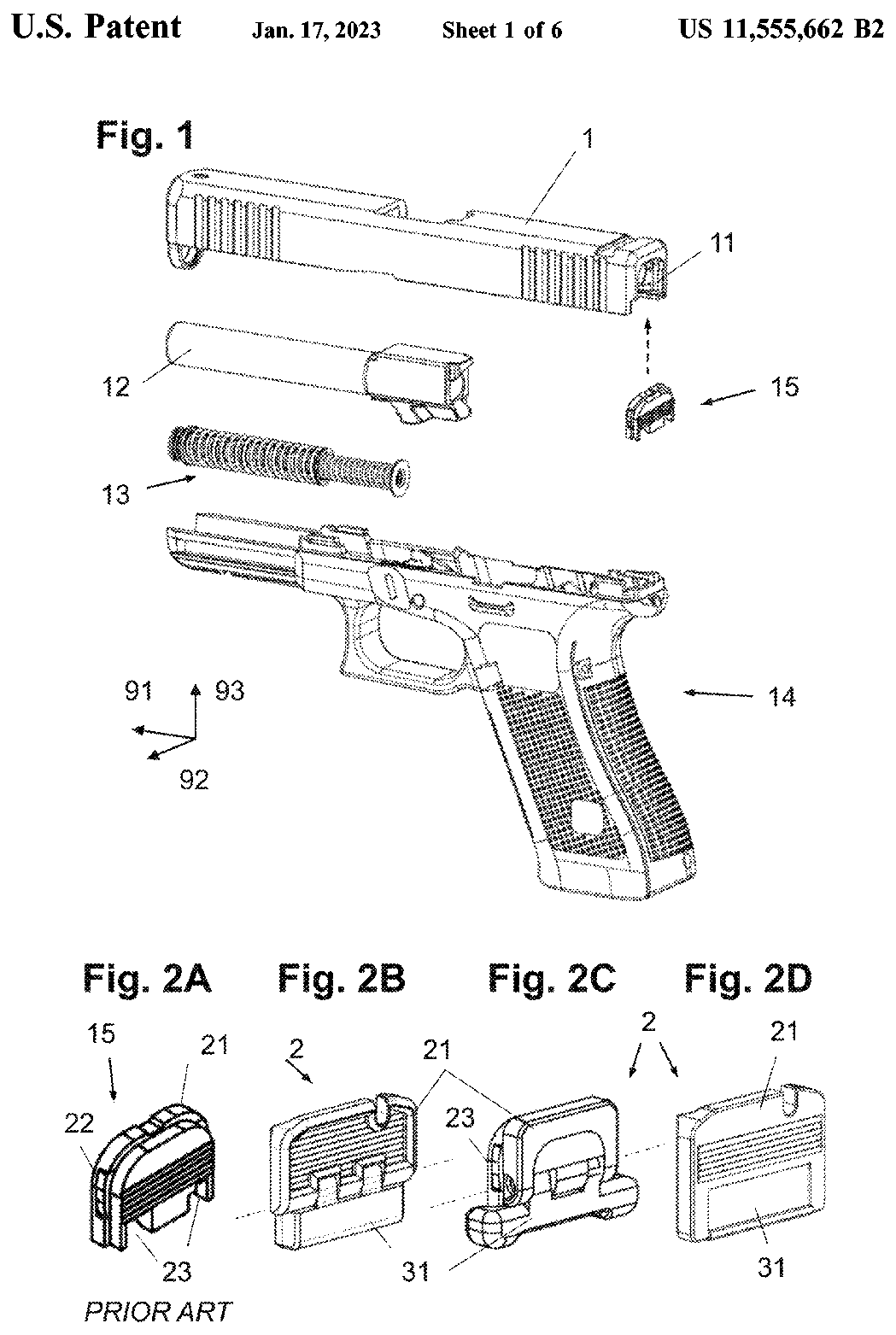
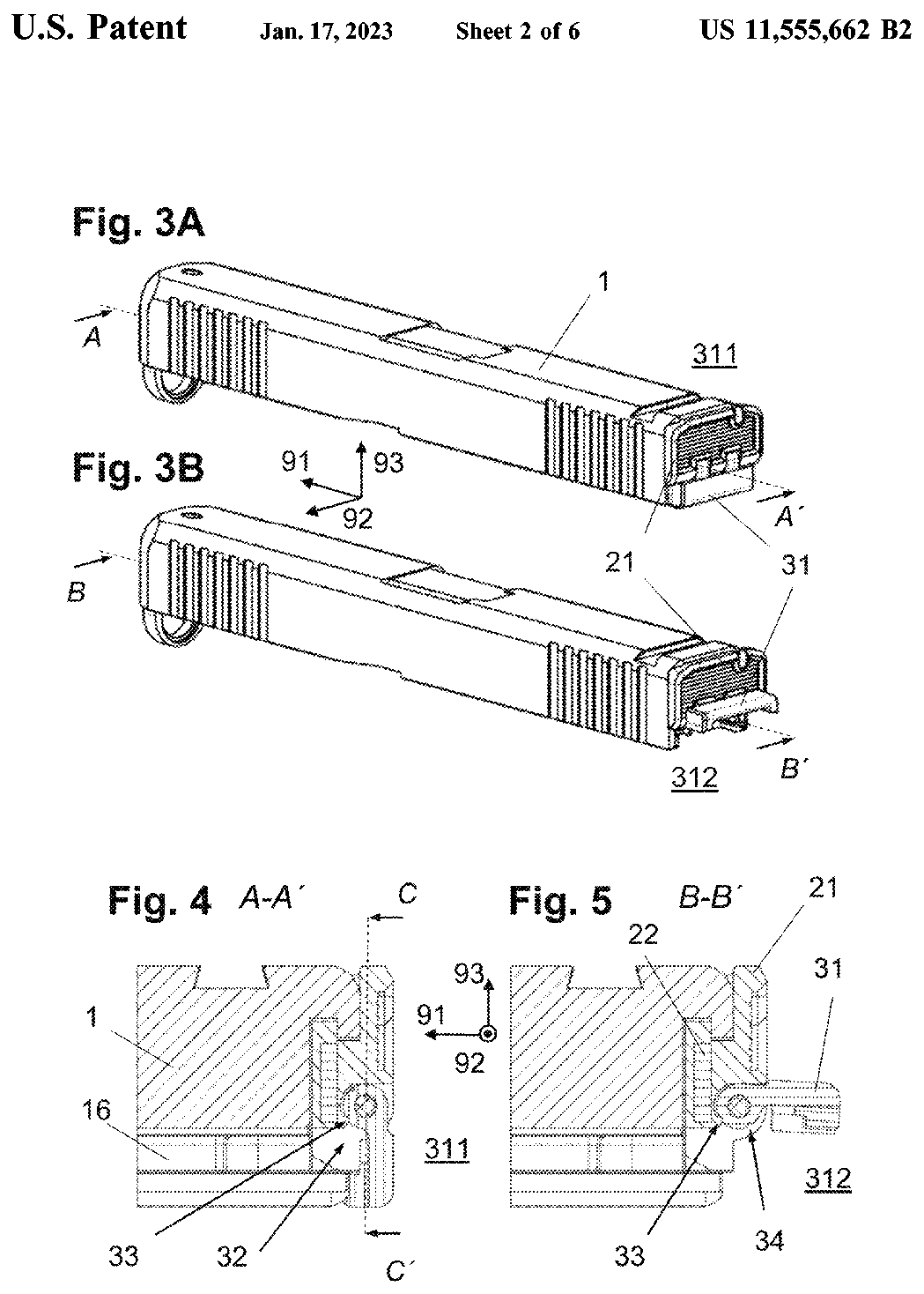
US Patent 11,555,662 — Multifunctional slide cover plate
Josef Kroyer, Leopold Oppenauer · assigned to Glock Technology GmbH · filed 2021-09-15 · granted 2023-01-17. Full patent (USPTO)
The slide cover plate at the rear of the slide, presented with an exploded view of the pistol's main assemblies (slide, barrel, recoil spring assembly, frame).
Why this is the Glock 22’s patent: listed on the maker’s patent-marking page — Virtual Patent Marking of GLOCK® Products (Version 1, Released: August, 2026) — GLOCK (linked as 'Patents' from the us.glock.com site footer), p. 1, row G22, column US11555662B2 eu-assets.contentstack.com [16]: “The following GLOCK® Products, the according models and product generations, and components thereof may be protected by one or more of the following Patents and Designs. … G22 … US11555662B2”
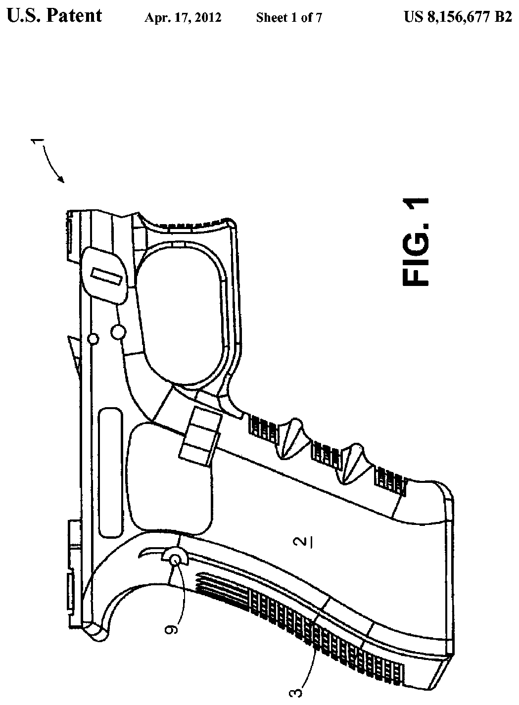
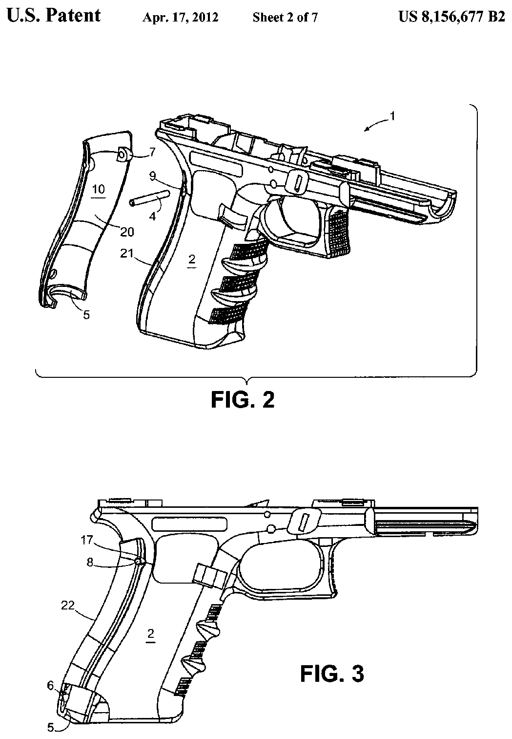
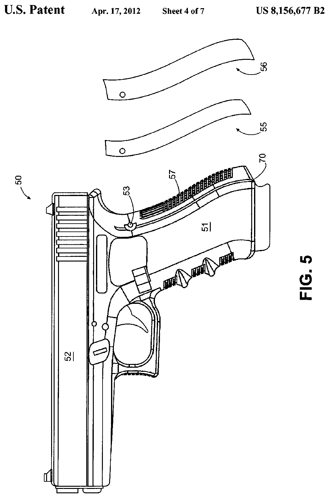
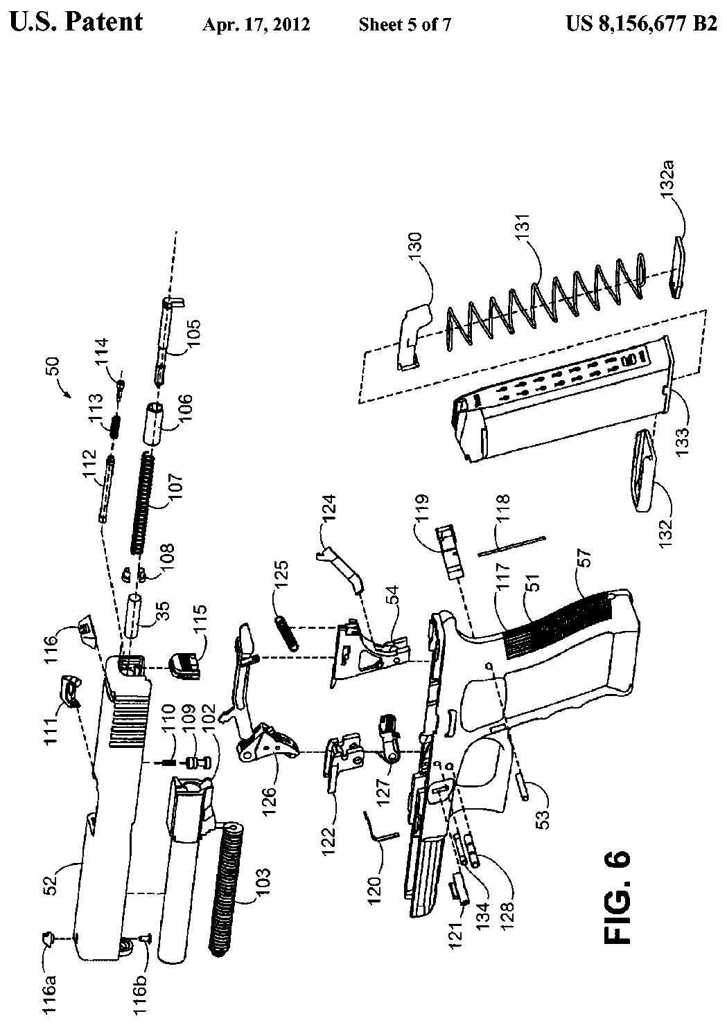
US Patent 8,156,677 — Assemblies and firearms incorporating such assemblies
Gaston Glock · filed 2010-04-15 · granted 2012-04-17. Full patent (USPTO)
The interchangeable backstrap on the polymer grip and the pin that both holds the backstrap and retains the trigger mechanism housing in the receiver, shown on a complete Glock-type pistol including a full exploded view.
Why this is the Glock 22’s patent: listed on the maker’s patent-marking page — Virtual Patent Marking of GLOCK® Products (Version 1, Released: August, 2026) — GLOCK (linked as 'Patents' from the us.glock.com site footer), p. 1, row G22, column US8156677B2 eu-assets.contentstack.com [16]: “The following GLOCK® Products, the according models and product generations, and components thereof may be protected by one or more of the following Patents and Designs. … G22 … US8156677B2”
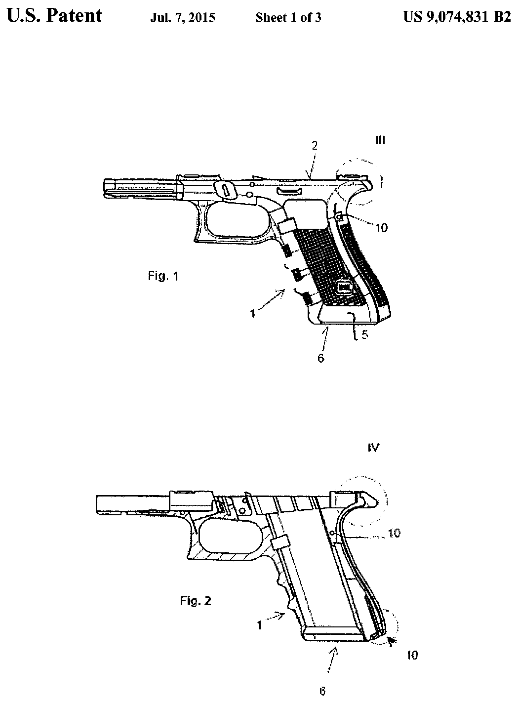
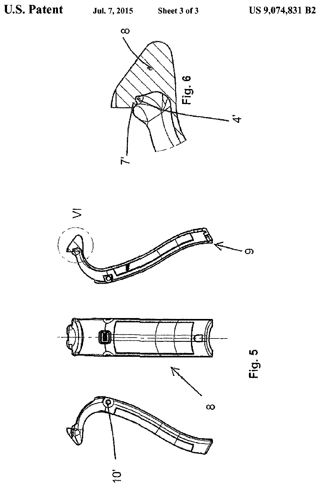
US Patent 9,074,831 — Receiver for a firearm
Gaston Glock · assigned to VALUE PRIVATSTIFTUNG (printed 'VALUE PRIVASTIFTUNG' on the patent) · filed 2013-07-05 · granted 2015-07-07. Full patent (USPTO)
The anchoring structures at the rear of the Glock receiver (cross-pin hole, lower edge, and the projection/indentation under the slide) that locate and hold an interchangeable backstrap.
Why this is the Glock 22’s patent: listed on the maker’s patent-marking page — Virtual Patent Marking of GLOCK® Products (Version 1, Released: August, 2026) — GLOCK (linked as 'Patents' from the us.glock.com site footer), p. 1, row G22, column US9074831B2 eu-assets.contentstack.com [16]: “The following GLOCK® Products, the according models and product generations, and components thereof may be protected by one or more of the following Patents and Designs. … G22 … US9074831B2”
Torque specifications
| Fastener | Torque | Sequence, notes and the source's words | Where it comes from |
|---|---|---|---|
| MOS adapter plate screws (2 × M3x6 Torx, T10) GLOCK pistol models in MOS configuration with GLOCK MOS Adapter Plates 01–08 (this model: G22 Gen5 MOS) |
1.5 N·m 13 in-lb · 1.1 ft-lb |
Field strip; place slide flat. Remove the GLOCK cover plate (the removed screws should not be used for fixing the adapter plates). Select the plate, markings facing up. Tighten the 2 screws (the set's M3x6 Torx screws, which come with a drop of glue applied). 'Make sure to use only these screws for fixing the adapter plates.' Verify tightness of the screws depending on ammunition and frequency of use; if you often screw on and unscrew, apply another drop of threadlocking adhesive to the screw threads. Threadlocker: Screws come with drop of glue applied; re-apply a drop of threadlocking type adhesive if screws are often removed “If a torque wrench is available the optimum fit is 1.5 Nm / 13.3 lbf. inch.” |
GLOCK MOS Adapter-Set (Modular Optic System) instruction sheet (© GLOCK 2020, 31798), linked from us.glock.com Owners Resources > Downloadable Materials as 'MOS Adapter Plate Instructions' — GLOCK, PDF p. 1 (Cleaning and Service > SERVICE eu-assets.contentstack.com [3] |
Reported by other sources — not the manufacturer
| Fastener | Torque | Who says so, and their words | Where it comes from |
|---|---|---|---|
| Front sight screw GLOCK pistols; Night Fision front sight with the Night Fision screw |
5–7 in-lb 0.56–0.79 N·m · 0.42–0.58 ft-lb |
Reported by Night Fision (sight maker) support knowledge base Threadlocker: "de-grease and apply high strength thread locker to the front sight screw when installing" (Night Fision screws come with thread locker pre-applied per its install guide) “The recommendation for a Glock front sight screw is to use 5-7 in/lbs. (0.565-0.791 N-m) of torque.” |
What is the Glock Front Sight Screw Torque Spec? — Night Fision (sight maker) support knowledge base nightfisionorg.freshdesk.com [4] |
| Front sight screw GLOCK pistols; Night Fision front sight with the Night Fision screw |
max. 10 in-lb 1.1 N·m · 0.83 ft-lb |
Reported by Night Fision (sight maker) support knowledge base “DO NOT EXCEED 10in/lbs. (1.13 N-m) of torque or risk of failure is very high.” |
What is the Glock Front Sight Screw Torque Spec? — Night Fision (sight maker) support knowledge base nightfisionorg.freshdesk.com [4] |
| Front sight screw GLOCK pistols; AmeriGlo front sight with AmeriGlo screw |
10 in-lb 1.1 N·m · 0.83 ft-lb |
Reported by AmeriGlo (sight maker) Hold the front blade square and firmly during final tightening; the screw must stay seated squarely in the head (sight most likely to rotate off-center then). Threadlocker: "a very small drop of Loctite on the end threads of the screw" “The screw should be tightened snugly (wrist-tight, 10 in-lbs) against the bottom of the slide.” |
Sight Installation Instructions — AmeriGlo (sight maker) ameriglo.com [5] |
| Optic plate to slide screws (M3 x 0.5 x 6 mm) Glock 22 MOS (Gen 4/5) with Forward Controls Design OPF-G, RMR plate (Trijicon RMR/SRO/RMR HD/RCR) |
13 in-lb 1.5 N·m · 1.1 ft-lb |
Reported by Forward Controls Design Threadlocker: VC-3 (Vibra-Tite) packet supplied with the plate “Plate to slide torque value: 13in/lb” |
OPF-G, RMR (product page) — Forward Controls Design forwardcontrolsdesign.com [6] |
| Optic (sight) to plate screws Glock 22 MOS (Gen 4/5) with Forward Controls Design OPF-G, RMR plate (Trijicon RMR/SRO/RMR HD/RCR) |
13 in-lb 1.5 N·m · 1.1 ft-lb |
Reported by Forward Controls Design “Sight to plate torque value: 13in/lb” |
OPF-G, RMR (product page) — Forward Controls Design forwardcontrolsdesign.com [6] |
| Optic plate to slide screws Glock 22 MOS with Forward Controls Design OPF-G, RMRcc plate (Trijicon RMRcc) |
13 in-lb 1.5 N·m · 1.1 ft-lb |
Reported by Forward Controls Design “Plate to slide: 13 in/lb.” |
OPF-G, RMRcc (product page) — Forward Controls Design forwardcontrolsdesign.com [7] |
| Optic (sight) to plate screws Glock 22 MOS with Forward Controls Design OPF-G, RMRcc plate (Trijicon RMRcc) |
18 in-lb 2 N·m · 1.5 ft-lb |
Reported by Forward Controls Design “Sight to plate: 18 in/lb.” |
OPF-G, RMRcc (product page) — Forward Controls Design forwardcontrolsdesign.com [7] |
| Optic plate to slide screws Glock 22 MOS (Gen 4/5) with Forward Controls Design OPF-G, ACRO plate |
13 in-lb 1.5 N·m · 1.1 ft-lb |
Reported by Forward Controls Design “Torque value for plate to slide: 13 in·lb.” |
OPF-G, ACRO / MPS (product page) — Forward Controls Design forwardcontrolsdesign.com [8] |
| Aimpoint ACRO P1/P2 mounting screw Glock 22 MOS (Gen 4/5) with Forward Controls Design OPF-G, ACRO plate, Aimpoint ACRO P1/P2 |
26 in-lb 2.9 N·m · 2.2 ft-lb |
Reported by Forward Controls Design “Torque value for ACRO P1/P2 mounting screw: 26 in·lb. For Steiner MPS, 18 in·lb. (updated by Steiner in 2024)” |
OPF-G, ACRO / MPS (product page) — Forward Controls Design forwardcontrolsdesign.com [8] |
| Steiner MPS mounting screw Glock 22 MOS (Gen 4/5) with Forward Controls Design OPF-G, ACRO plate, Steiner MPS |
18 in-lb 2 N·m · 1.5 ft-lb |
Reported by Forward Controls Design “Torque value for ACRO P1/P2 mounting screw: 26 in·lb. For Steiner MPS, 18 in·lb. (updated by Steiner in 2024)” |
OPF-G, ACRO / MPS (product page) — Forward Controls Design forwardcontrolsdesign.com [8] |
| Optic plate to slide screws (M3 x 0.5 x 6 mm) Glock 22 MOS with Forward Controls Design OPF-G, EFLX plate (EOTech EFLX) |
13 in-lb 1.5 N·m · 1.1 ft-lb |
Reported by Forward Controls Design “Plate to slide: 13in/lb” |
OPF-G, EFLX (product page) — Forward Controls Design forwardcontrolsdesign.com [9] |
| Optic (sight) to plate screws Glock 22 MOS with Forward Controls Design OPF-G, EFLX plate (EOTech EFLX) |
20–25 in-lb 2.3–2.8 N·m · 1.7–2.1 ft-lb |
Reported by Forward Controls Design “Sight to plate: 20 to 25 in/lb” |
OPF-G, EFLX (product page) — Forward Controls Design forwardcontrolsdesign.com [9] |
| Optic plate mounting screws (M3 x 6 mm FH) Glock 22 MOS with C&H Precision V4 MIL/LEO adapter plate (RMR footprint) |
12–15 in-lb 1.4–1.7 N·m · 1–1.2 ft-lb |
Reported by C&H Precision Weapons “Qty 3 – M3 x 6 MM FH Plate Mounting Screws, Torque between 12-15in/lbs” |
V4 MIL/LEO Adapter Trijicon RMR / RMR HD / SRO / Holosun 407C / 507C / 507Comp / 508T ... Fits GLOCK MOS (product page) — C&H Precision Weapons chpws.com [10] |
| Optic to plate screws, Trijicon RMR (4-40 x .320 FHB) Glock 22 MOS with C&H Precision V4 MIL/LEO adapter plate (RMR footprint), Trijicon RMR |
12–15 in-lb 1.4–1.7 N·m · 1–1.2 ft-lb |
Reported by C&H Precision Weapons “Qty 3 – 4-40 x .320 FHB Trijicon RMR Optic Mounting Screws, Torque between 12-15in/lbs” |
V4 MIL/LEO Adapter Trijicon RMR / RMR HD / SRO / Holosun 407C / 507C / 507Comp / 508T ... Fits GLOCK MOS (product page) — C&H Precision Weapons chpws.com [10] |
| Optic to plate screws, Holosun 507C/508T (4-40 x .280 FHB) Glock 22 MOS with C&H Precision V4 MIL/LEO adapter plate (RMR footprint), Holosun 507C/508T |
12–15 in-lb 1.4–1.7 N·m · 1–1.2 ft-lb |
Reported by C&H Precision Weapons “Qty 3 – 4-40 x .280 FHB Holosun 507C / 508T Optic Mounting Screws, Torque between 12-15in/lbs” |
V4 MIL/LEO Adapter Trijicon RMR / RMR HD / SRO / Holosun 407C / 507C / 507Comp / 508T ... Fits GLOCK MOS (product page) — C&H Precision Weapons chpws.com [10] |
| Optic adapter plate mounting screws (Holosun RMR-footprint plate for Glock MOS) Glock 22 MOS with HOLOSUN adapter plate for RMR footprint (Holosun 407C/507C/508T, Trijicon RMR) |
1.4 N·m 12 in-lb · 1 ft-lb |
Reported by HOLOSUN Europe (holosun.eu, operated by Picotronic GmbH, HOLOSUN European distributor) “Tightening torque recommended: 1,4 Nm” |
Adapter plate for Glock MOS (except 43/43X/48 MOS), for RMR footprint (product page) — HOLOSUN Europe (holosun.eu, operated by Picotronic GmbH, HOLOSUN European distributor) holosun.eu [11] |
| Optic adapter plate mounting screws (Holosun RMR-footprint plate for Glock MOS) Glock 22 MOS with HOLOSUN adapter plate for RMR footprint (Holosun 407C/507C/508T, Trijicon RMR) |
max. 1.7 N·m 15 in-lb · 1.3 ft-lb |
Reported by HOLOSUN Europe (holosun.eu, operated by Picotronic GmbH, HOLOSUN European distributor) “tightening torque Maximum: 1,7 Nm” |
Adapter plate for Glock MOS (except 43/43X/48 MOS), for RMR footprint (product page) — HOLOSUN Europe (holosun.eu, operated by Picotronic GmbH, HOLOSUN European distributor) holosun.eu [11] |
| Optic adapter plate mounting screws (Holosun K/EPS-footprint plate for Glock MOS) Glock 22 MOS with HOLOSUN adapter plate for 407K/507K/EPS Carry/EPS |
1.4 N·m 12 in-lb · 1 ft-lb |
Reported by HOLOSUN Europe (holosun.eu, operated by Picotronic GmbH, HOLOSUN European distributor) “Tightening torque recommended: 1,4 Nm” |
Adapter plate for Glock MOS (except 43X/48 MOS), compatible with Holosun 407K/507K/EPS Carry/EPS (product page) — HOLOSUN Europe (holosun.eu, operated by Picotronic GmbH, HOLOSUN European distributor) holosun.eu [12] |
| Optic adapter plate mounting screws (Holosun K/EPS-footprint plate for Glock MOS) Glock 22 MOS with HOLOSUN adapter plate for 407K/507K/EPS Carry/EPS |
max. 1.7 N·m 15 in-lb · 1.3 ft-lb |
Reported by HOLOSUN Europe (holosun.eu, operated by Picotronic GmbH, HOLOSUN European distributor) “tightening torque Maximum: 1,7 Nm” |
Adapter plate for Glock MOS (except 43X/48 MOS), compatible with Holosun 407K/507K/EPS Carry/EPS (product page) — HOLOSUN Europe (holosun.eu, operated by Picotronic GmbH, HOLOSUN European distributor) holosun.eu [12] |
| Red-dot optic mounting screws (6-32 flat head, supplied) into EGW rear-dovetail sight mount Glock 22 (non-MOS slide only; EGW: 'Does not fit ANY/ALL Glock MOS models') with the EGW 'Trijicon RMR / SRO, Holosun 407c / 507c Sight Mount for Glock' (replaces the rear sight; for Trijicon RMR/SRO, |
15 in-lb 1.7 N·m · 1.2 ft-lb |
Reported by Evolution Gun Works (EGW) Remove the rear sight, install the EGW mount in the dovetail, tighten the set screw if applicable, place the optic on the mount, then apply blue Loctite and torque the optic screws. Threadlocker: Blue Loctite on the provided mounting screws (EGW instructions) “Torque mounting screws to 15in/lbs” |
Trijicon RMR / SRO, Holosun 407c / 507c Sight Mount for Glock (EGW product page, installation instructions section) — Evolution Gun Works (EGW) egwguns.com [13] |
| Red-dot optic mounting screws (supplied) into EGW rear-dovetail sight mount (Docter/Venom/Viper/FastFire footprint) Glock 22 (non-MOS slide only; EGW: 'Does not fit ANY/ALL Glock MOS models') with the EGW 'Glock Red Dot Mount | Fits Vortex Venom, Viper & Burris FastFire | EGW' (replaces the rear sight) |
15 in-lb 1.7 N·m · 1.2 ft-lb |
Reported by Evolution Gun Works (EGW) Remove the rear sight, install the EGW mount in the dovetail, tighten the set screw if applicable, place the optic on the mount, then apply blue Loctite and torque the optic screws. Threadlocker: Blue Loctite on the provided mounting screws (EGW instructions) “Torque mounting screws to 15 in/lbs” |
Glock Red Dot Mount | Fits Vortex Venom, Viper & Burris FastFire | EGW (EGW product page, installation instructions section) — Evolution Gun Works (EGW) egwguns.com [14] |
| DeltaPoint Pro M4x.7x15.8mm Torx screws through Leupold mount base into dovetail Glock 22 (rear-sight dovetail slide) with Leupold DeltaPoint Pro on the Leupold Glock base/dovetail (SKU 170906) |
25 in-lb 2.8 N·m · 2.1 ft-lb |
Reported by Leupold & Stevens, Inc. Remove the rear sight, fit the Leupold dovetail (part number up) in its place, set the mount base over it, seat the DeltaPoint Pro on the base posts, then torque the two Torx screws (press-fit). “Secure the screws by applying 25 in-lbs of torque.” |
Leupold DeltaPoint Pro Reflex Sight — Operating Instructions (Part #120278, artwork #120279P; English text with French translation) — Leupold & Stevens, Inc., PDF p. 1 (Installation section; mount li leupold.com [15] |
Materials and factory finish
As stated by Glock Ges.m.b.H.. Prep, masking and cure depend on these; a polymer or aluminium part, a nitrided or anodised finish, and a blued steel part are each a different job. Variants with other finishes may exist — check the maker's page for the exact SKU on the bench.
| Component | Material | Factory finish | Where it comes from |
|---|---|---|---|
| Frame G22 Gen5 | polymer | — | GLOCK Owner's Manual — Models G17 to G48 (Instructions for Use) — GLOCK Ges.m.b.H. eu-assets.contentstack.com [1] “FRAME: The frame (17) is made of polymer with hardened steel guides.” |
| Slide G22 Gen5 | — | matte black | GLOCK Owner's Manual — Models G17 to G48 (Instructions for Use) — GLOCK Ges.m.b.H. eu-assets.contentstack.com [1] “SLIDE: The advanced surface treatment of the slide (1) results in optimal hardness by considerably reducing wear and tear and it makes it corrosion resistant, even when operating in saltwater conditions. The matte black surface minimizes light reflection – an advantage in tactical circumstances.” |
| Sights standard front sights (steel sights optional) | polymer | — | GLOCK Owner's Manual — Models G17 to G48 (Instructions for Use) — GLOCK Ges.m.b.H. eu-assets.contentstack.com [1] “All GLOCK pistol models come standard with polymer front sights (16a), which provide excellent damping characteristics on impact. Steel front sights with a white contrast point, steel luminescent sights and steel night sights with a self-illuminating tritium contrast point are available as options.” |
Function check
- Confirm the pistol is unloaded with no magazine inserted before each test.
- TRIGGER SAFETY TEST: with the trigger safety not depressed, the safety should prevent rearward movement of the trigger and the pistol should not dry fire.
- TRIGGER RESET TEST: with the muzzle in a safe direction, pull the trigger — you should hear and feel the firing pin release. Hold the trigger back, rack the slide, then release the trigger; it should reset to its forward position. Repeat this several times.
- SLIDE LOCK-OPEN TEST: insert an empty magazine, pull the slide fully to the rear, and confirm the slide locks open. Repeat with each of your magazines.
- With the slide in battery, push forward firmly on the muzzle. The pistol must not fire out of battery.
- Confirm the magazine drops free when the release is pressed.
Maintenance
Lubrication points
- Four frame rail contact points on the slide
- Barrel hood and the top of the barrel lug
- Outside of the barrel where it rides in the front of the slide
- The rear lug cut where the recoil spring assembly bears
Cleaning notes
Glock specifies a very light application of lubricant — roughly one drop per point. Over-lubrication attracts carbon. Keep the striker channel dry and free of solvent.
Suggested inspection interval: roughly every 5000 rounds. This is a general guideline, not a manufacturer specification.
Wear parts to inspect
Recoil spring assembly · Extractor · Slide lock spring · Magazine springs and followers · Trigger spring
Common issues
| Symptom | Likely cause | What to do |
|---|---|---|
| Slide will not come off after pulling the slide lock down | Trigger not pressed after the last rack, or the slide retracted too far | Return the slide to battery, verify the chamber is empty, press the trigger, then retract only about 1/8 in. |
| Recoil spring assembly falls out during reassembly | Assembly resting on the barrel rather than seated in the barrel lug cut | Reseat it in the half-moon cut on the underside of the barrel lug. |
| Erratic ejection or brass to the face | Worn recoil spring assembly, extractor, or ejector | Replace the recoil spring assembly first as the cheapest variable, then inspect the extractor and ejector. see a gunsmith |
Similar manual of arms
Legal notes
Sourcing
- Confidence
- high — Cross-checked against a primary source such as the manufacturer's manual or an issuing military technical manual.
- Verification
- Checked against the manufacturer manual
- Last updated
- 2026-10-29
References
Every source this page draws on, with its web address so you can read it yourself. Numbers in brackets elsewhere on the page point here.
- [1] GLOCK Owner's Manual — Models G17 to G48 (Instructions for Use) — GLOCK Ges.m.b.H. manufacturer manual primary source
https://eu-assets.contentstack.com/v3/assets/bltf7171cc1cfc1a31f/bltebc27f0f8099f9f4/6a3bd649918bcf1447c2f9f6/54774_Instructions-for-use_Relaunch_Standard_g17-48-BT01_02a_062026-GLOCK-Inc.pdf (checked 2026-09-14) - [2] GLOCK Owner's Resources — Downloadable Materials — GLOCK Ges.m.b.H. manufacturer manual primary source
https://us.glock.com/en/owners-resources/downloadable-materials (checked 2026-09-14) - [3] GLOCK MOS Adapter-Set (Modular Optic System) instruction sheet (© GLOCK 2020, 31798), linked from us.glock.com Owners Resources > Downloadable Materials as 'MOS Adapter Plate Instructions' — GLOCK manufacturer manual primary source
https://eu-assets.contentstack.com/v3/assets/bltf7171cc1cfc1a31f/blt06337d8ec5ed9ac8/68f7dfbab497b1ddaede6b66/MOS_Instructions_21422.pdf (checked 2026-09-27) - [4] What is the Glock Front Sight Screw Torque Spec? — Night Fision (sight maker) support knowledge base website secondary source
https://nightfisionorg.freshdesk.com/support/solutions/articles/154000142823-what-is-the-glock-front-sight-screw-torque-spec- (checked 2026-09-27) - [5] Sight Installation Instructions — AmeriGlo (sight maker) website secondary source
https://www.ameriglo.com/support/sight-installation-instructions (checked 2026-09-27) - [6] OPF-G, RMR (product page) — Forward Controls Design website secondary source
https://www.forwardcontrolsdesign.com/OPF-G-RMR_p_224.html (checked 2026-09-27) - [7] OPF-G, RMRcc (product page) — Forward Controls Design website secondary source
https://www.forwardcontrolsdesign.com/OPF-G-RMRcc_p_318.html (checked 2026-09-27) - [8] OPF-G, ACRO / MPS (product page) — Forward Controls Design website secondary source
https://www.forwardcontrolsdesign.com/OPF-G-ACRO-MPS_p_265.html (checked 2026-09-27) - [9] OPF-G, EFLX (product page) — Forward Controls Design website secondary source
https://www.forwardcontrolsdesign.com/OPF-G-EFLX_p_459.html (checked 2026-09-27) - [10] V4 MIL/LEO Adapter Trijicon RMR / RMR HD / SRO / Holosun 407C / 507C / 507Comp / 508T ... Fits GLOCK MOS (product page) — C&H Precision Weapons website secondary source
https://chpws.com/product/glock-mos-v4-mil-leo-to-holosun-407c-507c-508c-508t/ (checked 2026-09-27) - [11] Adapter plate for Glock MOS (except 43/43X/48 MOS), for RMR footprint (product page) — HOLOSUN Europe (holosun.eu, operated by Picotronic GmbH, HOLOSUN European distributor) website secondary source
https://www.holosun.eu/en/p/70189520 (checked 2026-09-27) - [12] Adapter plate for Glock MOS (except 43X/48 MOS), compatible with Holosun 407K/507K/EPS Carry/EPS (product page) — HOLOSUN Europe (holosun.eu, operated by Picotronic GmbH, HOLOSUN European distributor) website secondary source
https://www.holosun.eu/en/p/70189513 (checked 2026-09-27) - [13] Trijicon RMR / SRO, Holosun 407c / 507c Sight Mount for Glock (EGW product page, installation instructions section) — Evolution Gun Works (EGW) website secondary source
https://egwguns.com/trijicon-rmr-sro-holosun-407c-507c-mount-for-glock (checked 2026-10-11) - [14] Glock Red Dot Mount | Fits Vortex Venom, Viper & Burris FastFire | EGW (EGW product page, installation instructions section) — Evolution Gun Works (EGW) website secondary source
https://egwguns.com/vortex-viper-venom-glock-sight-mount-fits-burris-fastfire-and-docter (checked 2026-10-11) - [15] Leupold DeltaPoint Pro Reflex Sight — Operating Instructions (Part #120278, artwork #120279P; English text with French translation) — Leupold & Stevens, Inc. manufacturer manual secondary source
https://www.leupold.com/media/manuals/DeltaPoint_Pro_Manual_French_120279P.pdf (checked 2026-10-11) - [16] Virtual Patent Marking of GLOCK® Products (Version 1, Released: August, 2026) — GLOCK (linked as 'Patents' from the us.glock.com site footer) website primary source
https://eu-assets.contentstack.com/v3/assets/bltf7171cc1cfc1a31f/blt1ccd0bce687f1446/6a732cbdd920822d940ca846/Virtual-Patent-Marking_20260805.pdf (checked 2026-10-13) - [17] GLOCK Armorer's Manual (2013), archive.org scan — GLOCK Ges.m.b.H. (scan hosted on archive.org) manufacturer manual primary source
https://archive.org/details/glock-armorer-v-2013_202406 (checked 2026-10-29) - [18] Disassembly Guide: Glocks — Apex Gunsmithing website secondary source
https://apexgunsmithing.com/disassembly-guide-glocks/ (checked 2026-10-29)
Notes: Verified against the factory manual on 2026-09-14. The procedure as previously written was confirmed correct, including the 1/8 in (3 mm) slide retraction. Detail added from the manual: the reason over-retracting fails is that it resets the trigger forward; the barrel comes out by pushing it toward the front of the slide and then up and rearward; the recoil spring assembly seats in the second semi-circular notch on the barrel locking cams; and safety glasses are required. Field strip and reassembly are identical across the Glock line and unchanged between generations; only internal parts differ. The .40 S&W models run at higher slide velocity than 9mm. Recoil spring assemblies wear faster and are a common source of erratic ejection when tired.