← All firearms · Printable work order
Mossberg 500 / 590
- easy
- Shop tier 1
- high confidence
- Shotgun
- pump action
- tube magazine
- tang safety
- home defense
- workhorse
field strip ~3 min · reassembly ~5 min · detail strip ~25 min
Specifications
- Manufacturer
- O.F. Mossberg & Sons
- Origin
- United States
- Category
- Shotgun
- Action
- Pump action
- Calibers
- 12 gauge, 20 gauge, .410 bore
- Capacity
- 5+1 typical on the 500, 8+1 on many 590 configurations
- Production
- 1960–present (in-production)
- Also known as
- Mossberg 500, Mossberg 590, Mossberg 590A1, Maverick 88 (similar)
Model-specific safety
- Unloading a tube magazine takes several cycles of the action. The manual specifies checking three places before disassembly: the chamber, the elevator, and the magazine tube.
- Wear eye protection during disassembly and cleaning. The manual calls for it specifically — there are spring-loaded components and oil splatter.
- Do not pull the trigger and allow the hammer to fall while the trigger housing assembly is out of the receiver. The manual warns this can cause personal injury and damage to the assembly.
- The trigger housing assembly is a complex assembly and must not be disassembled. The manual restricts that to an authorised Product Service Center or a qualified gunsmith.
- The 500 and the 590 differ in how the barrel is retained: the 500, 505, 510 and 535 use a takedown screw through the end of the magazine tube, while the 590 and 835 use a magazine cap. Identify which you have before starting.
- On 590 and 835 models the magazine spring retainer and spring are under significant spring pressure when the magazine cap comes off.
- The tang safety sits on top of the receiver. It blocks the trigger but is not a substitute for clearing the gun.
Under spring tension
- Magazine tube spring and follower
- Hammer spring in the trigger housing
Easily lost parts
Trigger housing retainer pin · Takedown screw or magazine cap · Cartridge stop and cartridge interrupter · Bolt slide · Elevator
Tools
| Tool | Required | Used for | Substitute |
|---|---|---|---|
| Punch (roughly 1/8 in) | Optional | Pushing out the trigger housing pin if tight. | |
| Flat-blade screwdriver or coin | Optional | Turning the takedown screw on 500-series guns. |
Shop difficulty
Shop tier 1 Tier 1 — easy among shotguns, for the full job: strip to the parts that get coated and put it back together working. About 51 listed items (several are pre-assembled groups) that mostly slip in and out once the trigger housing pin is pushed; the traps are an alignment puzzle (bolt slide and action bars) and the hammer-cocked/safety-on order, not held springs. Removing the magazine tube for a bare receiver needs only a strap wrench and the forend nut a tube-nut tool.
Parts: 51 numbered parts (Generic parts list for the whole 500/505/510/535/590/835 pump family, including optional stocks and accessories; trigger housing and bolt are listed as assemblies), from Owner's Manual for 500, 505, 510, 535, 590 and 835 Pump Action Shotguns — O.F. Mossberg & Sons, Inc., p. 34 resources.mossberg.com [1].
Bench time: about 30 min to strip, 45 min to rebuild (estimate). Detail strip of receiver, bolt and forend; trigger housing kept as a unit unless coated. Rebuild longer for the bolt slide/action-bar alignment and tang safety detent.
Small parts: 1 pins, 2 springs, 0 detents or plungers (counted from the parts list in partCount (entry partsList): rows whose names contain pin / spring / detent, plunger or ball, quantities applied; a detent spring counts as a spring)
What comes off for coating
- Barrel and magazine: barrel (takedown screw or magazine cap), magazine spring retainer, spring and follower, magazine tube from receiver (optional) — strap wrench, padded vise
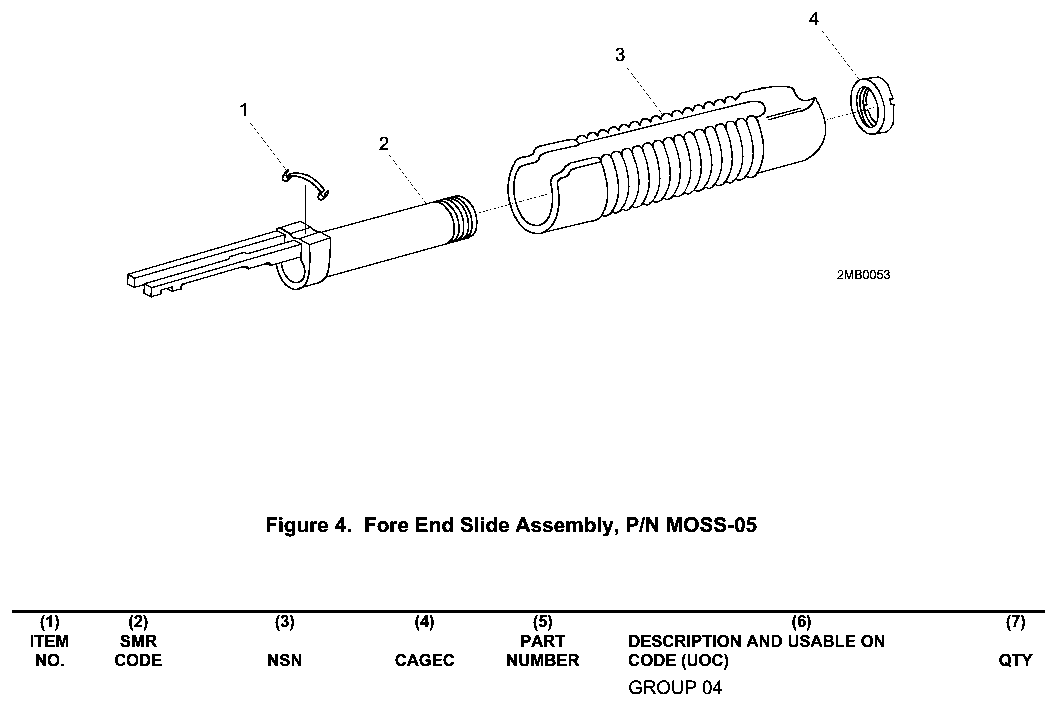
- Forend / action slide: action slide tube nut, forend, anti-rattle spring — tube nut tool
- Receiver: trigger housing pin and trigger housing, elevator, cartridge stop and interrupter, bolt and bolt slide, ejector and ejector screw, safety button screw, safety button, detent plate, detent ball and spring
- Bolt: bolt lock pin and bolt lock, extractor pins, extractors and springs, firing pin retaining pin, firing pin, washer and spring
- Trigger housing: hammer, trigger, sear and disconnector group on their pins (only if the housing itself is being coated; Mossberg advises
- Stock / grip: recoil pad screws and pad, stock bolt, lock washer and washer — long 1/2 in. or 13 mm socket on extension
Special tools
- Tube nut tool — Forend action slide tube nut
- Strap wrench and padded vise — Magazine tube off the receiver
- Long socket extension — Stock bolt deep in the buttstock
- Roll/pin punches 1/16-1/8 in. — Bolt extractor and firing pin pins
Known pain points
- The bolt, bolt slide and both action slide bars have to go back in the same relationship they came out; a bar out of its cut or a bolt slide offered at the wrong point of forend travel will not drop in or binds the action. (reassembly)
Source: Owner's Manual for 500, 505, 510, 535, 590 and 835 Pump Action Shotguns — O.F. Mossberg & Sons, Inc. resources.mossberg.com [1] — “Pay special attention to the position of the bolt, bolt slide and action slide bar assembly during this portion of the disassembly, as the parts must be in the same relationship during reassembly.” - Owners report the shell stop and interrupter get jammed in wrong and the action bars mis-seated when the gun is forced together; it only runs once everything lines up. (reassembly)
Owners report: Seeking help from someone who owns a Mossberg 500 in the Bay Area — Calguns.net calguns.net [9] — “mossbergs are great but they can be harder to put back together. it sounds like the action bars are not in the right spot. also i will bet the shell stop and interrupter are jammed in wrong.” - The hammer must be at full cock to get the trigger housing back in, and the safety must be on to reinstall the bolt; neither is obvious and forcing it damages parts. (reassembly)
Source: The Mossberg Model 500: History & Disassembly — American Rifleman (NRA) americanrifleman.org [10] — “Be aware that the hammer must be in the full-cock position for reinsertion of the trigger assembly and that the safety must be in the “on” position to re-install the bolt assembly.” - Getting the receiver bare means unscrewing the magazine tube from the receiver, which the Army does with the receiver in a capped vise and a strap pipe wrench. (both)
Source: TM 9-1005-338-13&P: Technical Manual, Unit and Direct Support Maintenance (including Repair Parts and Special Tools List) for Mossberg 12-Gauge Shotgun, Model 500 (1005-01-295-1832) and Mossberg 12-Gauge Shotgun, Model 590 (1005-01-251-8578) — Headquarters, Department of the Army archive.org [3] — “Place strap style pipe wrench around magazine tube assembly (2) and turn to the left (counterclockwise),” - The action slide tube nut that holds the forend on is removed and refitted with a dedicated tube nut tool. (both)
Source: TM 9-1005-338-13&P: Technical Manual, Unit and Direct Support Maintenance (including Repair Parts and Special Tools List) for Mossberg 12-Gauge Shotgun, Model 500 (1005-01-295-1832) and Mossberg 12-Gauge Shotgun, Model 590 (1005-01-251-8578) — Headquarters, Department of the Army archive.org [3] — “Using tube nut tool, remove slide tube nut (1) from action slide assembly (2).”
Fit or check on rebuild
- Magazine tube torqued and aligned to the barrel lug — Tube carries the barrel; it is refitted hand-tight-plus with a strap wrench and must line up with the takedown screw or cap.
Source: TM 9-1005-338-13&P: Technical Manual, Unit and Direct Support Maintenance (including Repair Parts and Special Tools List) for Mossberg 12-Gauge Shotgun, Model 500 (1005-01-295-1832) and Mossberg 12-Gauge Shotgun, Model 590 (1005-01-251-8578) — Headquarters, Department of the Army archive.org [3] — “Place strap style pipe wrench around magazine tube assembly (2) and turn to the left (counterclockwise),” - Safety detent feel — The tang safety's ball and spring under the detent plate set the click; a missing ball gives a loose safety.
- Function check: safety, trigger/sear release, disconnector and feeding with dummy rounds — Standard after any detail strip; a mis-assembled sear or disconnector can double or fail to fire.
This is Pew-Takedown's rating, not the manufacturer's. How tiers are rated. Forum reports are owners' experience, not specifications.
Manufacturer videos
Official videos from O.F. Mossberg & Sons's own channels, linked rather than copied. Where a video and the steps on this page differ, follow the manufacturer's manual and video.
- Loading and Unloading - Mossberg 500 / 590 Series Shotguns MOSSBERG
clearing, operation · 2020-05-12
Covers: Mossberg 500 / 590 series pump-action shotguns (per title and description) - How Mossberg 500/590 Pump-Action Shotguns Work MOSSBERG
operation · 2024-06-18
Covers: Mossberg 500 and 590 pump-action shotguns (per description) - Gun Part Nomenclature - Mossberg 500 / 590 Series Shotguns MOSSBERG
operation · 2020-05-12
Covers: Mossberg 500 / 590 series pump-action shotguns (per title and description)
Procedures
Clear and Make Safe
Clear & Make SafeManufacturer’s video: Loading and Unloading - Mossberg 500 / 590 Series Shotguns MOSSBERG
- Point the muzzle in a safe direction and keep your finger off the trigger.
- Move the safety button fully rearward to the ON (safe) position.
- Depress the action lock lever on the left side behind the trigger guard and pull the forearm rearward to open the action.Removed at this step:
Chambered shell, if present - Cycle the action repeatedly, catching each shell as it ejects, until no more shells feed from the magazine tube.
- With the action open, visually and physically check the chamber, the elevator, and the magazine tube.WarningThree places, not two. The manual names the chamber, the elevator, and the magazine tube specifically.
- Remove all live ammunition from the work area, and put on eye protection before going further.
Field Strip
Field Strip tools requiredBarrel and trigger housing. Verified against the factory manual — note the bolt-position step before the barrel comes off, and that the barrel rotates out rather than pulling straight.
- Complete the Clear and Make Safe procedure and put on eye protection.
- Depress the action lock lever and open the action by sliding the forearm fully rearward.
- Move the forearm slowly forward from the fully rearward position until the front of the bolt sits in the middle of the ejection port.WarningDo not skip this. The barrel will not come out cleanly unless the bolt is positioned here first.TipThis is the step most commonly left out of informal instructions for this shotgun.
- On a 590 or 835, unscrew the magazine cap counterclockwise. On a 500, 505, 510 or 535, loosen the takedown screw counterclockwise until its threads are completely disengaged from the end of the magazine tube.WarningOn 590 and 835 models the magazine spring retainer and spring are under significant spring pressure.Removed at this step:
Magazine cap or takedown screw - Remove the barrel from the receiver with a gentle back-and-forth rotational movement while pulling it out of the receiver assembly.TipRotate as you pull. Pulling straight out is the common mistake.Removed at this step:
Barrel - Position the shotgun on a clean surface with the trigger guard upward.
- Using a punch no greater than 3/16 in (4.76 mm) in diameter, push out the small-diameter trigger housing retainer pin from the side of the receiver, roughly 1/2 in (12.7 mm) below the rear of the trigger guard.Removed at this step:
Trigger housing retainer pin - Remove the trigger housing assembly by lifting the rear portion upward first.WarningOnce the trigger housing is out of the receiver, do not pull the trigger and let the hammer fall. The manual warns this can injure you and damage the assembly.Removed at this step:
Trigger housing assembly - Stop here for routine cleaning. The trigger housing assembly itself must not be disassembled — the manual restricts that to an authorised service centre or a qualified gunsmith.
Disassembly of Internal Receiver Components
Detail StripBeyond routine cleaning. Study how the parts sit before removing them — they must go back in the same relationship.
- Complete the field strip, with the trigger housing assembly removed.WarningBefore going further, study how the internal components are arranged inside the receiver. The manual asks for this explicitly.
- Remove the cartridge interrupter and cartridge stop from the receiver.TipIt may be necessary to tap the sides of the receiver lightly to release these parts. On left-hand models they sit in the same positions but the ejection port is on the opposite side.Removed at this step:
Cartridge interrupterCartridge stop - Move the forearm and action slide assembly rearward until the bolt assembly and bolt slide are three quarters of the way rearward.WarningPay attention to the position of the bolt, bolt slide, and action slide bar assembly — they must be in the same relationship on reassembly.
- When the bottom of the bolt slide aligns with the clearance cuts in the sides of the receiver, lift the bolt slide upward and out of the receiver.Removed at this step:
Bolt slide - Remove the bolt assembly by sliding it forward and out of the receiver through the barrel opening at the front.Removed at this step:
Bolt assembly - With the safety button fully rearward in the ON position, pivot the front portion of the elevator upward out of the receiver and squeeze its arms together to free it.WarningThe safety must be fully rearward in the ON position for the elevator assembly to come out.Removed at this step:
Elevator
Disassemble the fore end assembly
Detail Strip tools required gunsmith recommendedRemoves the slide tube nut with the fabricated tube nut tool, then slides the slide grip and anti-rattle spring off the action slide assembly (WP 0023 00). The manual puts this in Chapter 3, Unit Maintenance, with the small arms repairman tool kit; the Maintenance Allocation Chart (WP 0034 00) lists Repair of this group at direct support (F).
Follows TM 9-1005-338-13&P: Technical Manual, Unit and Direct Support Maintenance (including Repair Parts and Special Tools List) for Mossberg 12-Gauge Shotgun, Model 500 (1005-01-295-1832) and Mossberg 12-Gauge Shotgun, Model 590 (1005-01-251-8578) — Headquarters, Department of the Army, p. WP 0023 00, p. 0023 00-1 archive.org [3]
- Remove the barrel and take the fore end assembly off the receiver (operator field strip, WP 0014 00).
- Unscrew the slide tube nut from the action slide assembly with the tube nut tool.TipThe tube nut tool is a manufactured item; WP 0030 00, Figure 1 gives its dimensions (1080 bar stock).Removed at this step:
Slide tube nut - Remove the slide grip and the anti-rattle spring from the action slide assembly.WarningTo avoid injury to your eyes, use care when removing and installing spring-loaded parts.Removed at this step:
Shotgun slide gripAnti-rattle spring
Strip the barrel assembly (heat shield, front sight, sling swivel)
Detail Strip tools required gunsmith recommendedRemoves the parts attached to the barrel: the Model 590's heat shield, the front sight, the Model 500's retaining ring and machine screw, and (only if damaged) the sling swivel (WP 0024 00). The manual puts this in Chapter 3, Unit Maintenance, with the small arms repairman tool kit; the Maintenance Allocation Chart (WP 0034 00) lists Repair of this group at direct support (F). A bent barrel goes to direct support.
Follows TM 9-1005-338-13&P: Technical Manual, Unit and Direct Support Maintenance (including Repair Parts and Special Tools List) for Mossberg 12-Gauge Shotgun, Model 500 (1005-01-295-1832) and Mossberg 12-Gauge Shotgun, Model 590 (1005-01-251-8578) — Headquarters, Department of the Army, p. WP 0024 00, p. 0024 00-1 archive.org [3]
- Field strip the shotgun and remove the barrel (WP 0014 00).
- On the Model 590, remove the two self-locking nuts, the two screws, the heat shield spacer and the heat shield from the barrel.TipDiscard the self-locking nuts; new ones are used on assembly.Removed at this step:
Self-locking nuts (2)Screws (2)Heat shield spacerHeat shield - Remove the front sight from the barrel.Removed at this step:
Front sight - On the Model 500, remove the retaining ring and the machine screw from the barrel.Removed at this step:
Retaining ringMachine screw - Remove the sling swivel only if it is damaged. On an old-style swivel, remove the screw, the swivel and the sleeve bushing.Removed at this step:
ScrewSwivelSleeve bushing - On a new-style swivel, turn the locking knob fully counterclockwise.TipRemoval of the old and new swivel is the same for both models.
- Push in on the locking knob to release the swivel-locking bar and remove the sling swivel from the swivel post.Removed at this step:
Sling swivel - Turn the swivel post counterclockwise to remove it.Removed at this step:
Swivel post
Remove the buttstock and recoil pad
Detail Strip tools required gunsmith recommendedTakes off the recoil pad, then removes the stock bolt (machine screw) with its washer and lock-washer to separate the stock (military shoulder stock P/N 14762MIL) from the receiver; the sling swivel comes off only if damaged (WP 0025 00). The manual puts this in Chapter 3, Unit Maintenance, with the small arms repairman tool kit; the Maintenance Allocation Chart (WP 0034 00) lists Repair of this group at direct support (F).
Follows TM 9-1005-338-13&P: Technical Manual, Unit and Direct Support Maintenance (including Repair Parts and Special Tools List) for Mossberg 12-Gauge Shotgun, Model 500 (1005-01-295-1832) and Mossberg 12-Gauge Shotgun, Model 590 (1005-01-251-8578) — Headquarters, Department of the Army, p. WP 0025 00, p. 0025 00-1 archive.org [3]
- Remove the two machine screws and the recoil pad from the stock.Removed at this step:
Machine screws (2)Recoil pad - Remove the machine screw, washer and lock-washer from inside the stock.TipDiscard the lock-washer; a new one (P/N 7615P) is used on assembly.Removed at this step:
Machine screw (stock bolt)WasherLock-washer - Separate the stock from the receiver.Removed at this step:
Stock - Remove the sling swivel only if it is damaged. On an old-style swivel, remove the screw and the swivel, and on the Model 500 also the sleeve bushing and swivel washer.Removed at this step:
ScrewSwivelSleeve bushingSwivel washer - On a new-style swivel, turn the locking knob fully counterclockwise, push it in to release the swivel-locking bar, and remove the sling swivel from the swivel post.Removed at this step:
Sling swivel - Turn the swivel post counterclockwise to remove it.Removed at this step:
Swivel post
Remove the pistol grip assembly
Detail Strip tools required gunsmith recommendedRemoves the hex screw, washer and lock-washer holding the pistol grip assembly to the receiver, and the swivel post (WP 0026 00). The pistol grip is an Additional Authorization List item that replaces the shoulder stock; remove the stock first per WP 0025 00. The manual puts this in Chapter 3, Unit Maintenance, with the small arms repairman tool kit; the Maintenance Allocation Chart (WP 0034 00) lists Repair of this group at direct support (F).
Applies to: Military pistol grip assembly P/N 7995P (AAL item)
Follows TM 9-1005-338-13&P: Technical Manual, Unit and Direct Support Maintenance (including Repair Parts and Special Tools List) for Mossberg 12-Gauge Shotgun, Model 500 (1005-01-295-1832) and Mossberg 12-Gauge Shotgun, Model 590 (1005-01-251-8578) — Headquarters, Department of the Army, p. WP 0026 00, p. 0026 00-1 archive.org [3]
- Field strip the shotgun (WP 0014 00).
- Remove the hex screw, washer and lock-washer from the pistol grip.TipDiscard the lock-washer; a new one (P/N 7613P) is used on assembly.Removed at this step:
Hex screwWasherLock-washerPistol grip - Remove the swivel post.Removed at this step:
Swivel post
Remove the magazine spring, follower and magazine tube
Detail Strip tools required gunsmith recommendedOn the Model 590, takes the magazine catch retainer, spring and follower out of the tube, and unscrews the tube from the receiver only if it must be replaced. On the Model 500 the tube is unscrewed from the receiver with a strap wrench first, then the follower and spring come out. Direct support maintenance (Chapter 4, WP 0028 00; MAC Repair at F).
Follows TM 9-1005-338-13&P: Technical Manual, Unit and Direct Support Maintenance (including Repair Parts and Special Tools List) for Mossberg 12-Gauge Shotgun, Model 500 (1005-01-295-1832) and Mossberg 12-Gauge Shotgun, Model 590 (1005-01-251-8578) — Headquarters, Department of the Army, p. WP 0028 00, pp. 0028 00-1 to 0028 00-2 archive.org [3]
- Remove the barrel assembly and the fore end assembly (WP 0014 00).
- Model 590: remove the magazine catch retainer, the magazine spring and the cartridge follower from the magazine tube.WarningTo avoid injury to your eyes, use care when removing and installing spring-loaded parts.Removed at this step:
Magazine catch retainerMagazine springCartridge follower - Wrap a wiping rag around the receiver and clamp it in a bench vise with jaw caps, closing the vise just enough to hold it.TipOn the Model 590 do this and the next two steps only if the magazine tube must be replaced. On the Model 500 they come first, because the follower and spring come out after the tube is off.
- Place a strap-style pipe wrench around the magazine tube and turn it to the left (counterclockwise) to loosen it.
- Remove the magazine tube from the receiver.Removed at this step:
Magazine tube assembly - Model 500: remove the cartridge follower and the magazine spring from the magazine tube.WarningTo avoid injury to your eyes, use care when removing and installing spring-loaded parts.Removed at this step:
Cartridge followerMagazine spring
Disassemble the bolt assembly
Detail Strip tools required gunsmith recommendedDrives out the bolt lock pin to free the bolt lock, removes both extractors with their pins and springs, then the firing pin retaining pin, firing pin, washer and spring. Direct support maintenance (Chapter 4, WP 0029 00; the MAC lists Replace of the bolt assembly at F), with the small arms repairman tool kit and the basic small arms shop set.
Follows TM 9-1005-338-13&P: Technical Manual, Unit and Direct Support Maintenance (including Repair Parts and Special Tools List) for Mossberg 12-Gauge Shotgun, Model 500 (1005-01-295-1832) and Mossberg 12-Gauge Shotgun, Model 590 (1005-01-251-8578) — Headquarters, Department of the Army, p. WP 0029 00, p. 0029 00-1 archive.org [3]
- Field strip the shotgun and remove the bolt (WP 0014 00).
- Remove the grooved headless pin and the bolt lock from the bolt.Removed at this step:
Grooved headless pin (bolt lock pin)Bolt lock - Remove the two cartridge extractor pins, the left-hand and right-hand cartridge extractors, and the two extractor springs from the bolt.WarningTo avoid injury to your eyes, use care when removing and installing spring-loaded parts.Removed at this step:
Cartridge extractor pins (2)Left-hand cartridge extractorRight-hand cartridge extractorCartridge extractor springs (2) - Remove the firing pin retaining pin, the firing pin, the flat washer and the spring from the bolt.TipWP 0029 00 calls this spring the 'follower spring'; the parts list (WP 0040 00, item 9) names it SPRING, FIRING PIN.Removed at this step:
Firing pin retaining pinFiring pinFlat washerFiring pin spring
Reassemble the fore end assembly
Detail Reassembly tools required gunsmith recommendedSlides the slide grip back onto the action slide assembly, fits the anti-rattle spring and tightens the slide tube nut with the tube nut tool (WP 0023 00). The manual puts this in Chapter 3, Unit Maintenance, with the small arms repairman tool kit; the Maintenance Allocation Chart (WP 0034 00) lists Repair of this group at direct support (F).
Follows TM 9-1005-338-13&P: Technical Manual, Unit and Direct Support Maintenance (including Repair Parts and Special Tools List) for Mossberg 12-Gauge Shotgun, Model 500 (1005-01-295-1832) and Mossberg 12-Gauge Shotgun, Model 590 (1005-01-251-8578) — Headquarters, Department of the Army, p. WP 0023 00, p. 0023 00-1 archive.org [3]
- Slide the slide grip onto the action slide assembly.WarningTo avoid injury to your eyes, use care when removing and installing spring-loaded parts.
- Install the anti-rattle spring.
- Screw the slide tube nut onto the action slide assembly and tighten it with the tube nut tool.
Reassemble the barrel assembly
Detail Reassembly tools required gunsmith recommendedInstalls a new-style sling swivel, the front sight, the Model 590 heat shield with new self-locking nuts, and the Model 500 retaining ring and machine screw (WP 0024 00). The manual puts this in Chapter 3, Unit Maintenance, with the small arms repairman tool kit; the Maintenance Allocation Chart (WP 0034 00) lists Repair of this group at direct support (F).
Follows TM 9-1005-338-13&P: Technical Manual, Unit and Direct Support Maintenance (including Repair Parts and Special Tools List) for Mossberg 12-Gauge Shotgun, Model 500 (1005-01-295-1832) and Mossberg 12-Gauge Shotgun, Model 590 (1005-01-251-8578) — Headquarters, Department of the Army, p. WP 0024 00, p. 0024 00-4 archive.org [3]
- Install the swivel post by turning it clockwise.TipIf an old-style swivel was removed, replace it with the new-style swivel.
- Turn the locking knob fully counterclockwise.
- Push in on the locking knob to release the swivel-locking bar and insert the bar through the swivel post.
- Tighten the locking knob by turning it fully clockwise.
- Install the front sight on the barrel.
- On the Model 590, install the heat shield, the heat shield spacer, the two screws and two new self-locking nuts on the barrel.
- On the Model 500, install the retaining ring and the machine screw on the barrel.
Install the buttstock and recoil pad
Detail Reassembly tools required gunsmith recommendedRefits the sling swivel, then bolts the stock to the receiver with the machine screw, washer and a new lock-washer, and refits the recoil pad (WP 0025 00). The manual puts this in Chapter 3, Unit Maintenance, with the small arms repairman tool kit; the Maintenance Allocation Chart (WP 0034 00) lists Repair of this group at direct support (F).
Follows TM 9-1005-338-13&P: Technical Manual, Unit and Direct Support Maintenance (including Repair Parts and Special Tools List) for Mossberg 12-Gauge Shotgun, Model 500 (1005-01-295-1832) and Mossberg 12-Gauge Shotgun, Model 590 (1005-01-251-8578) — Headquarters, Department of the Army, p. WP 0025 00, p. 0025 00-4 archive.org [3]
- Install the swivel post by turning it clockwise.TipIf an old-style swivel was removed, replace it with the new-style swivel.
- Turn the locking knob fully counterclockwise, push it in to release the swivel-locking bar, and insert the bar through the swivel post.
- Tighten the locking knob by turning it fully clockwise.
- Align the stock with the receiver assembly.
- Place the washer and a new lock-washer on the shaft of the machine screw.
- Insert the machine screw into the end of the stock and tighten it into the receiver.
- Align the recoil pad with the end of the stock and secure it with the two machine screws.
Install the pistol grip assembly
Detail Reassembly tools required gunsmith recommendedBolts the pistol grip to the receiver with a new lock-washer, hand tight only, and refits the swivel post (WP 0026 00). The manual puts this in Chapter 3, Unit Maintenance, with the small arms repairman tool kit; the Maintenance Allocation Chart (WP 0034 00) lists Repair of this group at direct support (F).
Applies to: Military pistol grip assembly P/N 7995P (AAL item)
Follows TM 9-1005-338-13&P: Technical Manual, Unit and Direct Support Maintenance (including Repair Parts and Special Tools List) for Mossberg 12-Gauge Shotgun, Model 500 (1005-01-295-1832) and Mossberg 12-Gauge Shotgun, Model 590 (1005-01-251-8578) — Headquarters, Department of the Army, p. WP 0026 00, p. 0026 00-2 archive.org [3]
- Align the pistol grip to the receiver.
- Place a new lock-washer and the washer on the hex screw and insert it into the pistol grip.
- Tighten the hex screw hand tight only.
- Install the swivel post.
Install the magazine tube, spring and follower
Detail Reassembly tools required gunsmith recommendedModel 500: spring and follower go into the tube, then the tube is screwed into the receiver with a strap wrench. Model 590: a replaced tube is screwed in first, then the follower, spring and magazine catch retainer go in. Direct support maintenance (Chapter 4, WP 0028 00).
Follows TM 9-1005-338-13&P: Technical Manual, Unit and Direct Support Maintenance (including Repair Parts and Special Tools List) for Mossberg 12-Gauge Shotgun, Model 500 (1005-01-295-1832) and Mossberg 12-Gauge Shotgun, Model 590 (1005-01-251-8578) — Headquarters, Department of the Army, p. WP 0028 00, pp. 0028 00-3 to 0028 00-4 archive.org [3]
- Model 500: insert the magazine spring and the cartridge follower into the magazine tube.WarningTo avoid injury to your eyes, use care when removing and installing spring-loaded parts.
- Wrap a wiping rag around the receiver and clamp it in a bench vise with jaw caps, closing the vise just enough to hold it.TipOn the Model 590, do this and the next step only if the magazine tube was replaced.
- Place a strap-style pipe wrench around the magazine tube and turn it to the right (clockwise) to tighten it.
- Model 590: insert the cartridge follower, the magazine spring and the magazine catch retainer into the magazine tube.WarningTo avoid injury to your eyes, use care when removing and installing spring-loaded parts.
- Assemble the weapon (WP 0014 00) and perform a function check.TipWP 0028 00 ends with: after any work, check the shotgun for proper functioning before firing live ammunition.
Reassemble the bolt assembly
Detail Reassembly tools required gunsmith recommendedReverses the bolt disassembly: firing pin group first, then the extractors, then the bolt lock and its pin. Direct support maintenance (WP 0029 00).
Follows TM 9-1005-338-13&P: Technical Manual, Unit and Direct Support Maintenance (including Repair Parts and Special Tools List) for Mossberg 12-Gauge Shotgun, Model 500 (1005-01-295-1832) and Mossberg 12-Gauge Shotgun, Model 590 (1005-01-251-8578) — Headquarters, Department of the Army, p. WP 0029 00, p. 0029 00-2 archive.org [3]
- Install the firing pin spring, the flat washer, the firing pin and the firing pin retaining pin in the bolt.
- Install the two cartridge extractor springs, the right-hand and left-hand cartridge extractors, and the two cartridge extractor pins in the bolt.WarningTo avoid injury to your eyes, use care when removing and installing spring-loaded parts.
- Install the bolt lock and the grooved headless pin in the bolt.
Reassembly
ReassemblyThe manual's order, which is not simply the reverse of disassembly: forearm and action slide bars go in first, then the elevator, then the bolt in through the barrel opening.
- Confirm the safety button on the top rear of the receiver is fully rearward in the ON position, and place the receiver with the trigger housing opening upward on a clean surface.
- Slide the forearm assembly onto the magazine tube, guiding the action slide bars into the corresponding cuts in the front of the receiver.WarningBoth action slide bars must enter their cuts. One out of its track will bind the action.
- Squeeze the elevator arms together enough to position them in the receiver so the studs on the elevator fit into the corresponding 1/4 in (6.4 mm) holes, then pivot the elevator so its forward portion is even with the outside edge of the receiver cavity.TipOnly needed if the elevator was removed.
- Insert the rear of the bolt assembly into the barrel opening of the receiver, with its bolt lock downward toward the front inside top of the receiver, and depress the ejector on the side of the receiver opposite the ejection port so the bolt can slide fully rearward.WarningThe ejector must fit into the corresponding slot in the bolt.
- Position the action slide bars so the notch on the bar is even with the cuts on the inside receiver walls, push the elevator down until it rests against the bolt, and position the rear of the bolt assembly even with the rear of the clearance cuts.
- With the bolt slide slotted side up and its notch to the rear, assemble the bolt slide by lowering its front first, so its protrusion fits the cut on the bottom of the bolt lock and its two side protrusions fit into each action slide bar slot.
- Position the cartridge stop and cartridge interrupter in their places on the inside walls of the receiver, with the hooks facing inward toward the centre of the cavity and away from the receiver walls.
- Cock the hammer, then set the trigger housing assembly into the receiver and insert its retainer pin.WarningThe hammer must be fully cocked or the trigger housing will not go into the receiver. Do not force it.
- Set the barrel into the receiver with a gentle rotational movement, seating the barrel extension fully with the barrel ring over the magazine tube.
- Install and tighten the takedown screw (500 series) or magazine cap (590 and 835) firmly by hand.WarningA loose barrel retainer lets the barrel move under recoil. Check it before every use.
- Perform the function check.
Diagrams
public domainThese are reproduced from government technical manuals, which are not subject to copyright. Manufacturer manual diagrams are not reproduced here — the entry links to the manual instead.
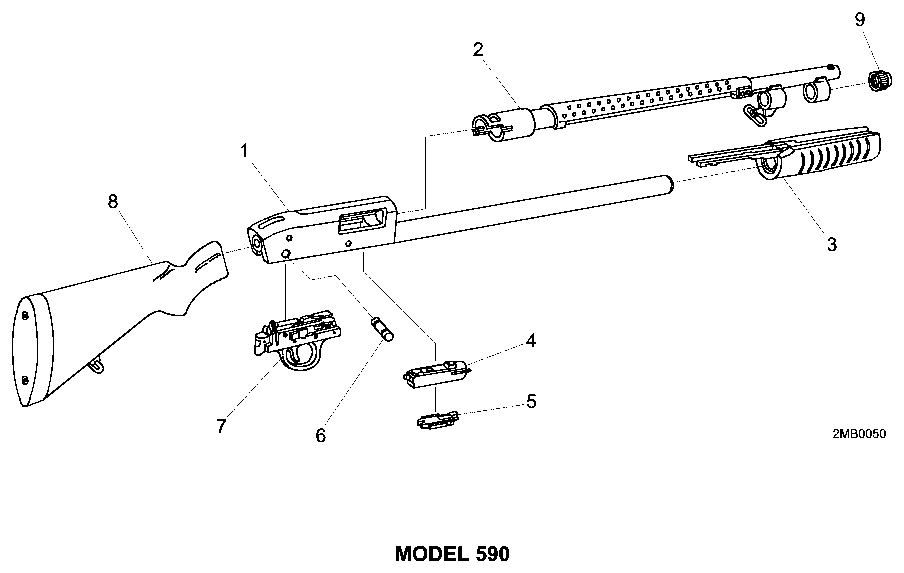
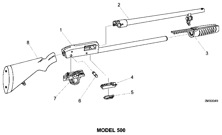
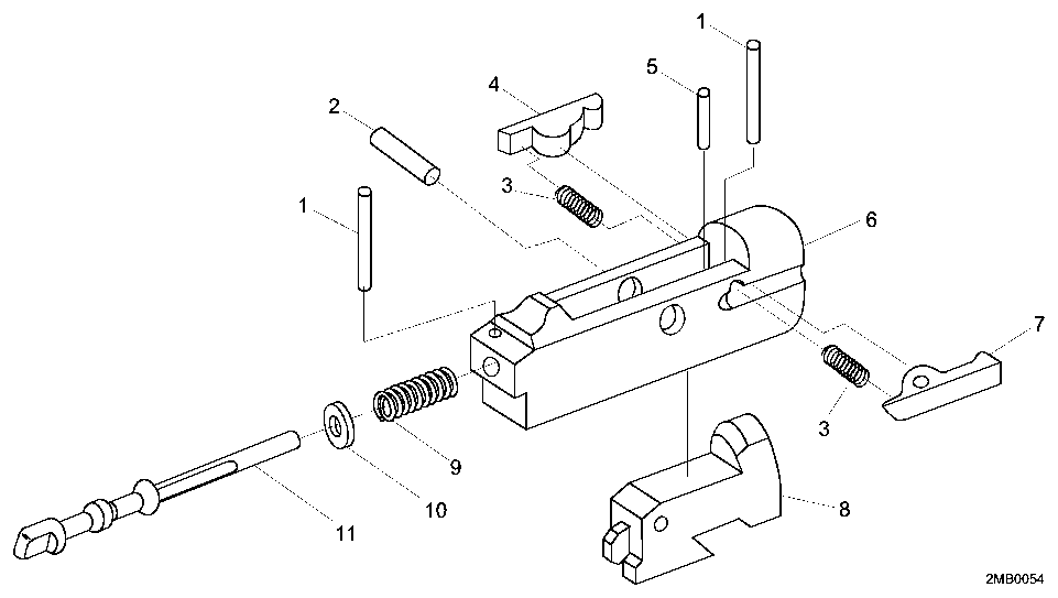
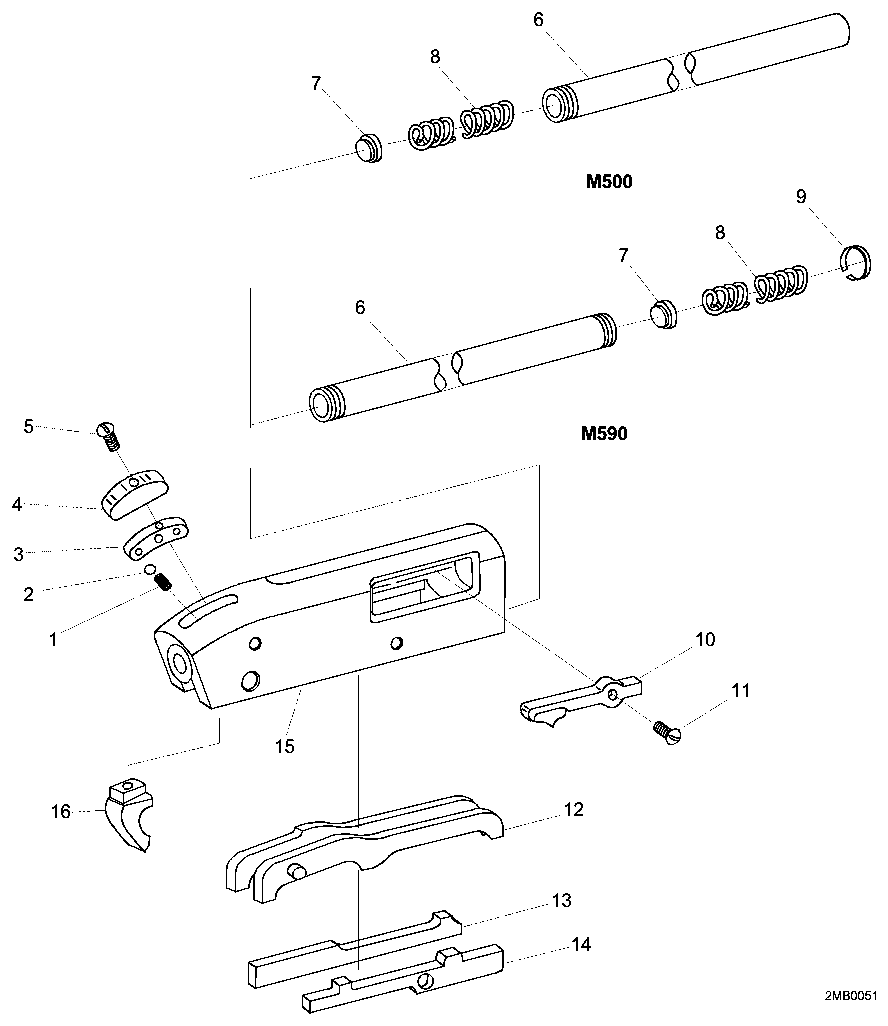
Torque specifications
| Fastener | Torque | Sequence, notes and the source's words | Where it comes from |
|---|---|---|---|
| Shell holder screws (3) Models with the stock-mounted shell holder |
12 in-lb 1.4 N·m · 1 ft-lb |
Engage the shell holder's three bosses in the matching recesses in the stock first; that aligns the screw holes. It fits either side of the stock. “Torque the screws to 12 in lbs (Figs. 31 and 32).” |
Owner's Manual for 500, 505, 510, 535, 590 and 835 Pump Action Shotguns — O.F. Mossberg & Sons, Inc., p. 25 resources.mossberg.com [1] |
Reported by other sources — not the manufacturer
| Fastener | Torque | Who says so, and their words | Where it comes from |
|---|---|---|---|
| Stock adaptor bolt (into rear of receiver) Mossberg 590 with Midwest Industries MI-SG-590 stock (replaces factory stock bolt) |
50 in-lb 5.6 N·m · 4.2 ft-lb |
Reported by Midwest Industries, Inc. Remove recoil pad and factory stock bolt; install grip adaptor into back of receiver (50 in-lb, Vibra-Tite); for Mossberg 590 attach grip with the 6 provided 8-32 flat heads (10 in-lb); fasten stock with four 10-24 flat heads (10 in-lb). Threadlocker: "Use the provided Vibra-tite on this bolt ONLY." “Install grip adaptor into back of the receiver. Use the provided Allen wrench and torque to 50inch lbs.” |
Mossberg 590 / Remington 970 Stock - MI-SG-590 / MI-SG-870 installation instructions — Midwest Industries, Inc., PDF p. 1 midwestindustriesinc.com [2] |
| Sling mount clamp screw (through sling mount halves, on extended magazine tube) Magpul Forward Sling Mount (MAG508) on a Mossberg 500/590 with an extended magazine tube |
max. 25 in-lb 2.8 N·m · 2.1 ft-lb |
Reported by Magpul Industries “Maximum Torque 25 in-lbs.” |
Magpul MAG508 Forward Sling Mount – Remington 870 & Mossberg 500/590 — Installation Instructions — Magpul Industries, PDF p. 1 (single page) magpul.com [4] |
| Sling mount clamp screw (through sling mount halves, on extended magazine tube) Magpul Forward Sling Mount (MAG508) on a Mossberg 500/590 with an extended magazine tube |
23 in-lb 2.6 N·m · 1.9 ft-lb |
Reported by Magpul Industries “For best operation and compatibility, torque to 23 in-lbs and place sling clamps within 2.25 inches of the end of the magazine tube or extension.” |
Magpul MAG508 Forward Sling Mount – Remington 870 & Mossberg 500/590 — Installation Instructions — Magpul Industries, PDF p. 1 (single page) magpul.com [4] |
| Grip-to-adaptor flat head screws (six 8-32) Midwest Industries shotgun stock on a Mossberg 590 (MI-SG-590; MI lists 'Mossberg 590 Shotguns') |
10 in-lb 1.1 N·m · 0.83 ft-lb |
Reported by Midwest Industries, Inc. “Slide the grip on the adaptor and attach with the provided flat heads. (For Remington 870 models you will use four 10-24 flat heads) (For Mossberg 590 models, you will use the 6 provided 8-32 flat heads. Torque these to 10inch lbs.” |
Mossberg 590 / Remington 970 Stock - MI-SG-590 / MI-SG-870 installation instructions — Midwest Industries, Inc., PDF p. 1 (single page) midwestindustriesinc.com [2] |
| Stock-to-grip 10-24 flat head screws (4) Midwest Industries shotgun stock on a Mossberg 590 (MI-SG-590; MI lists 'Mossberg 590 Shotguns') |
10 in-lb 1.1 N·m · 0.83 ft-lb |
Reported by Midwest Industries, Inc. “Slide the stock into the grip and fasten the four 10-24 flat heads. Torque to 10inch lbs.” |
Mossberg 590 / Remington 970 Stock - MI-SG-590 / MI-SG-870 installation instructions — Midwest Industries, Inc., PDF p. 1 (single page) midwestindustriesinc.com [2] |
| Stock adapter receiver screw (socket head bolt into rear of receiver) Mesa Tactical telescoping stock adapter (High-tube or LEO) on a Mossberg 500/590 |
20 ft-lb 27.1 N·m · 240 in-lb |
Reported by Mesa Tactical “Mossberg 500: 20 foot pounds” |
Mesa Tactical Telescoping Stock & Adapter Shotgun Conversion Kit — Assembly Guide (#47371 Rev II) — Mesa Tactical, PDF p. 10 of 16 mesatactical.com [5] |
| Pistol grip screw (1/4-28 pan head, grip to adapter) Mesa Tactical telescoping stock adapter kit on a Mossberg 500/590 |
10 ft-lb 13.6 N·m · 120 in-lb |
Reported by Mesa Tactical Threadlocker: None — 'Do not use Loctite on the pistol grip screw.' “If you have a torque wrench, tighten the fastener to 10 foot pounds.” |
Mesa Tactical Telescoping Stock & Adapter Shotgun Conversion Kit — Assembly Guide (#47371 Rev II) — Mesa Tactical, PDF p. 9 of 16 mesatactical.com [5] |
| LEO adapter double-ended flush cup cap screw Mesa Tactical LEO telescoping stock adapter for Mossberg 500 |
30 in-lb 3.4 N·m · 2.5 ft-lb |
Reported by Mesa Tactical “Use the small cap screw to secure the double-ended flush cup into the casting. If you have a torque wrench, tighten the fastener to 30 inch pounds.” |
Mesa Tactical Telescoping Stock & Adapter Shotgun Conversion Kit — Assembly Guide (#47371 Rev II) — Mesa Tactical, PDF p. 9 of 16 mesatactical.com [5] |
| Integrated-rail SureShell carrier: steel rail cleat to receiver (4 longer screws) and carrier to cleat (4 shorter screws) Mesa Tactical Integrated Rail SureShell shotshell carrier on a Mossberg 500/590 |
approx. 15 in-lb 1.7 N·m · 1.2 ft-lb |
Reported by Mesa Tactical Threadlocker: Blue Loctite on each screw “Mount the shell carrier and rail assembly to the cleat using the four shorter screws. Tighten all eight screws to about 15 inch-lbs and use a drop of blue Loctite® on each screw.” |
Mesa Tactical SureShell Shotshell Carriers — Assembly and Operation Guide (47374) — Mesa Tactical, PDF p. 15 of 20 mesatactical.com [6] |
| Banded front sight attachment nuts (5/16" nut driver) XS Sights banded front sight (winged ghost ring kit) on a Mossberg 500/590 standard (0.840-0.860") barrel |
30 in-lb 3.4 N·m · 2.5 ft-lb |
Reported by XS Sights Threadlocker: Red thread locking compound between band and barrel “If you are using a socket wrench, do not over tighten, doing so may break the attachment screw. The torque spec is only 30 inch pounds.” |
XS Sights Banded Shotgun Front Sight / Winged Ghost Ring — Installation Instructions — XS Sights, PDF p. 1 of 2 xssights.com [7] |
| Banded front sight attachment nuts (1/4" nut driver) XS Sights SHOTRAIL kit banded front sight on a Mossberg 500/590 standard barrel |
10 in-lb 1.1 N·m · 0.83 ft-lb |
Reported by XS Sights Threadlocker: Red thread locking compound between band and barrel “If you are using a socket wrench, do not over tighten, doing so may break the attachment screw. The torque spec is only 10 inch pounds.” |
XS Sights SHOTRAIL (Remington/Mossberg) with Banded Front Sight — Installation Instructions — XS Sights, PDF p. 2 of 2 xssights.com [8] |
Function check
- After any cleaning, disassembly, or accessory installation, check the shotgun for proper functioning before firing live ammunition.
- Move the safety button fully rearward to the ON position and keep the muzzle pointed in a safe direction.
- Open the action and visually and physically check the chamber, elevator, and magazine tube to be certain the shotgun is unloaded.
- Depress and hold the action lock lever, then open and close the action several times to check for free movement.
- Close the action, leave the safety ON, and pull the trigger fully rearward. The hammer should not fall.
- Remove your finger from the trigger and move the safety button to the OFF (fire) position. The hammer should not fall.
- With the safety OFF, pull the trigger. The hammer should fall.
- Load two dummy shells into the magazine and confirm they feed and eject cleanly, one per cycle.
- Confirm the takedown screw or magazine cap is tight.
Maintenance
Lubrication points
- Action bars in their receiver grooves
- Bolt body and locking lug
- Magazine tube exterior
- Hammer and sear pivots
Cleaning notes
The aluminum receiver on the 500 and 590 is not a bearing surface for the bolt in the way a steel receiver is — keep it clean and lightly lubricated, and avoid abrasive cleaning on the anodizing. Keep the inside of the magazine tube dry.
Suggested inspection interval: roughly every 1000 rounds. This is a general guideline, not a manufacturer specification.
Wear parts to inspect
Extractors (there are two on most models) · Cartridge stops · Magazine spring · Action bars · Bolt slide
Common issues
| Symptom | Likely cause | What to do |
|---|---|---|
| Action binds or will not close after reassembly | An action bar out of its groove, or the bolt slide installed incorrectly | Disassemble and reinstall, keeping both bars in their tracks. |
| Shells release from the magazine two at a time | Bent or worn cartridge stop | Replace the cartridge stop. see a gunsmith |
| Barrel loose after firing | Takedown screw or magazine cap backing off | Hand-tighten firmly before use and check it periodically. Some shooters use a witness mark to spot movement. |
Also covers
The procedures above are reported to apply to: Mossberg 500 · Mossberg 590 · Mossberg 590A1 · Mossberg 535 · Maverick 88 (similar, but the safety is in the trigger guard). Verify against the manual for your specific model.
Similar manual of arms
Legal notes
Sourcing
- Confidence
- high — Cross-checked against a primary source such as the manufacturer's manual or an issuing military technical manual.
- Verification
- Checked against the manufacturer manual
- Last updated
- 2026-10-29
References
Every source this page draws on, with its web address so you can read it yourself. Numbers in brackets elsewhere on the page point here.
- [1] Owner's Manual for 500, 505, 510, 535, 590 and 835 Pump Action Shotguns — O.F. Mossberg & Sons, Inc. manufacturer manual primary source
https://resources.mossberg.com/hubfs/manuals/12173-Owners-Manual-Pumps-English.pdf (checked 2026-09-14) - [2] Mossberg 590 / Remington 970 Stock - MI-SG-590 / MI-SG-870 installation instructions — Midwest Industries, Inc. manufacturer manual secondary source
https://midwestindustriesinc.com/content/installation-instructions/Mossberg-590-Remington-970-Stocks-Instructionrs.pdf (checked 2026-09-27) - [3] TM 9-1005-338-13&P: Technical Manual, Unit and Direct Support Maintenance (including Repair Parts and Special Tools List) for Mossberg 12-Gauge Shotgun, Model 500 (1005-01-295-1832) and Mossberg 12-Gauge Shotgun, Model 590 (1005-01-251-8578) — Headquarters, Department of the Army (2005) military technical manual primary source
https://archive.org/download/16-manuali-duso-e-manutenzione-per-armi-specifiche-use-and-maintenance-manuals-f_20230430/ARMY%20TM%209-1005-338-13%26P%20Technical%20Manual%20for%20Mossberg%2012-Gauge%20Shotgun%20Model%20500%2C%20590%20-%20May%202005.pdf (checked 2026-10-03) - [4] Magpul MAG508 Forward Sling Mount – Remington 870 & Mossberg 500/590 — Installation Instructions — Magpul Industries manufacturer manual secondary source
https://magpul.com/media/wysiwyg/Instructions/MAG508_SGA_Forward_Sling_Mount_Rem_Moss_INSRT.pdf (checked 2026-10-11) - [5] Mesa Tactical Telescoping Stock & Adapter Shotgun Conversion Kit — Assembly Guide (#47371 Rev II) — Mesa Tactical manufacturer manual secondary source
https://mesatactical.com/content/manuals/47371_Stock_Adapter_Manual_rev_ii.pdf (checked 2026-10-11) - [6] Mesa Tactical SureShell Shotshell Carriers — Assembly and Operation Guide (47374) — Mesa Tactical manufacturer manual secondary source
https://mesatactical.com/content/manuals/47374_SureShell_Shotshell_Carriers_Assembly_and_Operation_Guide.pdf (checked 2026-10-11) - [7] XS Sights Banded Shotgun Front Sight / Winged Ghost Ring — Installation Instructions — XS Sights manufacturer manual secondary source
https://xssights.com/content/Install%20Instructions/Banded%20Shotgun%20Winged%20Ghost%20Ring%20Instructions.pdf (checked 2026-10-11) - [8] XS Sights SHOTRAIL (Remington/Mossberg) with Banded Front Sight — Installation Instructions — XS Sights manufacturer manual secondary source
https://xssights.com/content/Install%20Instructions/SHOTRAIL%20Banded%20Front.pdf (checked 2026-10-11) - [9] Seeking help from someone who owns a Mossberg 500 in the Bay Area — Calguns.net community anecdotal source
https://www.calguns.net/forum/general-discussion/general-gun-discussions/910351-seeking-help-someone-own-mossberg-500-in-bay-area?p=21089362 (checked 2026-10-29) - [10] The Mossberg Model 500: History & Disassembly — American Rifleman (NRA) website secondary source
https://www.americanrifleman.org/content/the-mossberg-model-500-history-disassembly (checked 2026-10-29)
Notes: The disassembly, assembly, and function testing sections of the factory manual were read directly and this entry was corrected against them on 2026-09-14. Four corrections were made to the previous version: the bolt must be positioned mid-ejection-port before the barrel is removed; the barrel comes out with a rotational movement rather than a straight pull; the punch for the trigger housing pin is specified as no greater than 3/16 in; and the trigger housing is removed rear-portion-first. The reassembly order was also corrected — it is not the reverse of disassembly.