← All firearms · Printable work order
Remington Model 700
- easy
- Shop tier 1
- high confidence
- Rifle
- bolt action
- hunting
- precision
- recall history
field strip ~2 min · reassembly ~3 min · detail strip ~40 min
Specifications
- Manufacturer
- Remington Arms
- Origin
- United States
- Category
- Rifle
- Action
- Bolt action
- Calibers
- .308 Winchester, .30-06 Springfield, .223 Remington, 6.5 Creedmoor, 7mm Remington Magnum, .300 Winchester Magnum
- Capacity
- 3 to 5 rounds depending on caliber and magazine type
- Production
- 1962–present (in-production)
- Also known as
- 700 ADL, 700 BDL, 700 SPS, M24 / M40 (military derivatives)
Model-specific safety
- Remington issued a recall covering Model 700 and Model Seven rifles with the X-Mark Pro trigger manufactured between May 2006 and April 2014, and there has been extensive litigation regarding earlier Walker trigger designs and unintended discharges. If you own a Model 700 and do not know its trigger's recall status, check it with Remington before handling or firing it.
- Do not adjust the trigger yourself. Trigger adjustment on this rifle is a documented source of unintended discharges and is gunsmith work.
- Removing the barreled action from the stock changes the bedding relationship. Reinstall the action screws to a consistent torque or accuracy will shift.
- Clean from the breech with a bore guide. Cleaning a bolt rifle from the muzzle without one wears the crown and degrades accuracy permanently.
If it will not go back together
Common ways this firearm resists reassembly, and what is actually wrong. Forcing a part that will not seat is how firearms get damaged.
-
The bolt will not come out of the receiver.
Why The safety is not in the "S" position.
Fix Place the safety in "S", raise the bolt handle, pull it fully back, then push the bolt stop release in the trigger guard.
-
The bolt will not close after reinstalling it.
Why The integrated security system is still engaged. That is a separate mechanism from the safety.
Fix Disengage the security system — the red dot shows when it is off — then push the bolt handle down.
Under spring tension
- Firing pin spring inside the bolt (detail strip)
- Magazine follower spring
Easily lost parts
Bolt stop · Floorplate latch · Action screws
Tools
| Tool | Required | Used for | Substitute |
|---|---|---|---|
| Hex key or screwdriver matching the action screws | Optional | Removing the barreled action from the stock. Not needed for routine cleaning. | |
| Torque wrench | Optional | Reinstalling action screws to a consistent torque, which matters for accuracy. |
Shop difficulty
Shop tier 1 Tier 1 — easy among rifles and carbines, for the full job: strip to the parts that get coated and put it back together working. About 61 pieces, assembled with screws and pins. The one real trick is the bolt: the firing-pin assembly is taken apart under mainspring force using a coin and a small sleeve. The trigger housing comes out as a unit and is restricted, so there is nothing to time.
Parts: 44 numbered parts (Complete rifle (ADL and BDL grades mixed in one list; 60 line items, last key 49)), from Remington Model 700 Owner's Manual — RemArms LLC, p. 17–18 remarms.com [1].
Bench time: about 30 min to strip, 45 min to rebuild (estimate). Stock and bottom metal, bolt firing-pin assembly (coin and sleeve), ejector, bolt stop. The trigger housing is removed as a unit.
Small parts: 7 pins, 5 springs, 0 detents or plungers (counted from the manufacturer's parts list (one per key number unless a quantity is given))
What comes off for coating
- Stock / bottom metal: action screws, trigger guard / floorplate, magazine box, spring, follower, swivel studs, recoil pad or butt plate
- Bolt: firing pin assembly (shroud, cocking piece, mainspring), extractor, ejector and spring, firing pin cross pin
- Receiver: trigger assembly (as a unit), bolt stop and spring, safety (if receiver-mounted), scope bases / iron sights
Special tools
- coin or Remington bolt disassembly tool — Trapping the firing pin head
- 3/8 x 7/8 in sleeve with 3/16 in hole — Holding the mainspring while the cross pin is driven
- close-fitting drift punch — Firing pin cross pin, ejector pin
- torque driver — Action screws
Known pain points
- Taking the firing-pin assembly apart means compressing the mainspring and trapping it with a coin and a made-up sleeve before the cross pin can be driven out. The bolt plug comes off under spring force. (both)
Source: Exploded View: Remington Model 700 — American Rifleman (NRA) americanrifleman.org [21] — “Drive out firing pin cross pin (17) with close-fitting drift punch, and remove firing pin head. Unscrew bolt plug carefully as it is under force of mainspring (27).” - Reassembly needs a 3/8 in sleeve jig over the firing pin to hold the spring while the head and cross pin go back on. (reassembly)
Source: Exploded View: Remington Model 700 — American Rifleman (NRA) americanrifleman.org [21] — “When reassembling firing mechanism, place metal sleeve over front of firing pin, reassemble mainspring and bolt plug on firing pin, and screw bolt plug into bolt.” - The spring-loaded plunger ejector in the bolt face comes out with its pin and spring, and has to be held compressed when it goes back in. (both)
Source: Exploded View: Remington Model 700 — American Rifleman (NRA) americanrifleman.org [21] — “Drive out ejector pin (11), and remove ejector (10) and ejector spring (12) from front of bolt.”
See also 2 documented reassembly problems and their fixes.
Fit or check on rebuild
- Action screw torque — Front screw first, consistent torque.
- Trigger / safety function — The trigger assembly is restricted. Function-check it, don't adjust it.
- Integrated security system off — The bolt will not close with the ISS engaged.
- Re-zero sights or scope — Sights and optics come off for coating, and point of impact must be re-confirmed. This is a standard check, so no source.
This is Pew-Takedown's rating, not the manufacturer's. How tiers are rated. Forum reports are owners' experience, not specifications.
Procedures
Clear and Make Safe
Clear & Make Safe- Point the muzzle in a safe direction and keep your finger off the trigger.
- Place the safety in the on position.
- Lift the bolt handle and draw the bolt fully to the rear, extracting and ejecting any chambered round.
- Unload the magazine. On a hinged floorplate rifle, press the floorplate latch inside the front of the trigger guard and let the rounds fall out. On a detachable magazine rifle, remove the magazine. On a blind magazine, cycle the bolt to feed and eject each round.Removed at this step:
Magazine contents - Inspect the chamber and magazine well with a light and physically confirm the chamber is empty.
- Remove all live ammunition from the work area.
Field Strip — Bolt Removal
Field StripFor routine cleaning, this is all you need. The bore cleans from the breech with the bolt out.
- Complete the Clear and Make Safe procedure, and put on eye protection — the manual asks for it whenever you are disassembling or cleaning.
- Point the firearm in a safe direction and place the safety mechanism in the "S" position.TipS for safe. This is the opposite of what many bolt rifles want, and Remington states it for both removing and installing the bolt.
- Do not touch the trigger while moving the safety mechanism.WarningThe manual says never to pull the trigger with the safety in "S".
- Raise the bolt handle and pull it all the way back.
- Push the bolt stop release in the trigger guard, and slide the bolt assembly out of the firearm.Removed at this step:
Bolt assembly - Clean the bore from the breech using a bore guide, and clean the bolt face, lugs, and chamber.
- Stop here. The manual states that further disassembly is not recommended — the bedding is what the accuracy depends on.
Remove the Barreled Action from the Stock
Detail Strip tools requiredNeeded for a deep clean or for bedding work. Not part of routine maintenance.
- Verify the rifle is unloaded and remove the bolt.
- Remove the magazine or, on a hinged floorplate rifle, note the floorplate assembly's orientation before removing screws.
- Remove the front and rear action screws from the bottom of the stock.TipKeep track of which screw came from which hole; they are often different lengths.Removed at this step:
Action screwsFloorplate or magazine assembly - Lift the barreled action out of the stock.Removed at this step:
Stock - To reinstall, seat the action in the stock, start both screws by hand, then tighten the front screw first and the rear screw second, to a consistent torque.WarningInconsistent action screw torque is one of the most common causes of a rifle that will not hold zero. Many builders use 35 to 65 inch-pounds depending on the stock; consult your stock maker's specification.
Remove the firing pin assembly from the bolt
Detail Strip tools requiredUnscrews the complete firing pin assembly (firing pin, spring and bolt plug) from the bolt, using a coin or dog-tag in the firing pin head slot to hold the spring compressed. Operator level in the M24 manual (Chapter 3, para 3-6); the M24 deployment kit carries a spare firing pin assembly. The manual does not take the firing pin assembly itself apart.
Follows TM 9-1005-306-10 (Air Force TO 11W3-5-4-10-1): Operator's Manual, 7.62mm M24 Sniper Weapon System (SWS) (NSN 1005-01-240-2136), with Changes 1-8 [Distribution Statement C] — Headquarters, Department of the Army, para 3-6a, pp. 3-10.1 to 3-11 archive.org [11]
- Remove the bolt assembly from the rifle.TipPara 2-8: with the rifle cleared, push the bolt stop release up and slide the bolt out.
- Make sure the bolt is in the cocked position.TipThe manual's note: "Be sure bolt is in the cocked position."
- Hold the bolt vertically with the bolt handle at the top.
- Place the sear notch on the firing pin head against a hard surface and pull down on the bolt handle to compress the spring.
- Insert a thin object, such as an identification tag or a dime, into the slot in the firing pin head where it rises above the bolt plug.TipThe slot is only visible while the firing pin head is pushed above the bolt plug.
- Unscrew the firing pin assembly from the bolt assembly by turning it counterclockwise.Removed at this step:
Firing pin assembly - Place the firing pin into a 3/16 in hole drilled through a block of wood.TipThe wood block is the manual's fabricated item (Appendix E).
- Grasp the bolt plug and press it down to compress the spring until the object falls out of the slot.WarningThe bolt plug is under spring tension. Release it slowly to prevent injury.Removed at this step:
Coin or tag used as a keeper
Remove the magazine spring and follower from the floorplate
Detail Strip tools requiredUnclips the magazine spring and follower assembly from the hinged floorplate with the slotted tip of the cleaning rod, then separates the follower from the spring. Operator level (para 2-18).
Applies to: Rifles with a hinged floorplate, as on the M24
Follows TM 9-1005-306-10 (Air Force TO 11W3-5-4-10-1): Operator's Manual, 7.62mm M24 Sniper Weapon System (SWS) (NSN 1005-01-240-2136), with Changes 1-8 [Distribution Statement C] — Headquarters, Department of the Army, para 2-18, p. 2-17 archive.org [11]
- Push the floorplate latch to release the floorplate.
- Open the floorplate fully.
- Insert the slotted tip of the cleaning rod between the spring leaf and the floorplate it is attached to.
- Lift the magazine spring and follower assembly and pull it toward the rear of the floorplate to free it.Removed at this step:
Magazine spring and follower assembly - Separate the magazine spring from the magazine follower.Removed at this step:
Magazine springMagazine follower
Remove the day optic sight
Detail Strip tools requiredLoosens the two mounting ring nuts and rotates the M24 day optic sight off its base. Operator level (para 2-14).
Applies to: M24 SWS day optic sight in its issue rings
Follows TM 9-1005-306-10 (Air Force TO 11W3-5-4-10-1): Operator's Manual, 7.62mm M24 Sniper Weapon System (SWS) (NSN 1005-01-240-2136), with Changes 1-8 [Distribution Statement C] — Headquarters, Department of the Army, para 2-14, p. 2-11 archive.org [11]
- Loosen the front mounting ring nut counterclockwise with the 1/2 in combination wrench.
- Loosen the rear mounting ring nut counterclockwise with the 1/2 in combination wrench.
- Rotate the day optic sight toward the nuts.
- Lift the day optic sight off the base.Removed at this step:
Day optic sight with rings
Install the firing pin assembly in the bolt
Detail Reassembly tools requiredScrews the firing pin assembly back into the bolt and re-cocks it by turning the bolt plug until the firing pin head drops into the small notch on the rear of the bolt. Operator level (para 3-6b). The bolt must be cocked before it will go back into the rifle (para 2-9 note).
Follows TM 9-1005-306-10 (Air Force TO 11W3-5-4-10-1): Operator's Manual, 7.62mm M24 Sniper Weapon System (SWS) (NSN 1005-01-240-2136), with Changes 1-8 [Distribution Statement C] — Headquarters, Department of the Army, para 3-6b, pp. 3-11 to 3-12 archive.org [11]
- Hold the firing pin assembly vertically with the bolt plug at the top.
- Insert the firing pin into the 3/16 in hole drilled in the block of wood.
- Grasp the bolt plug and press it down to compress the spring.WarningThe bolt plug is under spring tension. Release it slowly to prevent injury.
- While the firing pin head is pushed above the bolt plug, place an object such as an identification tag or a dime into the slot in the firing pin head.
- Screw the firing pin assembly into the bolt assembly by turning it clockwise.
- Place the sear notch against a hard surface and pull down on the bolt handle to remove the object from the slot.
- Turn the bolt plug until the firing pin head drops into the small notch on the rear rim of the bolt.TipThe bolt is now cocked, which it must be before it is reinstalled (Figure 3-9 shows the cocked position).
Assemble the magazine spring and follower to the floorplate
Detail ReassemblyFits the long leg of the magazine spring under the follower tabs and the short leg under the floorplate tabs. Operator level (para 2-19).
Applies to: Rifles with a hinged floorplate, as on the M24
Follows TM 9-1005-306-10 (Air Force TO 11W3-5-4-10-1): Operator's Manual, 7.62mm M24 Sniper Weapon System (SWS) (NSN 1005-01-240-2136), with Changes 1-8 [Distribution Statement C] — Headquarters, Department of the Army, para 2-19, pp. 2-17 to 2-18 archive.org [11]
- Compress the magazine spring to find its longest leg.
- Insert the longest spring leg under the tabs on the magazine follower and slide it forward until it snaps into position.TipMake sure the leg is seated under the follower tabs.
- Align the short spring leg with the tabs on the floorplate.
- Slide the magazine spring and follower assembly into the floorplate until it snaps into position.
Mount the day optic sight
Detail Reassembly tools requiredMounts the day optic sight and rings on the base in the same slots every time, then torques the rear and front ring nuts to 65 in-lb with the T-handle torque wrench and re-torques after the first 10 rounds. Operator level (para 2-13).
Applies to: M24 SWS day optic sight in its issue rings
Follows TM 9-1005-306-10 (Air Force TO 11W3-5-4-10-1): Operator's Manual, 7.62mm M24 Sniper Weapon System (SWS) (NSN 1005-01-240-2136), with Changes 1-8 [Distribution Statement C] — Headquarters, Department of the Army, para 2-13, pp. 2-9 to 2-11 archive.org [11]
- Lubricate the threads of each mounting nut.WarningMake sure the mounting base is fastened securely to the rifle. A loose mounting may let the sight and base mount come off the rifle when firing and injure the shooter.
- Check that each mounting nut and mount claw moves smoothly.
- Inspect between each mounting ring nut and mount claw for burrs and foreign matter, and remove any you find.
- Check that the mounting surface of the base is free of dirt, oil and grease.
- Set the day optic sight and rings on the base, with each ring bolt spline in the selected set of slots.TipThere are two sets of mounting slots. Pick the set that gives proper eye relief and always use that same set, so the system keeps its zero.
- Slide the rear mount claw against the base and finger-tighten its mounting ring nut.
- Slide the front mount claw against the base and finger-tighten its mounting ring nut.
- Tighten the rear mounting ring nut with the T-handle torque wrench preset to 65 in-lb.WarningBe sure the T-handle torque wrench has been certified/calibrated in accordance with TB 43-0196.TipThe manual's alternative, a 1/4 turn (90 degrees) with the 1/2 in combination wrench on the rear then the front nut, is only for a sight that has been attached and reattached more than 50 times and can no longer be re-zeroed by live firing.
- Tighten the front mounting ring nut with the T-handle torque wrench.
- After the first 10 rounds have been fired, re-torque the rear mounting ring nut and then the front.
Reassembly
Reassembly- Point the firearm in a safe direction and place the safety mechanism in the "S" position.
- Align the lugs on the bolt assembly with the receiver.
- Slide the bolt assembly into the receiver and push it all the way in.
- Push the bolt handle down to close the bolt.TipIf the bolt will not close, the integrated security system is still engaged. It has to be disengaged for the bolt to close, and the red dot will show when it is. That is a separate mechanism from the safety.
- Cycle the bolt several times to confirm smooth travel and correct cocking, and confirm the bolt stop retains it when the action is opened fully.
- Perform the function check.
Patent drawings
not under copyrightDrawings from US patents on this design. A patent shows the invention as the inventor filed it; the firearm that shipped can differ in detail, and later production often does. Use them to see how the parts relate, not as a parts reference or a procedure. Per the USPTO, the text and drawings of a patent are typically not subject to copyright; each patent here was checked for a copyright notice.
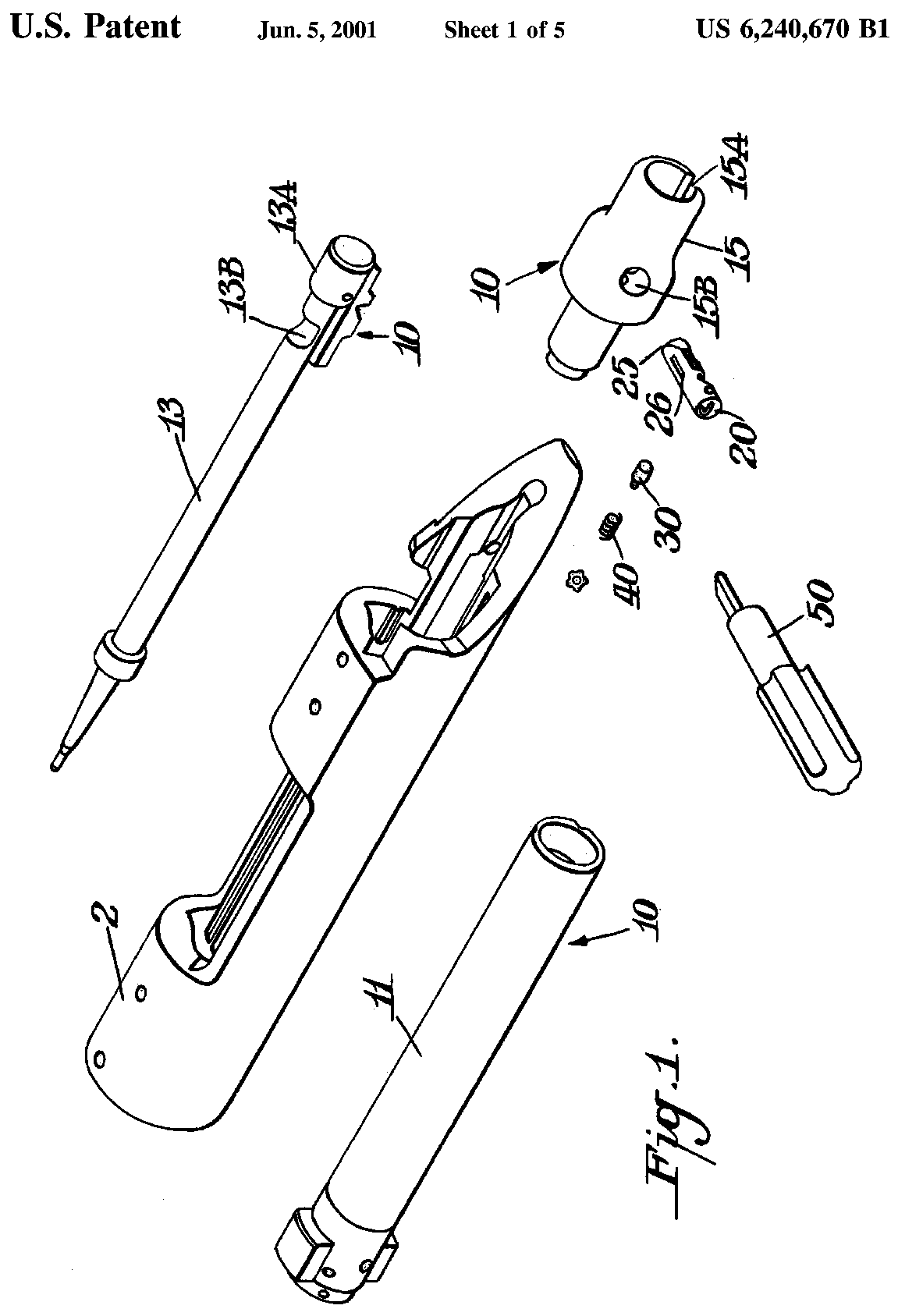
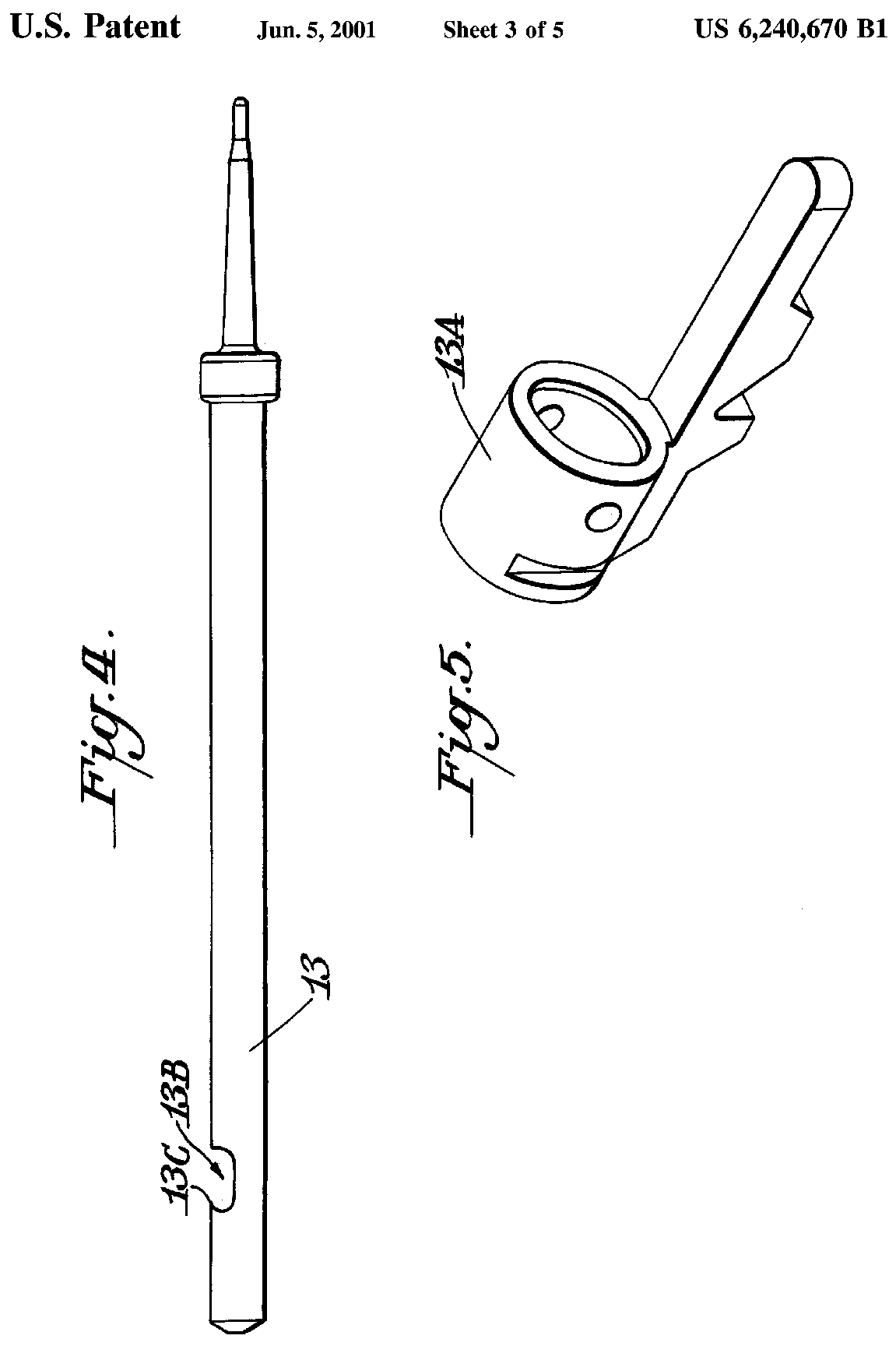
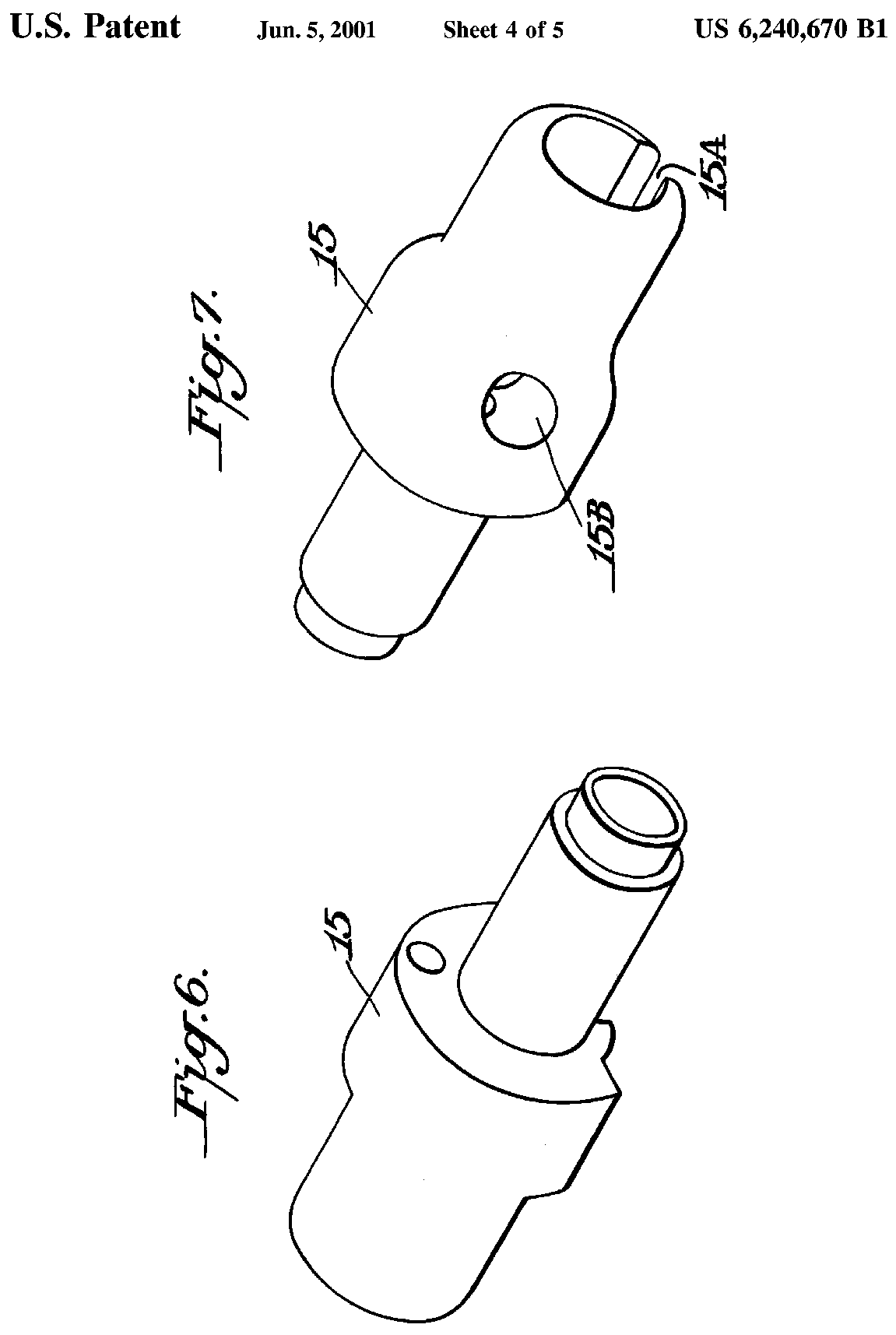
US Patent 6,240,670 — Locking mechanism for firearms
David S. Findlay · assigned to RA Brands, L.L.C. · filed 1999-09-03 · granted 2001-06-05. Full patent (USPTO)
The Remington Integrated Security System (ISS) key lock in the bolt plug of the Model 700 bolt, with an exploded view of the receiver and bolt assembly (bolt body, firing pin, firing pin head, bolt plug).
Why this is the Remington Model 700’s patent: named by a historical source — Integrated Security System (ISS) | State of California - Department of Justice - Office of the Attorney General — California Department of Justice, Bureau of Firearms oag.ca.gov [20]: “Manufacturer states that Remington Model 700 and Model Seven centerfire rifles equipped with the Remington Integrated Security System (ISS), patent number 6,240,670B1, function properly without an additional firearms safety device.”
Torque specifications
| Fastener | Torque | Sequence, notes and the source's words | Where it comes from |
|---|---|---|---|
| Trigger guard screws (front and rear guard/action screws) M24 SWS (Remington 700 long action in the M24 stock) |
65 in-lb 7.3 N·m · 5.4 ft-lb |
Checked before and after firing as part of operator inspection; the stock-removal page (para 3-4, p. 3-6, PDF p. 89, image only) also says both screws must be tightened to 65 in. lbs. with the T-handle torque wrench. “Check guard screws for proper torque of 65 in. lbs. using T-handle torque wrench” |
TM 9-1005-306-10 (Air Force TO 11W3-5-4-10-1): Operator's Manual, 7.62mm M24 Sniper Weapon System (SWS) (NSN 1005-01-240-2136), with Changes 1-8 [Distribution Statement C] — Headquarters, Department of the Army, para 2-17b, p. 2-16 archive.org [11] |
| Day optic sight mounting ring nuts (rear, then front) M24 SWS day optic sight rings only |
65 in-lb 7.3 N·m · 5.4 ft-lb |
Rear ring nut first, then front; re-torque rear then front after the first 10 rounds (para 2-13l). “Using the T-handle torque wrench. which is preset to 65 in. lb., tighten the rear mounting ring nut.” |
TM 9-1005-306-10 (Air Force TO 11W3-5-4-10-1): Operator's Manual, 7.62mm M24 Sniper Weapon System (SWS) (NSN 1005-01-240-2136), with Changes 1-8 [Distribution Statement C] — Headquarters, Department of the Army, para 2-13j, p. 2-10 archive.org [11] |
Notes: The manufacturer's documents give no torque value. They say: "Replace and tighten the trigger guard (stock) screws." (Owner's Manual, Model 700 (RD7055 F3509 REV 0926), PDF p. 15)
Reported by other sources — not the manufacturer
| Fastener | Torque | Who says so, and their words | Where it comes from |
|---|---|---|---|
| Action screws (front and rear) Remington 700 short action in a Magpul Hunter 700 stock (aluminium bedding block) |
55–60 in-lb 6.2–6.8 N·m · 4.6–5 ft-lb |
Reported by Magpul Industries Install the trigger guard into the stock (with the Trigger Guard Spacer if reinstalling the factory Remington trigger guard), install the action screws, tighten both front and rear. “Install the action screws. Tighten both the front and rear action screws to 55-60 inch pounds.” |
Hunter 700 Stock (MAG495) Installation Instructions — Magpul Industries, PDF p. 1 magpul.com [2] |
| Action screws (front and rear) Remington 700 long action in a Magpul Hunter 700L stock |
55–60 in-lb 6.2–6.8 N·m · 4.6–5 ft-lb |
Reported by Magpul Industries “Install the action screws. Tighten both the front and rear action screws to 55-60 inch pounds.” |
Hunter 700L Stock (MAG483) Installation Instructions — Magpul Industries, PDF p. 1 magpul.com [3] |
| Action screws (front and rear) Remington 700 short action in a Magpul Hunter Lite stock (MAG1422) |
55–60 in-lb 6.2–6.8 N·m · 4.6–5 ft-lb |
Reported by Magpul Industries Place the barreled action into the Bedding Block with the rear of the recoil lug against the rear of the Recoil Lug Slot, hand-tighten both action screws, then torque. Source adds: 'NOTE: Refer to the rifle manufacturer’s instructions for torque specifications.' “Using a torque wrench, tighten the front and rear Action Screws to 55-60 in-lbs.” |
Hunter Lite Stock – Remington 700 Short Action (MAG1422) Installation Instructions, 092-0107-B — Magpul Industries, PDF p. 1 magpul.com [4] |
| Action screws (front and rear) Remington 700 short and long action (and Remington 700-footprint actions) in a Magpul Pro 700 / Pro 700L chassis |
55–60 in-lb 6.2–6.8 N·m · 4.6–5 ft-lb |
Reported by Magpul Industries Pull the barreled action back, ensuring the recoil lug is making contact against the rear surface of the Recoil Lug Slot, and tighten both the front and rear Action Screws. “Using a torque wrench, tighten the front and rear Action Screws to 55-60 in-lbs.” |
Pro 700 & Pro 700L Rifle Chassis Instructions — Magpul Industries, PDF p. 7 magpul.com [5] |
| Action screws (front and rear) Remington 700 SA/LA in a KRG Bravo Chassis (Gen 2) |
65 in-lb 7.3 N·m · 5.4 ft-lb |
Reported by Kinetic Research Group (KRG) Finger-tighten the front screw, pull the action rearward to seat against the recoil lug, keep the action level; tighten front then rear a little at a time, switching back and forth, then torque both incrementally. “Torque both screws to 65 in-lbs of torque in an incremental manner, moving back and forth between the two screws until full torque is reached.” |
KRG Bravo Chassis (Gen 2) Installation Instructions (INST-BRV) — Kinetic Research Group (KRG), PDF p. 2 kineticresearchgroup.com [6] |
| Takedown (action) screws Remington 700 and comparable factory rifles in a Stocky's solid wood stock |
25–30 in-lb 2.8–3.4 N·m · 2.1–2.5 ft-lb |
Reported by Stocky's Stocks Tighten the front screw last, this puts any residual stress to the rear, away from the locking lugs. “Torque Values: Solid wood - 25-30 in/lbs; Laminates 25-40 in/lbs; Fiberglass 30-40 in/lbs; Aluminum - 50-60 in/lbs - Tighten the front screw last, this puts any residual stress to the rear, away from the locking lugs.” |
Upgrading Your Factory Stock With A New Riflestock At Stocky's - Rem 700 and Comparable Factory Rifles — Stocky's Stocks stockysstocks.com [7] |
| Takedown (action) screws Remington 700 and comparable factory rifles in a Stocky's fiberglass stock |
30–40 in-lb 3.4–4.5 N·m · 2.5–3.3 ft-lb |
Reported by Stocky's Stocks Tighten the front screw last, this puts any residual stress to the rear, away from the locking lugs. “Fiberglass 30-40 in/lbs” |
Upgrading Your Factory Stock With A New Riflestock At Stocky's - Rem 700 and Comparable Factory Rifles — Stocky's Stocks stockysstocks.com [7] |
| Takedown (action) screws Remington 700 and comparable factory rifles in a Stocky's aluminum-bedded stock |
50–60 in-lb 5.6–6.8 N·m · 4.2–5 ft-lb |
Reported by Stocky's Stocks Tighten the front screw last, this puts any residual stress to the rear, away from the locking lugs. “Aluminum - 50-60 in/lbs” |
Upgrading Your Factory Stock With A New Riflestock At Stocky's - Rem 700 and Comparable Factory Rifles — Stocky's Stocks stockysstocks.com [7] |
| Front action screw Remington 700 (three-screw listing) |
55–60 in-lb 6.2–6.8 N·m · 4.6–5 ft-lb |
Reported by Fix It Sticks (compiled reference list) “Front action screw: 55-60 in-lbs” |
Torque Specs (Torque Specs by Brand — Remington 700) — Fix It Sticks (compiled reference list) store.fixitsticks.com [8] |
| Middle action screw Remington 700 (three-screw listing) |
40–45 in-lb 4.5–5.1 N·m · 3.3–3.7 ft-lb |
Reported by Fix It Sticks (compiled reference list) “Middle action screw: 40-45 in-lbs” |
Torque Specs (Torque Specs by Brand — Remington 700) — Fix It Sticks (compiled reference list) store.fixitsticks.com [8] |
| Rear action screw Remington 700 (three-screw listing) |
15–20 in-lb 1.7–2.3 N·m · 1.2–1.7 ft-lb |
Reported by Fix It Sticks (compiled reference list) “Rear action screw: 15-20 in-lbs” |
Torque Specs (Torque Specs by Brand — Remington 700) — Fix It Sticks (compiled reference list) store.fixitsticks.com [8] |
| Action screws — front / rear Remington-size screws/actions in Manners stocks (front value) |
65 in-lb 7.3 N·m · 5.4 ft-lb |
Reported by Fix It Sticks (compiled reference list) “Action Screws: 65 in-lbs Front / 45 in-lbs Rear” |
Torque Specs (Torque Specs by Brand — Remington 700) — Fix It Sticks (compiled reference list) store.fixitsticks.com [8] |
| Rear action screw Remington-size screws/actions in Manners stocks |
45 in-lb 5.1 N·m · 3.7 ft-lb |
Reported by Fix It Sticks (compiled reference list) “Action Screws: 65 in-lbs Front / 45 in-lbs Rear” |
Torque Specs (Torque Specs by Brand — Remington 700) — Fix It Sticks (compiled reference list) store.fixitsticks.com [8] |
| Action screws Remington 700 in a J Allen Enterprises JAE 700 / 700 XL stock |
65 in-lb 7.3 N·m · 5.4 ft-lb |
Reported by Fix It Sticks (compiled reference list) “Action Screws: 65 in-lbs” |
Torque Specs (Torque Specs by Brand — Remington 700) — Fix It Sticks (compiled reference list) store.fixitsticks.com [8] |
| Action screws (front and rear) Remington 700 SA/LA in an MDT Oryx chassis |
60–65 in-lb 6.8–7.3 N·m · 5–5.4 ft-lb |
Reported by MDT Sporting Goods Ltd. (Modular Driven Technologies, MDT) Push the action rearward against the recoil lug and torque the front action screw first, then the rear (manual p. 1: 'first torquing the front then the rear action screw'). “Remington 700 SA/LA — 3/16” Hex Wrench — 60-65 inch-pounds” |
MDT Oryx Chassis System — User Manual (13694, Version 07.14.26), attached to MDT help-centre article 'ORYX Chassis Installation Guides' — MDT Sporting Goods Ltd. (Modular Driven Technologies, MDT), PDF p. 2 (inlet-specific torque table) support.mdttac.com [12] |
| Action screws (front and rear) Remington 700 (stock OEM actions) in an MDT TAC21 Gen 2 chassis |
60 in-lb 6.8 N·m · 5 ft-lb |
Reported by MDT Sporting Goods Ltd. (Modular Driven Technologies, MDT) Start with the front screw. Forend bolts (chassis hardware) max 36 in-lb. “15. Torque the action screws to 60 inch pounds starting with the front screw.” |
MDT TAC21 Gen 2 Chassis System — Owner's Manual (Tac21_Manual.pdf, 2020), attached to MDT help-centre article 'TAC 21 installation manual' — MDT Sporting Goods Ltd. (Modular Driven Technologies, MDT), PDF p. 7 ('TAC21 Gen 2 Chassis System Fo support.mdttac.com [13] |
| Action screws (front and rear) Remington 700 short action (and clones) in an MDT/JAE JAE-700 G4 chassis |
65 in-lb 7.3 N·m · 5.4 ft-lb |
Reported by MDT Sporting Goods Ltd. (Modular Driven Technologies, MDT) Seat the action rearward, snug both, then torque the FRONT screw first, then the REAR. Re-torque after ~100 rounds. “Next, using a torque wrench, torque the FRONT action screw [1], then the REAR action screw [2] to 65 inch/lbs.” |
JAE-700 G4 Chassis System — Owner's Manual 'For REM700 / Clones Short Action' (now an MDT product), attached to MDT help-centre article 'JAE G4 installation manual' — MDT Sporting Goods Ltd. (Modular Driven Technologies, MDT), PDF p. 5 support.mdttac.com [14] |
| Action screws (front and rear) Remington 700 in a KRG X-Ray chassis (earlier generation — 'X-Ray Chassis Gen 2' instructions) |
35–50 in-lb 4–5.6 N·m · 2.9–4.2 ft-lb |
Reported by Kinetic Research Group (KRG) Start the front screw, then the rear; seat the action rearward against the recoil lug; tighten alternately front/rear in small increments to the final value. KRG adds: some rifles shoot better around 40 in-lb. “Step 8: Torque both screws to 35-50 in-lbs of torque in an incremental manner, moving back and forth between the two screws until full torque is reached.” |
KRG X-Ray Chassis — Installation Instructions ('Download Instructions X-Ray Chassis Gen 2' on the KRG X-Ray product page) — Kinetic Research Group (KRG), PDF p. 2 kineticresearchgroup.com [15] |
| Chassis screw just behind the action Remington 700 long action in a KRG Bravo chassis (Long Action Gen 1 instructions) |
approx. 45 in-lb 5.1 N·m · 3.7 ft-lb |
Reported by Kinetic Research Group (KRG) Tighten only AFTER the action screws are fully torqued (65 in-lb); the screw ships finger tight. “Step 6: Tighten the screw just behind the action to about 45 in-lbs AFTER the action screws are fully torque.” |
KRG Bravo Chassis for Rem 700 LA — Installation Instructions (Long Action Gen 1) — Kinetic Research Group (KRG), PDF p. 2 kineticresearchgroup.com [16] |
| Action screws (guard screws) Remington 700 in an H-S Precision Pro-Series stock |
65 in-lb 7.3 N·m · 5.4 ft-lb |
Reported by H-S Precision, Inc. H-S Precision FAQ: front screw first, rear screw second. “Torque the screws to 65 in/lbs.” |
H-S Precision — Instructions for the Remington 700 Pro-Series® Stocks — H-S Precision, Inc., PDF p. 1, step 3 hsprecision.com [17] |
| Action screws (barreled action to UMC) Remington 700 and R700-pattern actions in a Grayboe stock with Universal Mini Chassis (UMC) |
45 in-lb 5.1 N·m · 3.7 ft-lb |
Reported by Grayboe Install the UMC into the stock first (UMC-to-stock screws 60 in-lb), then the barreled action. “Set the barreled action into the mini chassis. Install the two supplied action screws (same length front and rear). Torque both screws to 45 inch-pounds.” |
Grayboe — UMC (Universal Mini Chassis) Installation Instructions (web page) — Grayboe, p. Section 'Remington 700 & Clones', Step 3 grayboe.com [18] |
| Action screws (front and rear) Remington (700-footprint) action in a MasterPiece Arms BA chassis |
65 in-lb 7.3 N·m · 5.4 ft-lb |
Reported by MasterPiece Arms, Inc. Snug front then rear; torque front to 25 in-lb, then rear to 25 in-lb; then front to 65 in-lb, then rear to 65 in-lb. Always start with the front screw. Re-check at 100-125 rounds and again after 500. “9. Using an inch lb torque wrench, torque the front action screw to 25 inch lbs. Then do the same for the rear screw. 10. Then go back to the front action screw and torque to the final spec of 65 inch lbs. Then return to the rear and do the same.” |
MasterPiece Arms BA Chassis System — Installation, Setup and Usage (rev B) — MasterPiece Arms, Inc., PDF p. 1–2, steps 9–10 masterpiecearms.com [19] |
Materials and factory finish
As stated by Remington Arms. Prep, masking and cure depend on these; a polymer or aluminium part, a nitrided or anodised finish, and a blued steel part are each a different job. Variants with other finishes may exist — check the maker's page for the exact SKU on the bench.
| Component | Material | Factory finish | Where it comes from |
|---|---|---|---|
| Receiver | steel | — | The Model 700 — 700 Series — Remington Arms (remington-arms.com, Frontier Defense Group, LLC) remington-arms.com [10] “SOLID-STEEL RECEIVER Machined from solid-steel bar stock for unrivaled uniformity and strength.” |
Parts list
Transcribed from the manufacturer's parts list (Remington Model 700 Owner's Manual — RemArms LLC, p. 17–18 remarms.com [1]) — Model 700 'Parts List' (ADL and BDL grades mixed in one list) from the combined Model 700 / Seven / 673 manual. Omitted: the separate Model Seven (pp.19–20) and Model 673 (pp.21–22) lists.. Key numbers refer to the exploded view in that document.
60 parts
| Key | Part | Part no. | Qty | Group |
|---|---|---|---|---|
| 1 | Barrel Assembly | 1 | ||
| 2 | Bolt Assembly | 1 | ||
| 3 | Bolt Plug | 1 | ||
| 4 | Bolt Stop (Restricted) | 1 | ||
| 5 | Bolt Stop Pin (Restricted) | 1 | ||
| 6 | Bolt Stop Spring (Restricted) | 1 | ||
| 7 | Butt Plate | 1 | ||
| Butt Plate Frame (New Style Not Shown) | 1 | |||
| Butt Plate Insert (New Style Not Shown) | 1 | |||
| Butt Plate Frame Screw (New Style) | 1 | |||
| 8 | Butt Plate Spacer | 1 | ||
| 9 | Butt Plate Screw | 1 | ||
| 10 | Center Guard Screw ADL Grade | 1 | ||
| 11 | Ejector | 1 | ||
| 12 | Ejector Pin | 1 | ||
| 13 | Ejector Spring | 1 | ||
| 14 | Extractor | 1 | ||
| 16 | Firing Pin Assembly | 1 | ||
| 17 | Firing Pin Cross Pin | 1 | ||
| 18 | Floor Plate Latch, BDL Grade | 1 | ||
| 19 | Floor Plate Latch Pin, BDL Grade | 1 | ||
| 20 | Floor Plate Latch Spring, BDL Grade | 1 | ||
| 21 | Floor Plate Pivot Pin, BDL Grade | 1 | ||
| 22 | Front Guard Screw | 1 | ||
| 23 | Front Guard Screw Bushing, ADL Grade | 1 | ||
| 24 | Front Sight | 1 | ||
| Front Sight (Low) | 1 | |||
| 25 | Front Sight Ramp BDL | 1 | ||
| 26 | Front Sight Ramp Screw | 1 | ||
| 27 | Front Sight Hood | 1 | ||
| 29 | Front Swivel Screw | 1 | ||
| Grip Cap, BDL Grade (Not Shown) | 1 | |||
| Grip Cap Screw | 1 | |||
| Grip Cap Spacer (Not Shown) | 1 | |||
| 30 | Magazine, ADL Grade | 1 | ||
| Magazine, BDL Grade (Not Shown) | 1 | |||
| 31 | Magazine Follower, ADL – Short Action | 1 | ||
| Magazine Follower, BDL | 1 | |||
| Magazine Tab Screw, ADL Grade | 1 | |||
| 32 | Magazine Spring, ADL Grade | 1 | ||
| Magazine Spring, BDL Grade | 1 | |||
| 33 | Main Spring | 1 | ||
| 34 | Rear Guard Screw | 1 | ||
| 35 | Rear Sight Aperture | 1 | ||
| Rear Sight Assembly | 1 | |||
| Rear Sight Base | 1 | |||
| 37 | Rear Sight Base Screw (2) | 2 | ||
| 38 | Rear Sight Slide | 1 | ||
| 39 | Elevation Screw | 1 | ||
| 40 | Rear Swivel Screw | 1 | ||
| 41 | Receiver Plug Screw | 1 | ||
| 42 | Sear Pin (Restricted) | 1 | ||
| 44 | Stock Assembly, ADL Grade | 1 | ||
| Stock Assembly, BDL Grade | 1 | |||
| Stock Reinforcing Screw (Not Shown) | 1 | |||
| Stock Reinforcing Screw Dowel (Not Shown) | 1 | |||
| 46 | Trigger Assembly (Restricted) | 1 | ||
| 47 | Trigger Guard | 1 | ||
| 48 | Trigger Guard Assembly, BDL Grade | 1 | ||
| 49 | Windage Screw | 1 |
Function check
- Verify the rifle is unloaded and the magazine is empty before each check.
- Cycle the bolt and confirm it cocks on opening and closes fully into battery.
- With the action cocked, engage the safety and press the trigger. The firing pin must not release.
- Disengage the safety without touching the trigger. The firing pin must not release.
- Press the trigger and confirm the firing pin releases cleanly.
- Confirm the bolt stop retains the bolt.
- Load dummy rounds and confirm they feed from the magazine and eject cleanly.
- If the rifle ever discharges when the safety is disengaged or the bolt is closed, stop using it immediately and have it inspected.
Maintenance
Lubrication points
- Bolt lugs and the locking recesses
- Bolt body where it rides in the raceway
- Cocking cam surfaces
- Extractor
Cleaning notes
Clean from the breech with a bore guide. Do not over-lubricate the firing pin assembly — oil there thickens in cold weather and causes light strikes. Keep the chamber dry and free of oil before shooting; oil in a chamber raises bolt thrust.
Suggested inspection interval: roughly every 500 rounds. This is a general guideline, not a manufacturer specification.
Wear parts to inspect
Extractor (the riveted extractor is a known wear point) · Ejector plunger and spring · Bolt lugs · Firing pin spring
Common issues
| Symptom | Likely cause | What to do |
|---|---|---|
| Light strikes or misfires in cold weather | Heavy or congealed oil in the firing pin assembly | Disassemble the bolt, degrease the firing pin assembly, and reassemble dry or with a light synthetic lubricant. |
| Group size opens up after cleaning or transport | Action screw torque changed | Retorque the action screws consistently, front first. |
| Failure to extract | Worn riveted extractor or a fouled chamber | Clean the chamber. If it persists, the extractor is a known upgrade point. see a gunsmith |
| Rifle discharges when the safety is released or the bolt is closed | Trigger mechanism fault | Stop using the rifle immediately, unload it, and have the trigger inspected. Check the rifle's recall status with the manufacturer. see a gunsmith |
Also covers
The procedures above are reported to apply to: Remington Model Seven · Remington 700 in all configurations · M24 and M40 military derivatives (with differences). Verify against the manual for your specific model.
Similar manual of arms
Sourcing
- Confidence
- high — Cross-checked against a primary source such as the manufacturer's manual or an issuing military technical manual.
- Verification
- Checked against the manufacturer manual
- Last updated
- 2026-10-29
References
Every source this page draws on, with its web address so you can read it yourself. Numbers in brackets elsewhere on the page point here.
- [1] Remington Model 700 Owner's Manual — RemArms LLC manufacturer manual primary source
https://www.remarms.com/sites/default/files/2026%20Revised%20OMs/700%20Manual%20RD7055%20Final%20F3509%20(REV%200526).pdf (checked 2026-09-15) - [2] Hunter 700 Stock (MAG495) Installation Instructions — Magpul Industries manufacturer manual secondary source
https://magpul.com/media/wysiwyg/Instructions/MAG495_Hunter_700_Stock_INSRT.pdf (checked 2026-09-27) - [3] Hunter 700L Stock (MAG483) Installation Instructions — Magpul Industries manufacturer manual secondary source
https://magpul.com/media/wysiwyg/Instructions/MAG483_Hunter_700L_Stock_INSRT.pdf (checked 2026-09-27) - [4] Hunter Lite Stock – Remington 700 Short Action (MAG1422) Installation Instructions, 092-0107-B — Magpul Industries manufacturer manual secondary source
https://magpul.com/media/wysiwyg/Instructions/MAG1422_INSRT_Hunter_Lite_700_092-0107-B_1.pdf (checked 2026-09-27) - [5] Pro 700 & Pro 700L Rifle Chassis Instructions — Magpul Industries manufacturer manual secondary source
https://magpul.com/media/wysiwyg/Instructions/MAG1002_PRO_700L_Stock_INSRT_2.pdf (checked 2026-09-27) - [6] KRG Bravo Chassis (Gen 2) Installation Instructions (INST-BRV) — Kinetic Research Group (KRG) manufacturer manual secondary source
https://kineticresearchgroup.com/download/79805/ (checked 2026-09-27) - [7] Upgrading Your Factory Stock With A New Riflestock At Stocky's - Rem 700 and Comparable Factory Rifles — Stocky's Stocks website secondary source
https://stockysstocks.com/stock-installation-instructions/ (checked 2026-09-27) - [8] Torque Specs (Torque Specs by Brand — Remington 700) — Fix It Sticks (compiled reference list) website tertiary source
https://store.fixitsticks.com/pages/torque-specs (checked 2026-09-27) - [9] Owner's Manual, Model 700 (RD7055 F3509 REV 0926) — RemArms, LLC manufacturer manual primary source
https://remington-arms.com/wp-content/uploads/2026/09/700-Manual-RD7055-Final-F3509-REV-0926.pdf (checked 2026-09-27) - [10] The Model 700 — 700 Series — Remington Arms (remington-arms.com, Frontier Defense Group, LLC) website primary source
https://remington-arms.com/700-series/ (checked 2026-10-03) - [11] TM 9-1005-306-10 (Air Force TO 11W3-5-4-10-1): Operator's Manual, 7.62mm M24 Sniper Weapon System (SWS) (NSN 1005-01-240-2136), with Changes 1-8 [Distribution Statement C] — Headquarters, Department of the Army (1989) military technical manual primary source
https://archive.org/download/16-manuali-duso-e-manutenzione-per-armi-specifiche-use-and-maintenance-manuals-f_20230430/TM%209-1005-306-10%20Operator%E2%80%99s%20Manual%207.62MM%20M24%20Sniper%20Weapon%20System%20%28SWS%29%20-%201989.pdf (checked 2026-10-03) - [12] MDT Oryx Chassis System — User Manual (13694, Version 07.14.26), attached to MDT help-centre article 'ORYX Chassis Installation Guides' — MDT Sporting Goods Ltd. (Modular Driven Technologies, MDT) manufacturer manual secondary source
https://support.mdttac.com/hc/article_attachments/51468856863892 (checked 2026-10-11) - [13] MDT TAC21 Gen 2 Chassis System — Owner's Manual (Tac21_Manual.pdf, 2020), attached to MDT help-centre article 'TAC 21 installation manual' — MDT Sporting Goods Ltd. (Modular Driven Technologies, MDT) manufacturer manual secondary source
https://support.mdttac.com/hc/article_attachments/360074382811 (checked 2026-10-11) - [14] JAE-700 G4 Chassis System — Owner's Manual 'For REM700 / Clones Short Action' (now an MDT product), attached to MDT help-centre article 'JAE G4 installation manual' — MDT Sporting Goods Ltd. (Modular Driven Technologies, MDT) manufacturer manual secondary source
https://support.mdttac.com/hc/article_attachments/18180818778900 (checked 2026-10-11) - [15] KRG X-Ray Chassis — Installation Instructions ('Download Instructions X-Ray Chassis Gen 2' on the KRG X-Ray product page) — Kinetic Research Group (KRG) manufacturer manual secondary source
https://kineticresearchgroup.com/download/1595/ (checked 2026-10-11) - [16] KRG Bravo Chassis for Rem 700 LA — Installation Instructions (Long Action Gen 1) — Kinetic Research Group (KRG) manufacturer manual secondary source
https://kineticresearchgroup.com/download/10689/ (checked 2026-10-11) - [17] H-S Precision — Instructions for the Remington 700 Pro-Series® Stocks — H-S Precision, Inc. manufacturer manual secondary source
https://hsprecision.com/wp-content/uploads/2021/04/RemingtonInstructions_ProSeries_HSPrecision.pdf (checked 2026-10-11) - [18] Grayboe — UMC (Universal Mini Chassis) Installation Instructions (web page) — Grayboe website secondary source
https://www.grayboe.com/pages/umc-installation-instructions (checked 2026-10-11) - [19] MasterPiece Arms BA Chassis System — Installation, Setup and Usage (rev B) — MasterPiece Arms, Inc. manufacturer manual secondary source
https://masterpiecearms.com/wp-content/uploads/2014/05/Masterpiece-Arms-BA-Chassis-System-Installation-rev-b.pdf (checked 2026-10-11) - [20] Integrated Security System (ISS) | State of California - Department of Justice - Office of the Attorney General — California Department of Justice, Bureau of Firearms website secondary source
https://oag.ca.gov/firearms/safety-device/integrated-security-system-iss (checked 2026-10-13) - [21] Exploded View: Remington Model 700 — American Rifleman (NRA) website secondary source
https://www.americanrifleman.org/content/exploded-view-remington-model-700/ (checked 2026-10-29)
Notes: CORRECTED on 2026-09-15 against the factory manual. This entry was rated high and marked manufacturer-manual-verified while telling the reader to move the safety to the fire position. Remington's procedure places the safety in the "S" position — safe — for both removing and installing the bolt, and warns never to pull the trigger while it is there. A high-confidence entry claiming manual verification it did not have is the worst case this database can produce, which is the argument for the pass that found it. Reassembly also gained the manual's note that the integrated security system, a separate mechanism from the safety, must be disengaged before the bolt will close. Bolt release location and magazine type vary between ADL, BDL, SPS, and detachable-magazine configurations. The recall information is included because it materially affects whether a given rifle should be handled before service.