← All firearms · Printable work order
Smith & Wesson M&P9 M2.0
- easy
- Shop tier 1
- high confidence
- Pistol
- striker fired
- polymer frame
- duty pistol
- no trigger pull takedown
field strip ~1 min · reassembly ~1 min · detail strip ~20 min
Specifications
- Manufacturer
- Smith & Wesson
- Origin
- United States
- Category
- Pistol
- Action
- Striker-fired, short recoil
- Calibers
- 9x19mm Parabellum, .40 S&W, .45 ACP, 10mm Auto
- Capacity
- 17+1 in 9mm full size
- Production
- 2017–present (in-production)
- Also known as
- M&P 2.0, M&P9 2.0 Compact
Model-specific safety
- Wear safety glasses every time you assemble or disassemble this pistol. The manual states this as a warning, not a suggestion.
- You must control the slide and the recoil spring during removal to keep them from flying off and causing injury.
- Never disassemble the pistol beyond the field stripping procedure in the manual. Improper disassembly and reassembly can injure the shooter or bystanders.
- There are two takedown paths. The manual's own procedure uses the sear deactivation lever and requires no trigger press. Reaching that lever means first removing the frame tool from the grip and then the backstrap insert.
- If you use a trigger-press method instead, the chamber must be verified empty first, by sight and by touch, with the muzzle in a safe direction.
- The recoil spring assembly is under tension when the slide is off.
Under spring tension
- Recoil spring assembly
Easily lost parts
Takedown lever · Sear deactivation lever
Tools
| Tool | Required | Used for | Substitute |
|---|---|---|---|
| Frame tool (supplied, stored in the bottom of the grip) | Yes | Pushing the sear deactivation lever down into the lowered position. | A similar flat device, per the manual. |
Shop difficulty
Shop tier 1 Tier 1 — easy among pistols, for the full job: strip to the parts that get coated and put it back together working. Glock-class: slide internals plus a pinned sear housing block, trigger and locking block in a polymer frame, with a frame tool needed to drop the sear deactivation lever. The one real trap is the small sear plunger and spring in the sear housing block; trigger spring orientation is the other.
No sourced part count yet.
Bench time: about 20 min to strip, 30 min to rebuild (estimate). Slide (striker, striker safety, extractor, sights) and frame (sear housing block with plunger, trigger and pins, locking block, slide stop, mag catch); rebuild longer for the sear plunger spring.
What comes off for coating
- Slide: slide cap / striker assembly, striker safety and spring, extractor and spring, rear sight, front sight — sight pusher, pin punch
- Frame: sear housing block, sear, plunger and spring, trigger, trigger bar and pins, locking block, slide stop and spring, takedown lever, magazine catch, sear deactivation lever — pin punches, S&W frame tool
Special tools
- S&W frame tool (supplied) — Sear deactivation lever
- dovetail sight pusher (or brass drift and padded vise) — Removing and refitting dovetailed sights for coating
Known pain points
- Field stripping requires the frame tool (or similar) to push the sear deactivation lever down. (both)
Source: Safety & Instruction Manual — M&P M2.0 Pistols — Smith & Wesson assets.contentstack.io [1] — “Use the frame tool provided (or a similar device) to push the sear deactivation lever down into the lowered position” - Sear housing work gets tricky when the small sear springs are changed. (reassembly)
Owners report: M&P 2.0 Apex trigger installation Issues. — Northeastshooters.com Forums northeastshooters.com [11] — “I've done a whole bunch of those triggers, and it can get a little tricky, particularly when you need to switch out Springs in the seer.” - A trigger that does not reset after reassembly usually means the trigger spring went in wrong or the trigger bar is out of place. (reassembly)
Owners report: M&P 2.0 Apex trigger installation Issues. — Northeastshooters.com Forums northeastshooters.com [11] — “if not then something is F'ed, probably the trigger bar itself or you've got the trigger spring installed incorrectly” - S&W tells owners never to go past the field strip. (both)
Source: Safety & Instruction Manual, M&P M2.0 Polymer-Frame Pistols (p/n 3006363, REV M&P_M2.0_POLYMER_FRAME_021525), linked from smith-wesson.com M&P9 M2.0 Optic Ready product page — Smith & Wesson smith-wesson.canto.com [4] — “WARNING: NEVER DISASSEMBLE YOUR FIREARM BEYOND THE DISASSEMBLY/FIELD STRIPPING PROCEDURE DETAILED IN THIS MANUAL”
Fit or check on rebuild
- Correct sear plunger size in the sear housing — Aftermarket sear parts require the 1/8-inch plunger housing
Source: M&P 2.0 Apex trigger installation Issues. — Northeastshooters.com Forums northeastshooters.com [11] — “This kit REQUIRES the use of the larger 1/8 inch sear spring and plunger set up.” - Function check: trigger reset, sear/striker engagement, safeties — Standard post-reassembly check on any pistol whose fire-control parts were removed; a mis-seated spring shows up here, not on the bench
This is Pew-Takedown's rating, not the manufacturer's. How tiers are rated. Forum reports are owners' experience, not specifications.
Manufacturer videos
Official videos from Smith & Wesson's own channels, linked rather than copied. Where a video and the steps on this page differ, follow the manufacturer's manual and video.
- Field Stripping Your Pistol Smith & Wesson
field strip, cleaning · 2021-06-30
Covers: Striker-fired M&P pistols (per description: 'a striker-fired M&P pistol'); M2.0 not named explicitly
Procedures
Clear and Make Safe
Clear & Make Safe- Point the muzzle in a safe direction and keep your finger off the trigger.
- Press the magazine release and remove the magazine.Removed at this step:
Magazine - Retract the slide fully and lock it open with the slide stop lever.
- Visually and physically verify the chamber is empty.
- Remove all live ammunition from the work area.
Field Strip — Manual Procedure (sear deactivation lever)
Field Strip tools requiredThe factory manual's own sequence. No trigger press. Note that the backstrap comes off to reach the lever.
Manufacturer’s video: Field Stripping Your Pistol Smith & Wesson
- Point the muzzle in a safe direction, keep your finger off the trigger and outside the trigger guard, depress the magazine release and remove the magazine.Removed at this step:
Magazine - Grasp the serrated sides of the slide from the rear and briskly draw the slide fully rearward to extract any cartridge from the chamber and clear it from the pistol.
- Pull the slide fully to the rear, press upward on the slide stop while letting the slide move slightly forward, locking the slide open.
- Visually and physically verify the chamber is empty.WarningLook and feel. Both, every time.
- Remove the frame tool from the bottom of the grip by turning it 90 degrees in either direction and pulling it out of the frame.TipThe tool you need is stored in the pistol. Many owners never realise it is there.Removed at this step:
Frame tool - Remove the interchangeable palmswell backstrap insert from the frame by tipping it away from the frame bottom-first, releasing the tab at the top that engages the frame.TipThe backstrap has to come off before the sear deactivation lever is reachable.Removed at this step:
Backstrap insert - Use the frame tool, or a similar device, to push the sear deactivation lever down into the lowered position.TipThe sear deactivation lever is yellow or green in colour.
- Rotate the takedown lever clockwise.
- Grasp the slide from the top and remove it from the frame by pulling it slightly rearward and then forward, retaining the recoil spring and guide rod assembly as it comes off.WarningControl the slide and the recoil spring. The manual warns they can fly off.Removed at this step:
Slide assembly - Remove the recoil spring from below the barrel.Removed at this step:
Recoil spring assembly - Remove the barrel from the bottom of the slide.Removed at this step:
Barrel
Field Strip — Trigger Press Method
Field StripUse only if you cannot reach the sear deactivation lever. Requires pressing the trigger.
Manufacturer’s video: Field Stripping Your Pistol Smith & Wesson
- Complete the Clear and Make Safe procedure. Verify the chamber twice before continuing.WarningYou are about to press the trigger. If there is any doubt about the chamber, stop and re-verify.
- Rotate the takedown lever downward 90 degrees.
- Release the slide forward, point the muzzle in a safe direction, and press the trigger to release the sear.
- Push the slide forward off the frame.Removed at this step:
Slide assembly - Remove the recoil spring assembly and then the barrel from the slide.Removed at this step:
Recoil spring assemblyBarrel
Reassembly
ReassemblyThe manual's order. The sear deactivation lever must be down and the slide stop must be down before the slide goes on.
- Set the barrel into the slide and seat it, then fit the recoil spring assembly below the barrel.
- Verify that the sear deactivation lever is in the lowered position — it must be protruding into the magazine well.WarningIf it is not down, the slide will not go back on correctly.
- Verify that the slide stop is in the down position, pressing it down if it locked up while the slide was off the frame.
- Holding the slide and recoil spring guide firmly in one hand, with the takedown lever down, place the rear of the slide onto the front frame rails.
- Continue pulling the slide onto the rear frame rails until the slide is fully rearward.
- Press upward on the slide stop while letting the slide move slightly forward, locking the slide open.
- Rotate the takedown lever fully up to its locked position.WarningConfirm the lever is fully returned before the pistol goes back into service.
- Refit the backstrap insert and return the frame tool to the bottom of the grip.
- Release the slide, rack it several times, and perform the function check.
Patent drawings
not under copyrightDrawings from US patents on this design. A patent shows the invention as the inventor filed it; the firearm that shipped can differ in detail, and later production often does. Use them to see how the parts relate, not as a parts reference or a procedure. Per the USPTO, the text and drawings of a patent are typically not subject to copyright; each patent here was checked for a copyright notice.
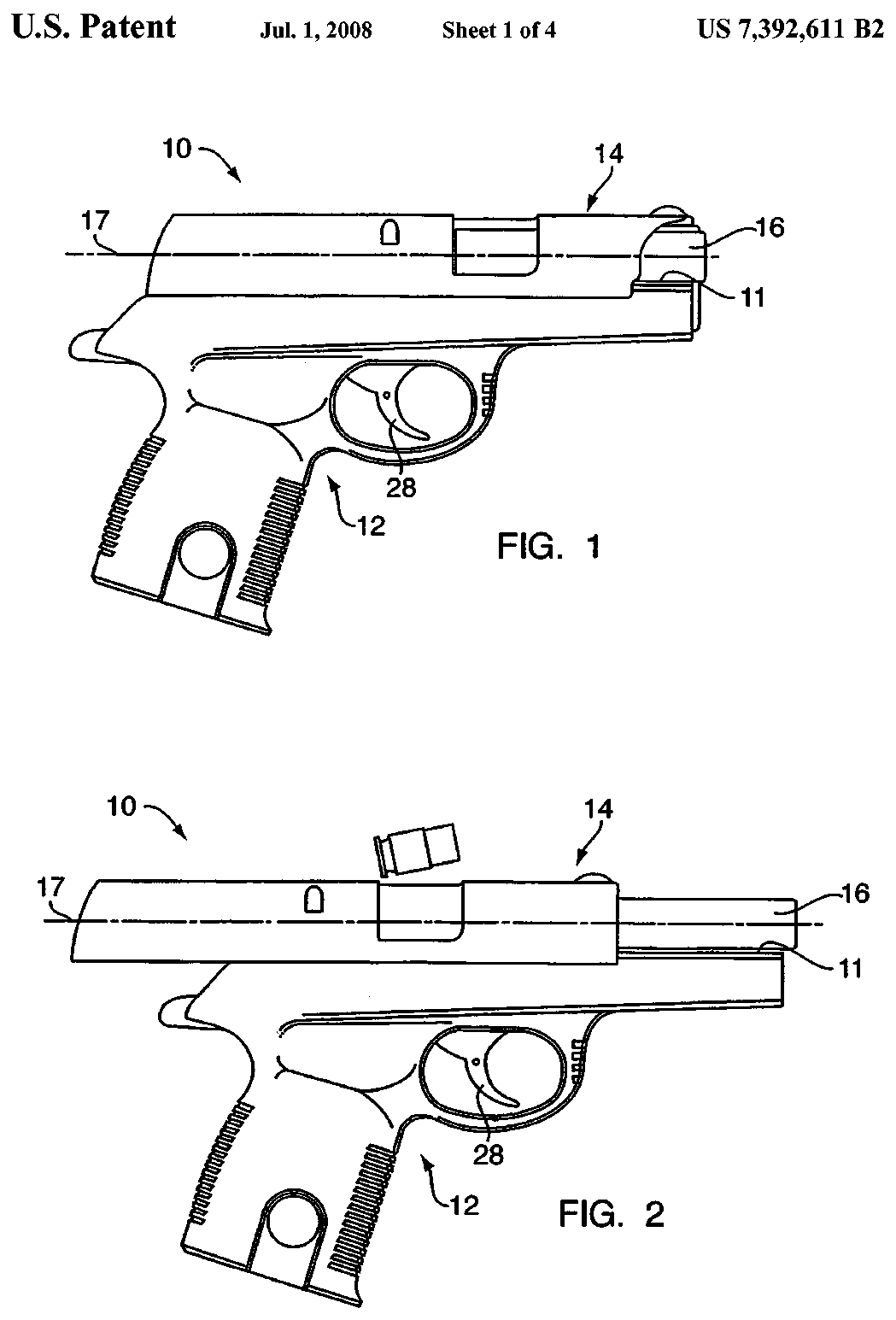
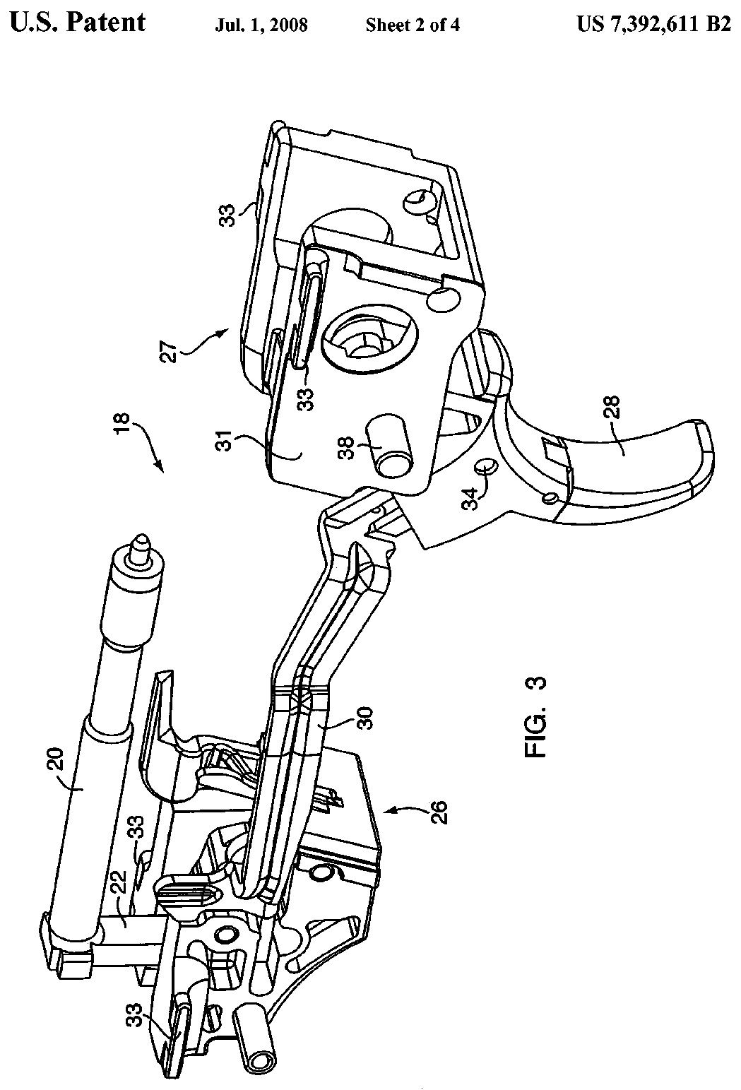
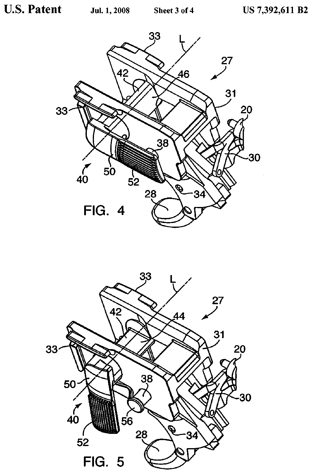
US Patent 7,392,611 — Apparatus and method for firearm takedown
Brett Curry · assigned to Smith & Wesson Corp. · filed 2005-12-22 · granted 2008-07-01. Full patent (USPTO)
The M&P takedown system: the takedown lever and sear-deactivation lever in the fire control housing that let the slide come off the frame, shown with the slide on the frame in battery and retracted.
Why this is the Smith & Wesson M&P9 M2.0’s patent: listed on the maker’s patent-marking page — Virtual Patent Marking | Smith & Wesson — Smith & Wesson smith-wesson.com [10]: “7,392,611 All M&P® pistols (except M&P® Bodyguard® 380 pistols)”
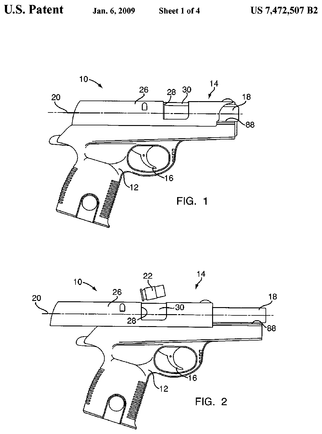
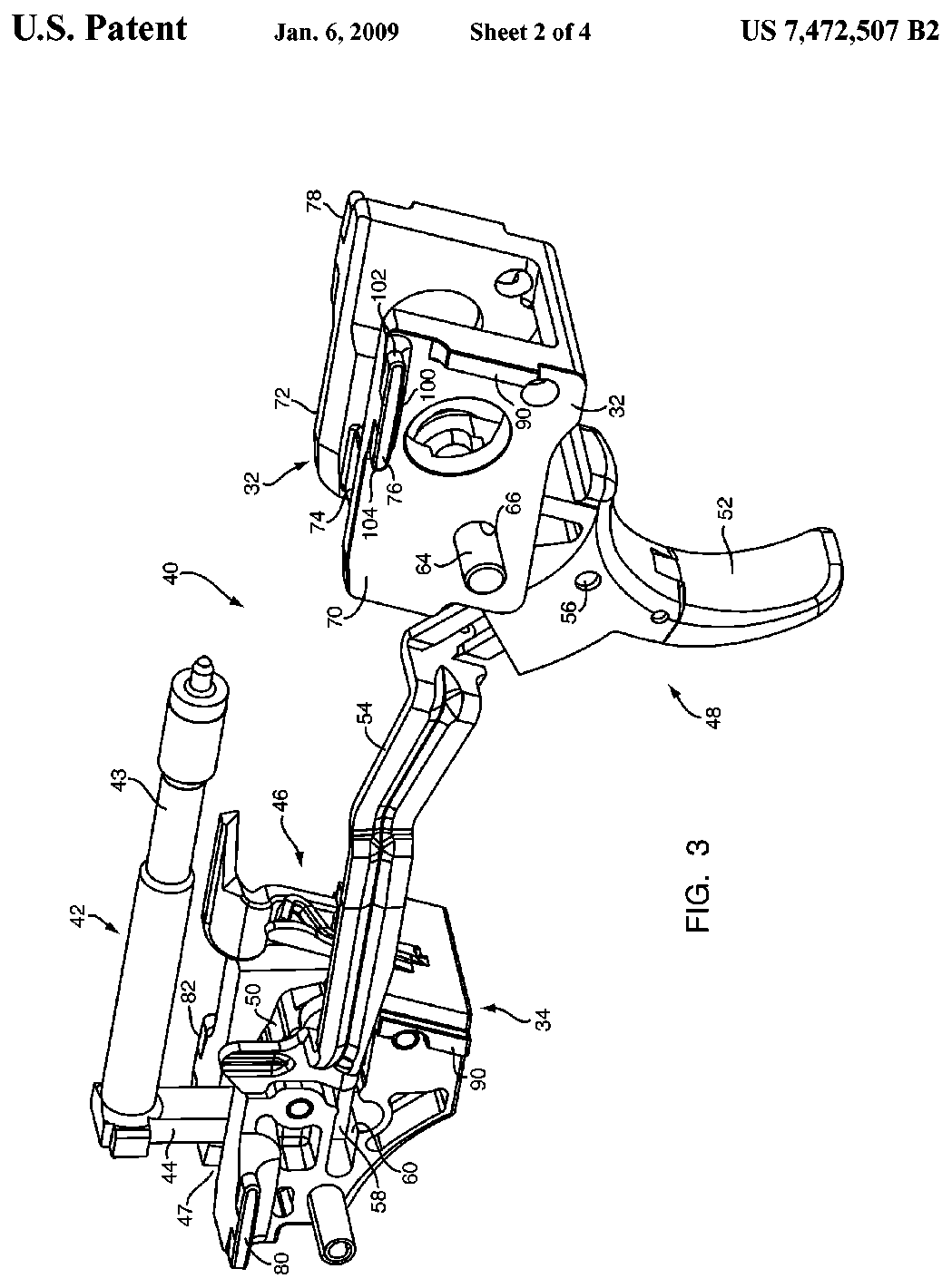
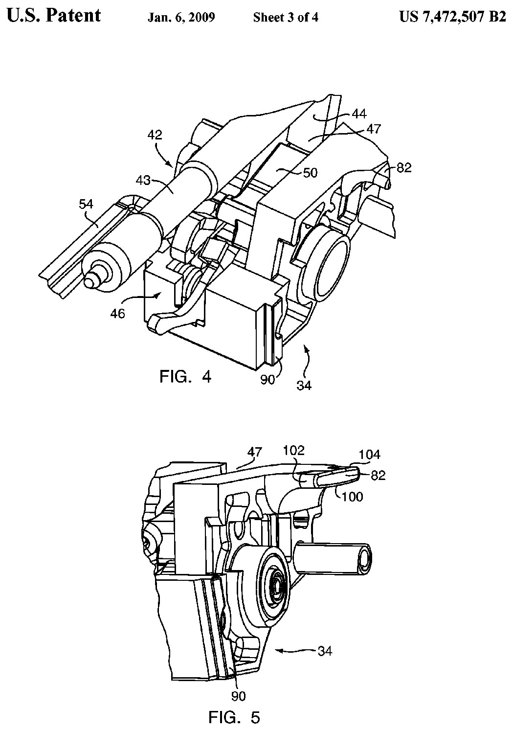
US Patent 7,472,507 — Firearm with modular sear and trigger mechanism housings
Brett Curry, Michael J. Poulin · assigned to Smith & Wesson Corp. · filed 2005-12-22 · granted 2009-01-06. Full patent (USPTO)
The M&P frame with its separate modular sear housing and trigger mechanism housing that drop into receptacles in the polymer frame.
Why this is the Smith & Wesson M&P9 M2.0’s patent: listed on the maker’s patent-marking page — Virtual Patent Marking | Smith & Wesson — Smith & Wesson smith-wesson.com [10]: “7,472,507 M&P® M2.0™, M&P®9, M&P®40, M&P®357 and M&P®45 pistols”
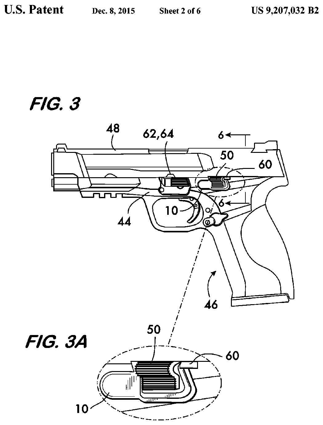
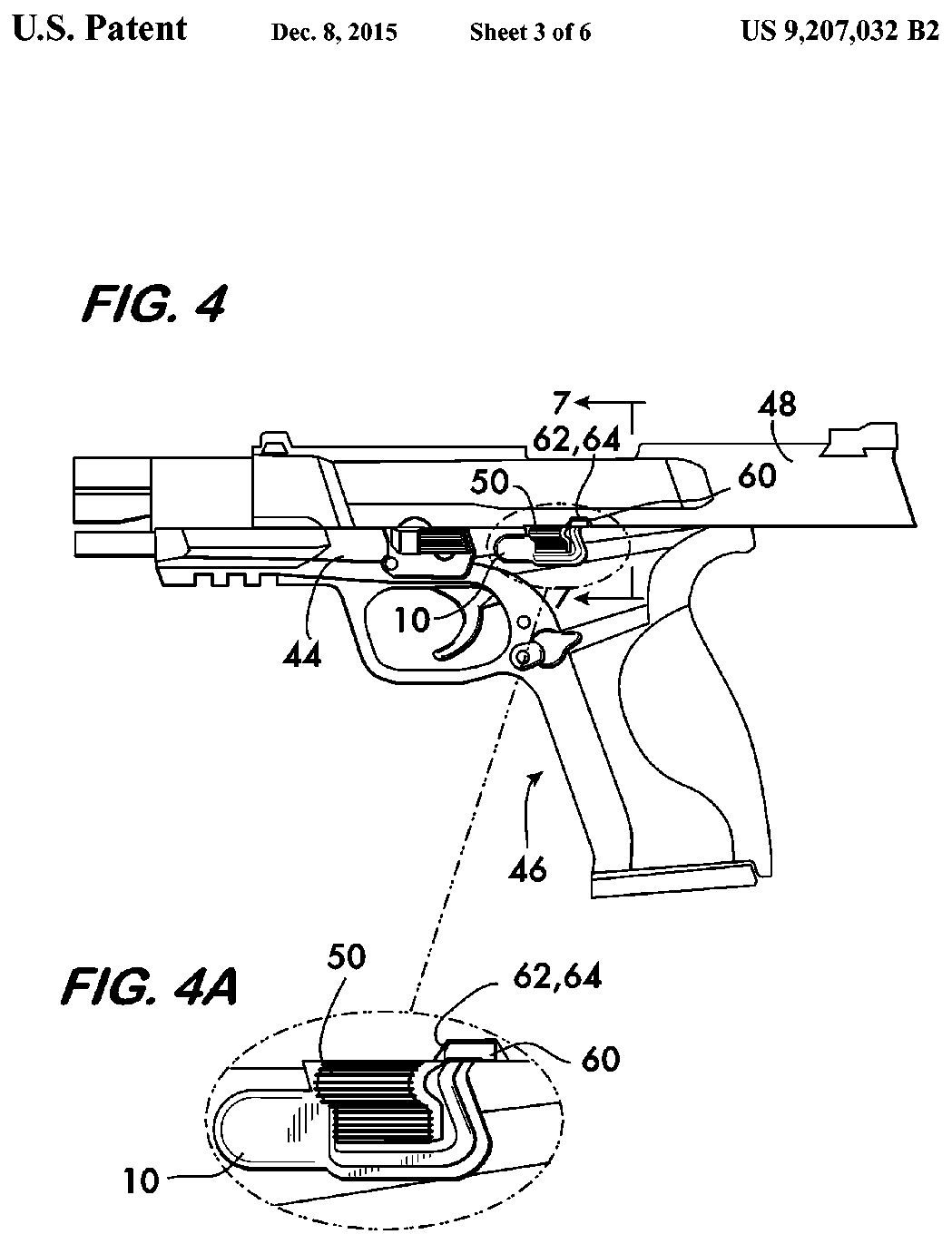
US Patent 9,207,032 — Slide stop support mechanism
Brett Curry · assigned to Smith & Wesson Corp. · filed 2014-03-31 · granted 2015-12-08. Full patent (USPTO)
The slide stop and its retention/support mechanism on the M&P M2.0 frame, shown on a full side view of the pistol in battery and with the slide locked back.
Why this is the Smith & Wesson M&P9 M2.0’s patent: listed on the maker’s patent-marking page — Virtual Patent Marking | Smith & Wesson — Smith & Wesson smith-wesson.com [10]: “9,207,032 M&P® M2.0™ products; M&P® Pistols (only used on the version sent to the North Carolina Highway Patrol in 2013)”
Torque specifications
No sourced torque values from the manufacturer are recorded for this firearm. Where a fastener has a specified torque — action screws, scope bases, muzzle devices, barrel nuts — get it from the manufacturer or a gunsmith rather than estimating it.
What the manufacturer does say: The manufacturer's documents give no torque value. They say: "Using the appropriate screws (see table on pages 44-45 for details), tighten the sight down onto the slide adapter (FIGURES 90 and 91) using a 5/64˝ hex wrench." (Safety & Instruction Manual, M&P M2.0 Polymer-Frame Pistols (p/n 3006363, REV M&P_M2.0_POLYMER_FRAME_021525), linked from smith-wesson.com M&P9 M2.0 Optic Ready product page, p. 43) "UNLOAD THE PISTOL AND TIGHTEN THE SCREWS; IF THE SCREWS WILL NOT TIGHTEN CALL THE CUSTOMER SERVICE DEPARTMENT FOR ASSISTANCE AT 1-800-331-0852, EXT. 4125." (Safety & Instruction Manual, M&P M2.0 Polymer-Frame Pistols (p/n 3006363, REV M&P_M2.0_POLYMER_FRAME_021525), linked from smith-wesson.com M&P9 M2.0 Optic Ready product page, p. 42)
Reported by other sources — not the manufacturer
| Fastener | Torque | Who says so, and their words | Where it comes from |
|---|---|---|---|
| Optic plate to slide screws (6-32 x 5/16 T15) S&W M&P M2.0 / M&P CORE 2.0 optics-ready slide with Forward Controls Design OPF-SW, RMR plate |
25 in-lb 2.8 N·m · 2.1 ft-lb |
Reported by Forward Controls Design “Torque value for included 6-32 x 5/16 T15 plate to slide screws: 25 in ·lb.” |
OPF-SW, RMR (product page) — Forward Controls Design forwardcontrolsdesign.com [3] |
| Optic (Trijicon RMR) to plate screws S&W M&P M2.0 CORE with FCD OPF-SW, RMR plate, Trijicon RMR |
13 in-lb 1.5 N·m · 1.1 ft-lb |
Reported by Forward Controls Design “Torque value for RMR to plate: 13 in ·lb.” |
OPF-SW, RMR (product page) — Forward Controls Design forwardcontrolsdesign.com [3] |
| Red-dot optic mounting screws (6-32 flat head, supplied) into EGW rear-dovetail sight mount Smith & Wesson M&P 2.0 Full Size / Compact (non-optics-ready; not C.O.R.E.) with the EGW 'Red Dot Sight Mount for Smith and Wesson (S&W) M&P (fits Trijicon RMR / SRO, Holosun 407c / 507c)' (replaces t |
15 in-lb 1.7 N·m · 1.2 ft-lb |
Reported by Evolution Gun Works (EGW) Remove the rear sight, install the EGW mount in the dovetail, tighten the set screw if applicable, place the optic on the mount, then apply blue Loctite and torque the optic screws. Threadlocker: Blue Loctite on the provided mounting screws (EGW instructions) “Torque mounting screws to 15in/lbs” |
Red Dot Sight Mount for Smith and Wesson (S&W) M&P (fits Trijicon RMR / SRO, Holosun 407c / 507c) (EGW product page, installation instructions section) — Evolution Gun Works (EGW) egwguns.com [6] |
| Red-dot optic mounting screws (supplied) into EGW rear-dovetail sight mount (Docter/Venom/Viper/FastFire footprint) Smith & Wesson M&P 2.0 Full Size / Compact (non-optics-ready; not C.O.R.E.) with the EGW 'Smith & Wesson M&P Red Dot Mount | EGW Vortex Venom Plate' (replaces the rear sight) |
15 in-lb 1.7 N·m · 1.2 ft-lb |
Reported by Evolution Gun Works (EGW) Remove the rear sight, install the EGW mount in the dovetail, tighten the set screw if applicable, place the optic on the mount, then apply blue Loctite and torque the optic screws. Threadlocker: Blue Loctite on the provided mounting screws (EGW instructions) “Torque mounting screws to 15 in/lbs” |
Smith & Wesson M&P Red Dot Mount | EGW Vortex Venom Plate (EGW product page, installation instructions section) — Evolution Gun Works (EGW) egwguns.com [7] |
| XS optic plate to slide screws S&W M&P M2.0 Optics Ready Full Size with the XS Smith & Wesson Optic Plate (RMR or ACRO footprint) (fitment per XS product page https://xssights.com/products/smith-wesson-optic-plate-fits-rmr.html) |
6–8 in-lb 0.68–0.9 N·m · 0.5–0.67 ft-lb |
Reported by XS Sights Degrease, apply the supplied blue threadlocker, start both screws before torquing, then tighten one at a time. XS recommends 12-24 h Loctite cure before shooting and witness-marking the screws. Threadlocker: Supplied blue threadlocker “Tighten screws one at a time to a final torque spec of 6-8 inch pounds.” |
XS Sights — Installation Instructions, Optic Plate for S&W (PDF linked from the XS product page) — XS Sights, PDF p. 1, step 11 xssights.com [8] |
| Optic to XS optic plate screws S&W M&P M2.0 Optics Ready Full Size with the XS Smith & Wesson Optic Plate (RMR or ACRO footprint) (fitment per XS product page https://xssights.com/products/smith-wesson-optic-plate-fits-rmr.html) |
6–8 in-lb 0.68–0.9 N·m · 0.5–0.67 ft-lb |
Reported by XS Sights Degrease, apply the supplied blue threadlocker, start both screws before torquing, then tighten one at a time. XS recommends 12-24 h Loctite cure before shooting and witness-marking the screws. Threadlocker: Supplied blue threadlocker “Tighten optic to plate screws with a final torque spec of 6-8 inch pounds.” |
XS Sights — Installation Instructions, Optic Plate for S&W (PDF linked from the XS product page) — XS Sights, PDF p. 1, step 13 xssights.com [8] |
| DeltaPoint Pro M4x.7x15.8mm Torx screws through Leupold mount base into dovetail S&W M&P with Leupold DeltaPoint Pro on the Leupold M&P base/dovetail (SKU 170909; set screws in the dovetail per Leupold) or the M&P C.O.R.E plate (SKU 171203) |
25 in-lb 2.8 N·m · 2.1 ft-lb |
Reported by Leupold & Stevens, Inc. Remove the rear sight, fit the Leupold dovetail (part number up) in its place, set the mount base over it, seat the DeltaPoint Pro on the base posts, then torque the two Torx screws (press-fit). “Secure the screws by applying 25 in-lbs of torque.” |
Leupold DeltaPoint Pro Reflex Sight — Operating Instructions (Part #120278, artwork #120279P; English text with French translation) — Leupold & Stevens, Inc., PDF p. 1 (Installation section; mount li leupold.com [9] |
Materials and factory finish
As stated by Smith & Wesson. Prep, masking and cure depend on these; a polymer or aluminium part, a nitrided or anodised finish, and a blued steel part are each a different job. Variants with other finishes may exist — check the maker's page for the exact SKU on the bench.
| Component | Material | Factory finish | Where it comes from |
|---|---|---|---|
| Frame M&P9 M2.0, full size, 4.25in, no thumb safety, SKU 11521 | POLYMER | — | Smith & Wesson M&P9 M2.0 — product specifications, SKU 11521 — Smith & Wesson Brands, Inc. smith-wesson.com [5] “FRAME MATERIAL … POLYMER” |
| Barrel M&P9 M2.0, full size, 4.25in, no thumb safety, SKU 11521 | STAINLESS STEEL | — | Smith & Wesson M&P9 M2.0 — product specifications, SKU 11521 — Smith & Wesson Brands, Inc. smith-wesson.com [5] “BARREL MATERIAL … STAINLESS STEEL” |
| Whole firearm M&P9 M2.0, full size, 4.25in, no thumb safety, SKU 11521 | — | BLACK The maker states this for the firearm as a whole, not for a named part. | Smith & Wesson M&P9 M2.0 — product specifications, SKU 11521 — Smith & Wesson Brands, Inc. smith-wesson.com [5] “COLOR/FINISH … BLACK” |
| Grips M&P9 M2.0, full size, 4.25in, no thumb safety, SKU 11521 | POLYMER | — | Smith & Wesson M&P9 M2.0 — product specifications, SKU 11521 — Smith & Wesson Brands, Inc. smith-wesson.com [5] “GRIP … POLYMER” |
Parts
No parts list from Smith & Wesson is transcribed for this firearm.
Smith & Wesson's own documents label the parts on these pages — the links open each document at the page:
- Model and features identification (labelled photo of the pistol): Safety & Instruction Manual, M&P M2.0 Polymer-Frame Pistols (p/n 3006363, REV M&P_M2.0_POLYMER_FRAME_021525), linked from smith-wesson.com M&P9 M2.0 Optic Ready product page — Smith & Wesson, p. 12 smith-wesson.canto.com [4]
Function check
- Verify the pistol is unloaded before each check.
- Rack the slide and press the trigger. The striker should release.
- Hold the trigger back, rack the slide, release slowly and confirm the reset click.
- Press the trigger again to confirm the striker releases.
- If equipped with a manual thumb safety, confirm the trigger is blocked when engaged.
- Confirm the slide locks open on an empty magazine and the magazine drops free.
Maintenance
Lubrication points
- Four steel frame rail inserts
- Barrel hood and locking lug
- Outside of the barrel at the muzzle end
- Rear barrel lug where the recoil spring assembly bears
Cleaning notes
Light lubrication only. Keep the striker channel dry and free of solvent.
Suggested inspection interval: roughly every 5000 rounds. This is a general guideline, not a manufacturer specification.
Wear parts to inspect
Recoil spring assembly · Extractor · Magazine springs
Common issues
| Symptom | Likely cause | What to do |
|---|---|---|
| Takedown lever will not rotate down | Slide not locked fully to the rear | Lock the slide fully open on the slide stop and try again. |
| Sear deactivation lever will not rotate | Slide is forward, so the sear is still under spring load | Lock the slide to the rear first, then rotate the lever. |
Also covers
The procedures above are reported to apply to: M&P9 M2.0 Compact · M&P40 M2.0 · M&P45 M2.0 · M&P9 Shield (with differences). Verify against the manual for your specific model.
Similar manual of arms
Sourcing
- Confidence
- high — Cross-checked against a primary source such as the manufacturer's manual or an issuing military technical manual.
- Verification
- Checked against the manufacturer manual
- Last updated
- 2026-10-29
References
Every source this page draws on, with its web address so you can read it yourself. Numbers in brackets elsewhere on the page point here.
- [1] Safety & Instruction Manual — M&P M2.0 Pistols — Smith & Wesson manufacturer manual primary source
https://assets.contentstack.io/v3/assets/bltb61dcb3c40854cd9/bltfc45074061a5da40/65b26c4ae5c1f34facd9463a/M&P_M2pt0_Manual_013024_3006363.pdf (checked 2026-09-14) - [2] Smith & Wesson Owner's Manuals — Smith & Wesson manufacturer manual primary source
https://www.smith-wesson.com/customer-service/owners-manuals (checked 2026-09-14) - [3] OPF-SW, RMR (product page) — Forward Controls Design website secondary source
https://www.forwardcontrolsdesign.com/OPF-SW-RMR_p_498.html (checked 2026-09-27) - [4] Safety & Instruction Manual, M&P M2.0 Polymer-Frame Pistols (p/n 3006363, REV M&P_M2.0_POLYMER_FRAME_021525), linked from smith-wesson.com M&P9 M2.0 Optic Ready product page — Smith & Wesson manufacturer manual primary source
https://smith-wesson.canto.com/direct/document/mpnqeesbot6j1b2pb3vps0e02d/-DGV9sNoZpfozpwlI4GaxeO4fQw/original?content-type=application%2Fpdf (checked 2026-09-27) - [5] Smith & Wesson M&P9 M2.0 — product specifications, SKU 11521 — Smith & Wesson Brands, Inc. website primary source
https://www.smith-wesson.com/product/m-p-9-m2.0 (checked 2026-10-03) - [6] Red Dot Sight Mount for Smith and Wesson (S&W) M&P (fits Trijicon RMR / SRO, Holosun 407c / 507c) (EGW product page, installation instructions section) — Evolution Gun Works (EGW) website secondary source
https://egwguns.com/trijicon-rmr-sro-holosun-407c-507c-mount-for-s-w-m-p (checked 2026-10-11) - [7] Smith & Wesson M&P Red Dot Mount | EGW Vortex Venom Plate (EGW product page, installation instructions section) — Evolution Gun Works (EGW) website secondary source
https://egwguns.com/vortex-viper-venom-s-w-m-p-sight-mount-fits-burris-fastfire-and-docter (checked 2026-10-11) - [8] XS Sights — Installation Instructions, Optic Plate for S&W (PDF linked from the XS product page) — XS Sights manufacturer manual secondary source
https://xssights.com/content/Install%20Instructions/XS%20S%26W%20Optic%20Plate%20installation%20instructions.pdf (checked 2026-10-11) - [9] Leupold DeltaPoint Pro Reflex Sight — Operating Instructions (Part #120278, artwork #120279P; English text with French translation) — Leupold & Stevens, Inc. manufacturer manual secondary source
https://www.leupold.com/media/manuals/DeltaPoint_Pro_Manual_French_120279P.pdf (checked 2026-10-11) - [10] Virtual Patent Marking | Smith & Wesson — Smith & Wesson website primary source
https://www.smith-wesson.com/company/virtual-patent-marking (checked 2026-10-13) - [11] M&P 2.0 Apex trigger installation Issues. — Northeastshooters.com Forums community anecdotal source
https://www.northeastshooters.com/xen/threads/m-p-2-0-apex-trigger-installation-issues.380517/ (checked 2026-10-29)
Notes: Corrected against the factory manual on 2026-09-14. The core claim — that the sear deactivation lever lets you field strip without a trigger press — was confirmed. Two required steps were missing: the frame tool is stored in the bottom of the grip and is removed by turning it 90 degrees, and the palmswell backstrap insert must come off before the sear deactivation lever is reachable. The manual's reassembly checks on the sear lever and slide stop positions were also added.