← All firearms · Printable work order
Beretta 92FS
- easy
- Shop tier 2
- high confidence
- Pistol
- da sa
- open slide
- service pistol
- decocker
- toolless field strip
field strip ~1 min · reassembly ~2 min · detail strip ~25 min
Specifications
- Manufacturer
- Beretta
- Origin
- Italy
- Category
- Pistol
- Action
- Hammer-fired, short recoil
- Calibers
- 9x19mm Parabellum
- Capacity
- 15+1 with the standard magazine
- Production
- 1975–present (in-production)
- Also known as
- Beretta M9, 92F, 92FS Inox
Model-specific safety
- The recoil spring and spring guide are under tension when the slide assembly comes off. The manual specifies pressing them slightly, then lifting them out and letting the spring stretch slowly — not releasing them abruptly.
- The locking block is a wear part on this design. Inspect it for cracks at the radius every time the pistol is stripped.
- The safety/decocking lever drops the hammer when rotated down. Never use the decocker as a substitute for verifying the chamber is empty.
- The manual states that no further disassembly beyond the field strip is recommended unless done by a competent gunsmith.
- On Model G pistols the lever is a decocker only, with no safety detent. Identify which variant you have.
If it will not go back together
Common ways this firearm resists reassembly, and what is actually wrong. Forcing a part that will not seat is how firearms get damaged.
-
The slide will not come off the frame.
Why The disassembly latch release button is not pressed while the lever rotates.
Fix Press the disassembly lever release button with your forefinger and rotate the lever downward with your thumb until it stops, then run the slide forward.
Under spring tension
- Recoil spring and guide
- Magazine spring if disassembled
Easily lost parts
Locking block plunger · Recoil spring guide
Tools
No tools required for the field strip.
Shop difficulty
Shop tier 2 Tier 2 — moderate among pistols, for the full job: strip to the parts that get coated and put it back together working. 62 line items (73 pieces) in American Rifleman's parts legend; punch-and-screwdriver work, but the slide-mounted safety hides two captive plungers and springs that fly when the lever comes out and must be held while it goes back in, and the trigger bar spring and hammer spring are released under tension. A classic Tier 2 detail strip.
Parts: 62 numbered parts (Complete pistol incl. magazine (keys 1-62; 73 pieces counting stocks (2), stock screws (4), bushings (4), washers (4) and right safety lever spring pins (2))), from "U.S. Pistol, M9" Beretta Model 92FS (Exploded View) — American Rifleman (NRA) americanrifleman.org [9].
Bench time: about 30 min to strip, 45 min to rebuild (estimate). Estimate for an experienced tech with the right tools, detail strip to coatable parts (slide internals, frame pins, trigger group, sights) and rebuild to a function-checked gun; scale used across pistols: Glock-pattern 15/20 min, other strikers 20-30/25-40, DA/SA hammer guns 30-35/45-50, Hi-Power, Colt 1903 and Mark 23 40-45/60-75.
Small parts: 10 pins, 14 springs, 5 detents or plungers (counted from the parts list in partCount)
What comes off for coating
- Slide: right safety lever (2 spring pins), left safety lever with safety plunger/spring and trigger bar release plunger/spring, firing pin and spring, firing pin block and spring, extractor, pin and spring, rear sight — 1/16 in. roll-pin punch, sight pusher
- Barrel: locking block, locking block plunger and retaining pin, recoil spring and guide
- Frame: stocks, magazine release and spring, trigger bar and spring, slide catch and spring, trigger, pin and spring, hammer spring cap, pin, hammer spring, hammer, pin and strut, sear, spring and pin, ejector and hammer release lever (pins), firing pin block lever, disassembly latch and button — punch set, brass hammer
Special tools
- Small roll-pin punches (1/16 in. and 3/32 in.) — Right safety lever pins, hammer spring cap pin, extractor pin
- Bench block — Supporting the slide while drifting the safety lever pins
- Dovetail sight pusher — Rear sight (front sight is integral)
Known pain points
- Removing the left safety lever releases the safety plunger and its spring plus the trigger bar release plunger and its spring, small captive parts that are easily lost. (both)
Source: "U.S. Pistol, M9" Beretta Model 92FS (Exploded View) — American Rifleman (NRA) americanrifleman.org [9] — “pull the left safety lever (14) up and to the left for removal, taking care not to lose the safety plunger (56) and its spring (55), the trigger bar release plunger (10) and its spring (11).” - Reinstalling the slide safety takes three hands at once: the firing pin safety plunger and the firing pin plunger held down while the lever is rotated, with two spring-loaded detents to capture. (reassembly)
Owners report: DIY: Installing a Wilson Combat low-profile safety on a Beretta 92 — Canadian Gun Nutz canadiangunnutz.com [10] — “You will have to depress the firing pin safety plunger (firing pin catch) while pressing the firing pin plunger down while simultaneously flipping the safety to the 10 o'clock position.” - The trigger bar spring has to be unhooked from its groove and eased out under tension, and hooked back into the trigger bar on reassembly. (both)
Source: "U.S. Pistol, M9" Beretta Model 92FS (Exploded View) — American Rifleman (NRA) americanrifleman.org [9] — “Depress the upper arm of the trigger bar spring (26) from its groove in the underside of the trigger bar (25) and slowly release the spring out and away to the right.” - The hammer spring is held by a cap and spring pin; drifting the pin releases the hammer spring under tension, and the cap must be compressed again to repin it. (both)
Source: "U.S. Pistol, M9" Beretta Model 92FS (Exploded View) — American Rifleman (NRA) americanrifleman.org [9] — “Drift out the hammer spring cap spring pin (43) to free the cap (37) and slowly release tension on the hammer spring (36) to remove.”
See also 1 documented reassembly problem and their fixes.
Fit or check on rebuild
- Safety/decocker function and hammer drop check — The slide safety holds two detents and the firing pin plunger; a mis-seated part leaves the decocker or firing pin block inoperative
Source: DIY: Installing a Wilson Combat low-profile safety on a Beretta 92 — Canadian Gun Nutz canadiangunnutz.com [10] — “With the firearm unloaded, flip the safety to the on position. The hammer should drop and the trigger should move through the full range yet remain inoperable” - Disassembly latch fully rotated up — A latch not rotated fully up lets the slide come off while shooting
- Sight position / re-zero — Drift or pressed sights moved for coating shift point of impact unless witness-marked and returned to the same spot
- Full function check (trigger reset, safeties, slide lock-back, drop of striker/hammer only on trigger) — Standard after any fire-control strip; confirms springs and sears went back correctly
This is Pew-Takedown's rating, not the manufacturer's. How tiers are rated. Forum reports are owners' experience, not specifications.
Procedures
Clear and Make Safe
Clear & Make Safe- Point the muzzle in a safe direction and keep your finger off the trigger.
- Press the magazine release and remove the magazine.Removed at this step:
Magazine - Retract the slide fully to eject any chambered round, and lock it open with the slide stop.
- Inspect the chamber visually and physically. The open-top slide makes this easy — use that advantage.WarningThe open-slide design does not remove the need for a physical check.
- Remove all live ammunition from the work area.
Field Strip
Field StripThe factory manual's sequence. One of the fastest field strips of any service pistol, and no tools.
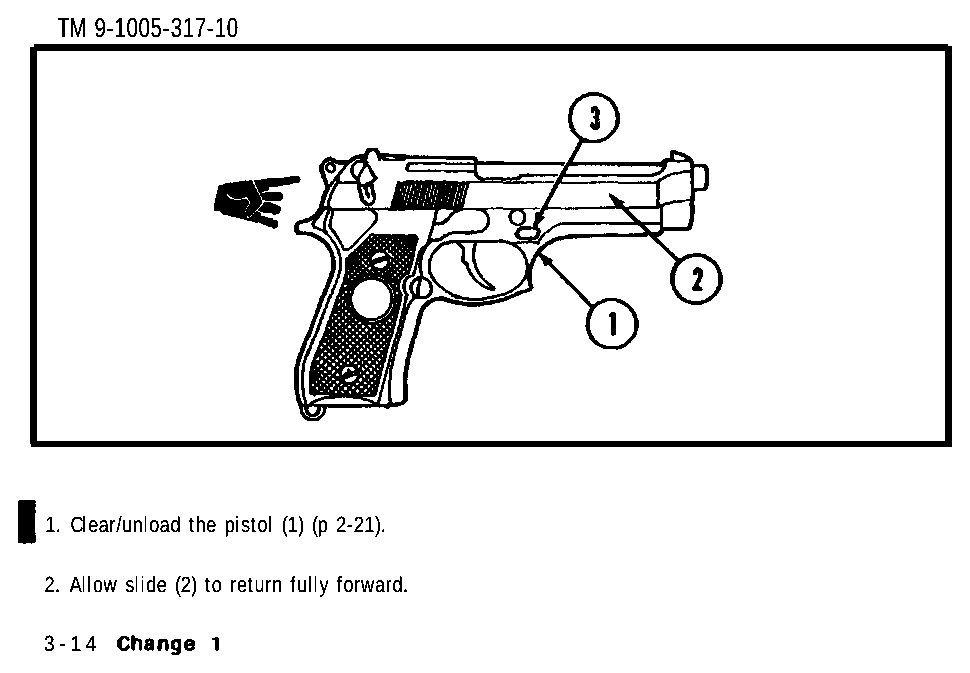
- Complete the Clear and Make Safe procedure and let the slide return forward.
- Depress the magazine release button and remove the magazine if it is not already out.Removed at this step:
Magazine - Hold the pistol in your right hand. With your left forefinger press the disassembly latch release button on the right side of the frame, and with your left thumb rotate the disassembly latch clockwise until it stops.TipThe latch is on the left side of the frame and rotates downward and forward. The manual describes the motion as clockwise.
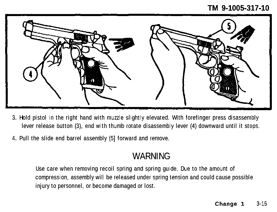
M9 field strip — disassembly lever and slide removal Pressing the disassembly lever release button and rotating the lever down, then running the slide off the front. TM 9-1005-317-10 — Operator's Manual, Pistol, Semiautomatic, 9mm, M9, p.73 — Departments of the Army, Navy and Air Force. Source. Public domain (US Government work). - Pull the slide and barrel assembly forward off the frame, together with the locking block, recoil spring, and spring guide.Removed at this step:
Slide assembly - Press the recoil spring and spring guide slightly.
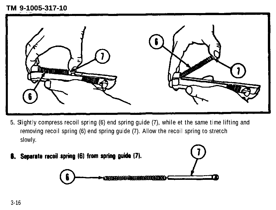
M9 field strip — recoil spring and spring guide Compressing and lifting out the recoil spring and guide. The manual's warning about spring tension applies exactly here. TM 9-1005-317-10 — Operator's Manual, Pistol, Semiautomatic, 9mm, M9, p.74 — Departments of the Army, Navy and Air Force. Source. Public domain (US Government work). - Lift the spring guide and recoil spring out, letting the spring stretch slowly.WarningDo not let the spring go abruptly. The manual specifies easing it out under control.Removed at this step:
Recoil springRecoil spring guide - Press the locking block plunger.
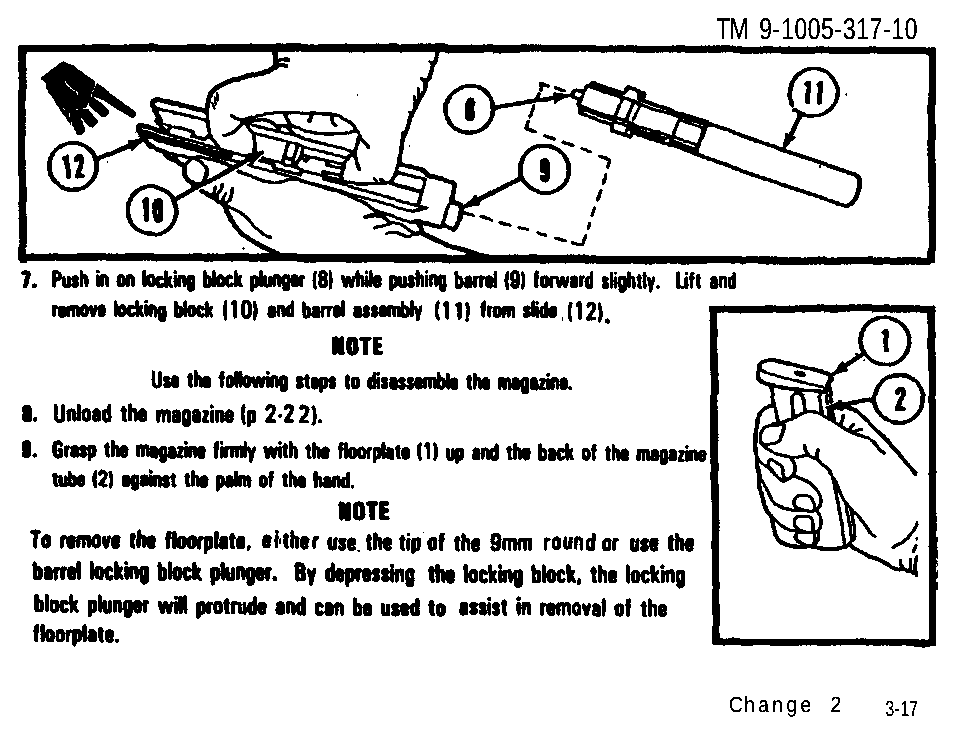
M9 field strip — locking block and barrel Pressing the locking block plunger and lifting the barrel and locking block out of the slide. TM 9-1005-317-10 — Operator's Manual, Pistol, Semiautomatic, 9mm, M9, p.75 — Departments of the Army, Navy and Air Force. Source. Public domain (US Government work). - Take the barrel and locking block assembly out of the slide.Removed at this step:
Barrel and locking block assembly - Stop here. The manual states that no further disassembly is recommended unless carried out by a competent gunsmith.WarningGoing further into the frame or slide is gunsmith work on this design.
Disassemble the magazine
Detail StripTM 9-1005-317-10 para 3-3, steps 8–12 — an operator-level task in the M9 operator's manual, done after the field strip.
Follows TM 9-1005-317-10 Operator's Manual: Pistol, Semiautomatic, 9mm, M9 (reprint including Changes 1–3) — Departments of the Army, Navy and Air Force; Headquarters, Marine Corps; Commandant, Coast Guard, para 3-3, steps 8–12 (pp. 3-17 to 3-18) archive.org [5]
- Unload the magazine.
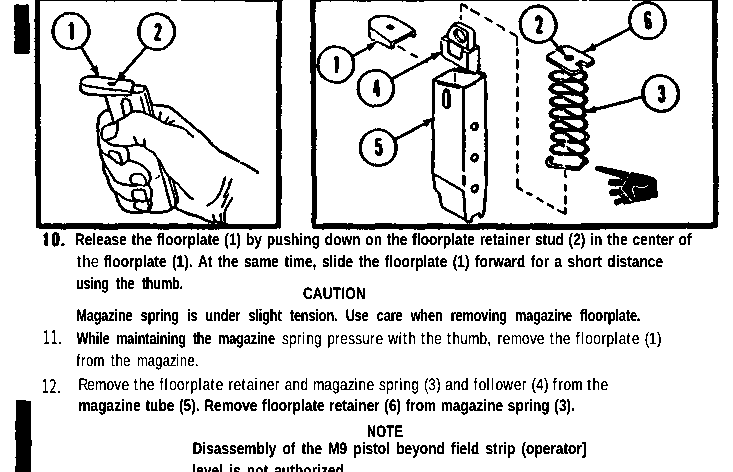
- Grasp the magazine firmly with the floorplate up and the back of the magazine tube against the palm of your hand.
- Push down on the floorplate retainer stud in the center of the floorplate and, at the same time, slide the floorplate forward a short distance with your thumb.WarningMagazine spring is under slight tension. Use care when removing magazine floorplate.TipThe manual's note: to press the stud, use either the tip of a 9mm round or the barrel locking block plunger — depressing the locking block makes the plunger protrude so it can be used as a tool.
- While keeping pressure on the magazine spring with your thumb, remove the floorplate from the magazine.Removed at this step:
Floorplate - Remove the floorplate retainer, magazine spring and follower from the magazine tube.Removed at this step:
Floorplate retainerMagazine springFollower - Remove the floorplate retainer from the magazine spring.
Reassemble the magazine
Detail ReassemblyTM 9-1005-317-10 para 3-6, steps 7–12, operator level.
Follows TM 9-1005-317-10 Operator's Manual: Pistol, Semiautomatic, 9mm, M9 (reprint including Changes 1–3) — Departments of the Army, Navy and Air Force; Headquarters, Marine Corps; Commandant, Coast Guard, para 3-6, steps 7–12 (pp. 3-30 to 3-32) archive.org [5]
- Insert the follower into the top coil of the magazine spring — the top coil is the one with an upward and forward pointing end.TipMake sure the notches on the follower and the magazine tube are on the same side.
- Insert the magazine spring with the follower into the magazine tube.
- Turn the magazine bottom up with its back side against the palm of your hand.
- Attach the floorplate retainer to the bottom spring coil and center it.WarningAfter insertion, spring tension must be maintained using the thumb. Do not place the lips of the magazine tube on a hard surface during reassembly.
- Push and hold the magazine spring and floorplate retainer down and, at the same time, slide the floorplate over the side walls until fully seated; a click indicates it is seated.
- Insert the magazine into the magazine well carefully until it clicks into the locked position.
Reassembly
Reassembly- Set the barrel and locking block assembly into the inverted slide, locking block down, and seat it fully forward.
- Insert the recoil spring and guide through the spring, seat the guide into its cut in the barrel lug, and press it down into the slide.
- Set the slide onto the frame rails from the front and push it rearward until it seats fully.WarningBefore placing the slide on the frame, make sure the hammer is uncocked and the firing pin block lever is down, and the decocking/safety lever is in the safe (down) position. If the hammer is cocked, lower it carefully by hand. Do not pull the trigger while placing the slide on the frame.
- Rotate the disassembly latch lever upward until it clicks and the release button pops back out.
- Rack the slide to confirm free travel, then perform the function check.WarningIf the disassembly latch is not fully rotated up, the slide can come off the frame under recoil.
Diagrams
public domainThese are reproduced from government technical manuals, which are not subject to copyright. Manufacturer manual diagrams are not reproduced here — the entry links to the manual instead.
Torque specifications
No sourced torque values from the manufacturer are recorded for this firearm. Where a fastener has a specified torque — action screws, scope bases, muzzle devices, barrel nuts — get it from the manufacturer or a gunsmith rather than estimating it.
What the manufacturer does say: The manufacturer's documents give no torque value. They say: "When the adjustable rear sight base is centered in the slide, lock it in position screwing the two dowels to the end, without forcing, using the Allen key supplied." (Beretta 90 Series Pistol User Manual (92/96), PDF p. 30 (adjustable rear sight, target/competition versions))
Reported by other sources — not the manufacturer
| Fastener | Torque | Who says so, and their words | Where it comes from |
|---|---|---|---|
| Grip screws Beretta 92F/92FS/92G/92D/96/M9/M9A1/92A1 with Hogue grips (page "Will Fit" list includes 92FS); stock screws, no star washers |
12 in-lb 1.4 N·m · 1 ft-lb |
Reported by Hogue, Inc. Threadlocker: Blue Loctite suggested on the threads “- Grip screws should be torqued to 12 inch/lbs. Blue Loctite is suggested on the threads” |
Beretta 92/96 Series OverMolded Rubber Grip with Finger Grooves (product page) — Hogue, Inc. hogueinc.com [4] |
| Red-dot optic mounting screws (6-32 flat head, supplied) into EGW rear-dovetail sight mount Beretta 92FS / 92FS Inox / M9 / M9A1 (non-optics-ready, rear-dovetail slides) with the EGW 'Trijicon RMR / SRO, Holosun 407c / 507c Mount for Beretta 92' (replaces the rear sight; for Trijicon RMR/SRO |
15 in-lb 1.7 N·m · 1.2 ft-lb |
Reported by Evolution Gun Works (EGW) Remove the rear sight, install the EGW mount in the dovetail, tighten the set screw if applicable, place the optic on the mount, then apply blue Loctite and torque the optic screws. Threadlocker: Blue Loctite on the provided mounting screws (EGW instructions) “Torque mounting screws to 15in/lbs” |
Trijicon RMR / SRO, Holosun 407c / 507c Mount for Beretta 92 (EGW product page, installation instructions section) — Evolution Gun Works (EGW) egwguns.com [6] |
| Red-dot optic mounting screws (supplied) into EGW rear-dovetail sight mount (Docter/Venom/Viper/FastFire footprint) Beretta 92FS / 92FS Inox / M9 / M9A1 (non-optics-ready, rear-dovetail slides) with the EGW 'Beretta 92 Red Dot Mount | Fits Vortex Venom, Viper, FastFire' (replaces the rear sight) |
15 in-lb 1.7 N·m · 1.2 ft-lb |
Reported by Evolution Gun Works (EGW) Remove the rear sight, install the EGW mount in the dovetail, tighten the set screw if applicable, place the optic on the mount, then apply blue Loctite and torque the optic screws. Threadlocker: Blue Loctite on the provided mounting screws (EGW instructions) “Torque optic screws to 15 in/lbs” |
Beretta 92 Red Dot Mount | Fits Vortex Venom, Viper, FastFire (EGW product page, installation instructions section) — Evolution Gun Works (EGW) egwguns.com [7] |
| DeltaPoint Pro M4x.7x15.8mm Torx screws through Leupold mount base into dovetail Beretta 92 with Leupold DeltaPoint Pro on the Leupold Beretta 92 base/dovetail (SKU 170902) |
25 in-lb 2.8 N·m · 2.1 ft-lb |
Reported by Leupold & Stevens, Inc. Remove the rear sight, fit the Leupold dovetail (part number up) in its place, set the mount base over it, seat the DeltaPoint Pro on the base posts, then torque the two Torx screws (press-fit). “Secure the screws by applying 25 in-lbs of torque.” |
Leupold DeltaPoint Pro Reflex Sight — Operating Instructions (Part #120278, artwork #120279P; English text with French translation) — Leupold & Stevens, Inc., PDF p. 1 (Installation section; mount li leupold.com [8] |
Materials and factory finish
As stated by Beretta. Prep, masking and cure depend on these; a polymer or aluminium part, a nitrided or anodised finish, and a blued steel part are each a different job. Variants with other finishes may exist — check the maker's page for the exact SKU on the bench.
| Component | Material | Factory finish | Where it comes from |
|---|---|---|---|
| Frame 92FS standard models | Light alloy | Sandblasted and Anodized black | Beretta 90 Series Pistol User Manual (92/96) — Fabbrica d'Armi Pietro Beretta dam.beretta.com [1] “FRAME: Light alloy. Sandblasted and Anodized black.” |
| Frame 92FS Inox | — | Anodized grey | Beretta 90 Series Pistol User Manual (92/96) — Fabbrica d'Armi Pietro Beretta dam.beretta.com [1] “FRAME: … Models Inox: Anodized grey.” |
| Slide 92FS standard models | Steel | phosphatized and Bruniton coated | Beretta 90 Series Pistol User Manual (92/96) — Fabbrica d'Armi Pietro Beretta dam.beretta.com [1] “SLIDE, BARREL: Steel, phosphatized and Bruniton coated.” |
| Barrel 92FS standard models | Steel | phosphatized and Bruniton coated | Beretta 90 Series Pistol User Manual (92/96) — Fabbrica d'Armi Pietro Beretta dam.beretta.com [1] “SLIDE, BARREL: Steel, phosphatized and Bruniton coated. Inside chromium-plated barrel.” |
| Slide 92FS Inox | Stainless steel | sand-blasted | Beretta 90 Series Pistol User Manual (92/96) — Fabbrica d'Armi Pietro Beretta dam.beretta.com [1] “SLIDE, BARREL: … Models Inox: Stainless steel, sand-blasted.” |
| Barrel 92FS Inox | Stainless steel | sand-blasted | Beretta 90 Series Pistol User Manual (92/96) — Fabbrica d'Armi Pietro Beretta dam.beretta.com [1] “SLIDE, BARREL: … Models Inox: Stainless steel, sand-blasted.” |
| Grips | Plastic | checkered and sand-blasted matte | Beretta 90 Series Pistol User Manual (92/96) — Fabbrica d'Armi Pietro Beretta dam.beretta.com [1] “GRIPS: Plastic, checkered and sand-blasted matte.” |
Function check
- Verify the pistol is unloaded before each check.
- With the safety/decocker in the fire position and the hammer down, press the trigger. The hammer should rise and fall in double action.
- Cock the hammer, then rotate the safety/decocking lever down. The hammer should fall to the safe position and the trigger should be disconnected.
- With the lever still down, press the trigger. Nothing should happen.
- Return the lever to fire, rack the slide, and press the trigger. The hammer should fall in single action.
- Hold the trigger back, rack the slide, release slowly for the reset, and press again.
- Confirm the slide locks open on an empty magazine and that the magazine drops free.
Maintenance
Lubrication points
- Frame rails and matching slide grooves
- Locking block lugs and the recesses they engage in the slide
- Barrel exterior at the muzzle bushing area
- Hammer pivot and sear contact areas
- Locking block plunger
Cleaning notes
Pay particular attention to the locking block and its frame recesses — carbon builds up there and accelerates wear.
Suggested inspection interval: roughly every 5000 rounds. This is a general guideline, not a manufacturer specification.
Wear parts to inspect
Locking block (inspect for cracks at the radius) · Recoil spring · Trigger bar spring · Extractor
Common issues
| Symptom | Likely cause | What to do |
|---|---|---|
| Slide comes off the frame while shooting | Disassembly latch not rotated fully up during reassembly | Always confirm the latch is fully up and the release button has popped back out before loading. |
| Failures to feed or extract appearing suddenly after a few thousand rounds | Cracked locking block | Inspect the locking block for cracks and replace it. Many armorers replace it preventively every 15,000-20,000 rounds. see a gunsmith |
| Recoil spring guide will not seat | Barrel not fully forward in the slide | Seat the barrel assembly all the way forward before installing the guide. |
Also covers
The procedures above are reported to apply to: Beretta M9 · Beretta 92FS Inox · Beretta 96 (.40 S&W) · Beretta M9A1 · Beretta 92X (with differences). Verify against the manual for your specific model.
Similar manual of arms
Sourcing
- Confidence
- high — Cross-checked against a primary source such as the manufacturer's manual or an issuing military technical manual.
- Verification
- Checked against the manufacturer manual
- Last updated
- 2026-10-29
References
Every source this page draws on, with its web address so you can read it yourself. Numbers in brackets elsewhere on the page point here.
- [1] Beretta 90 Series Pistol User Manual (92/96) — Fabbrica d'Armi Pietro Beretta manufacturer manual primary source
https://dam.beretta.com/content/dam/beretta-usa/user-manuals/90_Series_Manual.pdf (checked 2026-09-14) - [2] Beretta Firearms User Manuals — Fabbrica d'Armi Pietro Beretta manufacturer manual primary source
https://www.beretta.com/en/services/beretta-services/user-manuals (checked 2026-09-14) - [3] TM 9-1005-317-10: Pistol, Semiautomatic, 9mm, M9 — U.S. Department of the Army military technical manual primary source
- [4] Beretta 92/96 Series OverMolded Rubber Grip with Finger Grooves (product page) — Hogue, Inc. website secondary source
https://www.hogueinc.com/beretta-92-96-series-overmolded-rubber-grip-finger-grooves-black (checked 2026-09-27) - [5] TM 9-1005-317-10 Operator's Manual: Pistol, Semiautomatic, 9mm, M9 (reprint including Changes 1–3) — Departments of the Army, Navy and Air Force; Headquarters, Marine Corps; Commandant, Coast Guard (1985) military technical manual primary source
https://archive.org/download/milmanual-tm-9-1005-317-10---operators-manual-m9-9mm-handgun/tm_9-1005-317-10_-_operators_manual_m9_9mm_handgun.pdf (checked 2026-10-03) - [6] Trijicon RMR / SRO, Holosun 407c / 507c Mount for Beretta 92 (EGW product page, installation instructions section) — Evolution Gun Works (EGW) website secondary source
https://egwguns.com/trijicon-rmr-sro-holosun-407c-507c-mount-for-beretta-92 (checked 2026-10-11) - [7] Beretta 92 Red Dot Mount | Fits Vortex Venom, Viper, FastFire (EGW product page, installation instructions section) — Evolution Gun Works (EGW) website secondary source
https://egwguns.com/vortex-viper-venom-red-dot-sight-mount-for-beretta-92-fits-burris-fastfire-and-docter (checked 2026-10-11) - [8] Leupold DeltaPoint Pro Reflex Sight — Operating Instructions (Part #120278, artwork #120279P; English text with French translation) — Leupold & Stevens, Inc. manufacturer manual secondary source
https://www.leupold.com/media/manuals/DeltaPoint_Pro_Manual_French_120279P.pdf (checked 2026-10-11) - [9] "U.S. Pistol, M9" Beretta Model 92FS (Exploded View) — American Rifleman (NRA) periodical secondary source
https://www.americanrifleman.org/articles/2014/1/24/us-pistol-m9-beretta-model-92fs (checked 2026-10-29) - [10] DIY: Installing a Wilson Combat low-profile safety on a Beretta 92 — Canadian Gun Nutz community anecdotal source
https://www.canadiangunnutz.com/forum/threads/diy-installing-a-wilson-combat-low-profile-safety-on-a-beretta-92.1412680 (checked 2026-10-29)
Notes: Illustrated on 2026-09-14 with figures from TM 9-1005-317-10, the US military operator's manual for the M9 — the 92FS adopted as a service pistol. A US Government work and therefore public domain. The drawings match the commercial 92FS field strip step for step. The field stripping section of the factory 90-series manual was read directly and this entry was corrected against it on 2026-09-14. Two changes were made: the previous version asserted that the safety lever must be in the fire position to disassemble, which the manual does not state, so that claim was removed; and the recoil spring removal now follows the manual's sequence of pressing the spring and guide slightly, then lifting them out and letting the spring stretch slowly. Reassembly caution (hammer uncocked, decocking lever down, no trigger pull) added on 2026-10-03 from TM 9-1005-317-10.