← All firearms · Printable work order
M1 Garand
- moderate
- Shop tier 3
- high confidence
- Rifle
- surplus
- long stroke piston
- en bloc clip
- historic
- service rifle
field strip ~5 min · reassembly ~8 min · detail strip ~45 min
Specifications
- Manufacturer
- Springfield Armory (U.S. Government Arsenal)
- Origin
- United States
- Category
- Rifle
- Action
- Gas, long-stroke piston
- Calibers
- .30-06 Springfield, 7.62x51mm NATO (Navy and Italian conversions)
- Capacity
- 8 rounds in an en bloc clip
- Production
- 1936–1957 (surplus)
- Also known as
- U.S. Rifle, Caliber .30, M1, Garand
Model-specific safety
- 'Garand thumb' is real. When loading a clip or releasing the bolt, keep the edge of your hand on the operating rod handle so the bolt cannot slam shut on your thumb. It will break a thumb.
- The en bloc clip system means the chamber can hold a round with no clip visible. Always lock the bolt back and physically check.
- The operating rod spring is long and under substantial tension. Control it during removal.
- Modern commercial .30-06 ammunition can be loaded to pressures that bend the operating rod on an M1. Use ammunition appropriate for the rifle, or an adjustable gas plug.
- Surplus ammunition for this rifle may be corrosively primed. Clean accordingly.
If it will not go back together
Common ways this firearm resists reassembly, and what is actually wrong. Forcing a part that will not seat is how firearms get damaged.
-
The stock group will not separate from the barrel and receiver.
Why The rifle is being tapped rather than struck, or the trigger housing group is still in place.
Fix Remove the trigger housing group first, then lay the rifle sights up with the muzzle left, raise it by the rear of the receiver and give a firm downward blow on the small of the stock.
Forcing it Prying at the joint splits the stock at the receiver abutment.
-
The follower rod and operating rod spring came apart.
Why They were separated during removal. FM 23-5 instructs that they are not to be separated.
Fix Reassemble the spring onto the follower rod before refitting, and withdraw them as one unit next time.
-
The operating rod will not come off, or will not go back on.
Why Its lug is not aligned with the dismount notch in the receiver track.
Fix Move the operating rod fore and aft until the lug sits at the notch, then rotate the handle outward to lift it clear — and reverse that to refit.
Forcing it Springing the operating rod to force it past the track bends it, and a bent op rod is a known accuracy and function problem on this rifle.
-
The trigger housing will not latch back in.
Why The housing is not seated in the stock and receiver before the guard is swung closed.
Fix Seat the trigger housing group fully, then swing the trigger guard closed until it latches. It should close without heavy force.
Under spring tension
- Operating rod spring
- Hammer spring in the trigger housing
- Clip latch spring
Easily lost parts
Follower rod · Operating rod spring · Trigger housing · Bullet guide · Follower arm pin
Tools
| Tool | Required | Used for | Substitute |
|---|---|---|---|
| Combination tool or a screwdriver | Optional | Gas cylinder lock screw, if going beyond a field strip. |
Shop difficulty
Shop tier 3 Tier 3 — hardest among rifles and carbines, for the full job: strip to the parts that get coated and put it back together working. Springfield's simplified list has 59 parts, but the trigger and sear stay as one assembly. The trigger housing has to be stripped with the hammer spring held compressed while the trigger pin is started, the bolt's extractor holds three spring-loaded parts that fly out, and the op rod bends if it is forced. TM 9-1275 limits the detail strip to ordnance personnel.
Parts: 55 numbered parts (rifle per the numbered Parts Legend (keys 1-55) of the exploded view in the CMP owner's manual 'U.S. Rifle, Caliber .30, M1'; the wooden stock itself is not numbered in the legend, and the rear sight ), from U.S. Rifle, Caliber .30, M1 (owner's manual, Civilian Marksmanship Program; (c) 1997 Xanagraf LLC) - Parts Legend / Exploded View — Civilian Marksmanship Program (Corporation for the Promotion of Rifle Practice and Firearms Safety) / Xanagraf LLC, p. 37 (Parts Legend and Exploded View) archive.org [5].
Bench time: about 60 min to strip, 90 min to rebuild (estimate). Estimate for an experienced tech: field strip, then strip the trigger housing, bolt (extractor, ejector, firing pin), op-rod catch, follower and bullet guide, clip latch, gas cylinder/lock, sights, stock hardware and handguards. Rebuild runs longer for the hammer spring compression, the bolt springs, gas cylinder alignment and the function check. Entry timeEstimateMinutes has fieldStrip 5 / reasse
Small parts: 6 pins, 5 springs, 2 detents or plungers (counted by name in the same legend. Pins: lower band pin (3), clip latch pin (9), trigger pin (22), hammer pin (25), accelerator pin (45), follower arm pin (50); firing pin (18) not counted as a pin. )
What comes off for coating
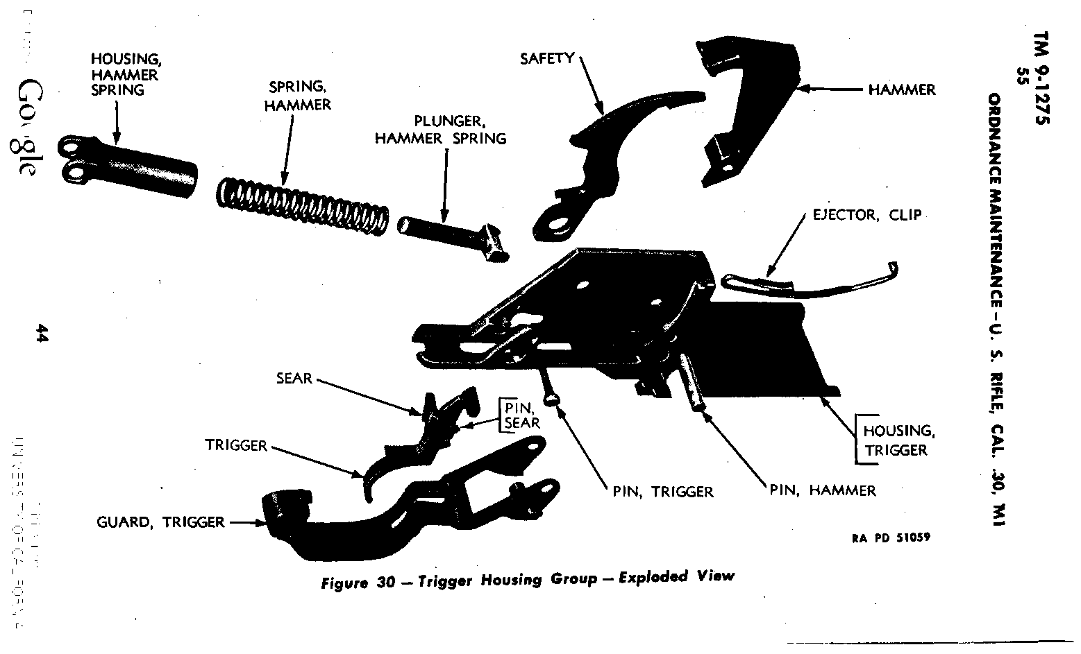
- Trigger housing group: trigger and sear assembly, trigger pin, hammer, hammer pin, hammer spring, hammer spring plunger, hammer spring housing, safety, clip ejector, trigger guard — drift punch
- Barrel and receiver group: op rod spring and follower rod, operating rod, bolt (extractor, extractor spring and plunger, ejector and spring, firing pin), follower and follower arm, follower pin, bullet guide, op rod catch and pin, clip latch, pin and spring, gas cylinder lock screw, gas cylinder lock, gas cylinder, front sight, rear sight (knobs, aperture, cover, base) — M1 combination tool, drift punch
- Stock group: butt plate assembly and screws, rear swivel, front ferrule and swivel, front handguard, rear handguard, clip and band, lower band and pin, stacking swivel
Special tools
- M1 combination tool / M10 cleaning rod handle — Gas cylinder lock screw, rear sight, extractor
- Drift punches (3/32", 1/8") — Trigger, hammer, clip latch, follower arm and op-rod catch pins
- Extractor removing tool (optional) — Removing the bolt parts with the bolt in the receiver (TM 9-1275 para 55)
- Rear handguard / lower band pin punch — Rear handguard band and lower band pin
Known pain points
- Stripping the trigger housing means holding the hammer spring compressed with the thumb on the sear, bracing the housing, and drifting the trigger pin out, then letting the spring out slowly. Going back in is the same fight in reverse. (both)
Source: TM 9-1275 Ordnance Maintenance: U.S. Rifle, Cal. .30, M1 (November 6, 1942), as changed by Changes No. 1 (May 15, 1943), par. 77c — War Department archive.org [3] — “Hold group in right hand with right thumb on sear, forefinger pulling back on trigger base of trigger housing braced against a firm support, and press on sear with right thumb to relieve tension on trigger pin.” - Releasing the bolt's extractor frees the ejector, ejector spring, extractor spring and plunger at once; on reassembly the firing pin and ejector notches have to line up with the extractor spindle before it is pushed home. (both)
Source: TM 9-1275 Ordnance Maintenance: U.S. Rifle, Cal. .30, M1 (November 6, 1942), as changed by Changes No. 1 (May 15, 1943), par. 77c — War Department archive.org [3] — “Place the thumb over the face of the bolt to prevent the ejector, ejector spring, extractor spring and its plunger from flying out when the extractor is released.” - The operating rod is bent on purpose and is easily sprung if forced off or on its track, which ruins function and accuracy. (both)
Source: FM 23-5: U.S. Rifle, Caliber .30, M1 — Department of the Army archive.org [4] — “The operating rod is bent intentionally so that it will not bind against the enlarged portion of the barrel. Do not attempt to straighten it.” - The gas cylinder lock has to come back to alignment by hand, and the gas cylinder splines are easily burred when it is tapped off. (both)
Source: FM 23-5: U.S. Rifle, Caliber .30, M1 — Department of the Army archive.org [4] — “If the lock is not alined with the gas cylinder, do not force it, but unscrew it until it is alined.” - The detail strip beyond the field strip was an ordnance-level job. (both)
Source: TM 9-1275 Ordnance Maintenance: U.S. Rifle, Cal. .30, M1 (November 6, 1942), as changed by Changes No. 1 (May 15, 1943), par. 77c — War Department archive.org [3] — “are to be undertaken only by ordnance personnel to whom such work has been properly delegated.”
See also 4 documented reassembly problems and their fixes.
Fit or check on rebuild
- Rear sight knob tension and zero — The knobs must hold their clicks and the rifle has to be re-zeroed after the sight is off
Source: TM 9-1275 Ordnance Maintenance: U.S. Rifle, Cal. .30, M1 (November 6, 1942), as changed by Changes No. 1 (May 15, 1943), par. 77c — War Department archive.org [3] — “Try the rear sight elevating and windage knobs for tension” - Gas cylinder lock alignment — The lock must come round to alignment by hand without forcing
Source: FM 23-5: U.S. Rifle, Caliber .30, M1 — Department of the Army archive.org [4] — “If the lock is not alined with the gas cylinder, do not force it, but unscrew it until it is alined.” - Trigger function and hammer hooks — Check the safety, trigger pull and that the hammer does not follow; a re-coated sear/hammer face must not be coated
- Stock-to-receiver fit — A refinished stock or coated receiver can make the trigger guard hard to latch or the action loose in the stock
This is Pew-Takedown's rating, not the manufacturer's. How tiers are rated. Forum reports are owners' experience, not specifications.
Procedures
Clear and Make Safe
Clear & Make Safe- Point the muzzle in a safe direction and keep your finger off the trigger.
- Pull the operating rod handle fully to the rear and hold it there. Press the clip latch on the left side of the receiver to eject any en bloc clip.WarningKeep the edge of your hand against the operating rod handle throughout. The bolt will try to close.Removed at this step:
En bloc clip, if present - Lock the bolt back by pressing the follower down while easing the operating rod forward slightly onto the follower's catch.
- Inspect the chamber and receiver with a light and physically confirm the chamber is empty.
- Push the safety — the tab at the front of the trigger guard — rearward into the trigger guard to the safe position.
- Remove all ammunition and clips from the work area.
Field Strip
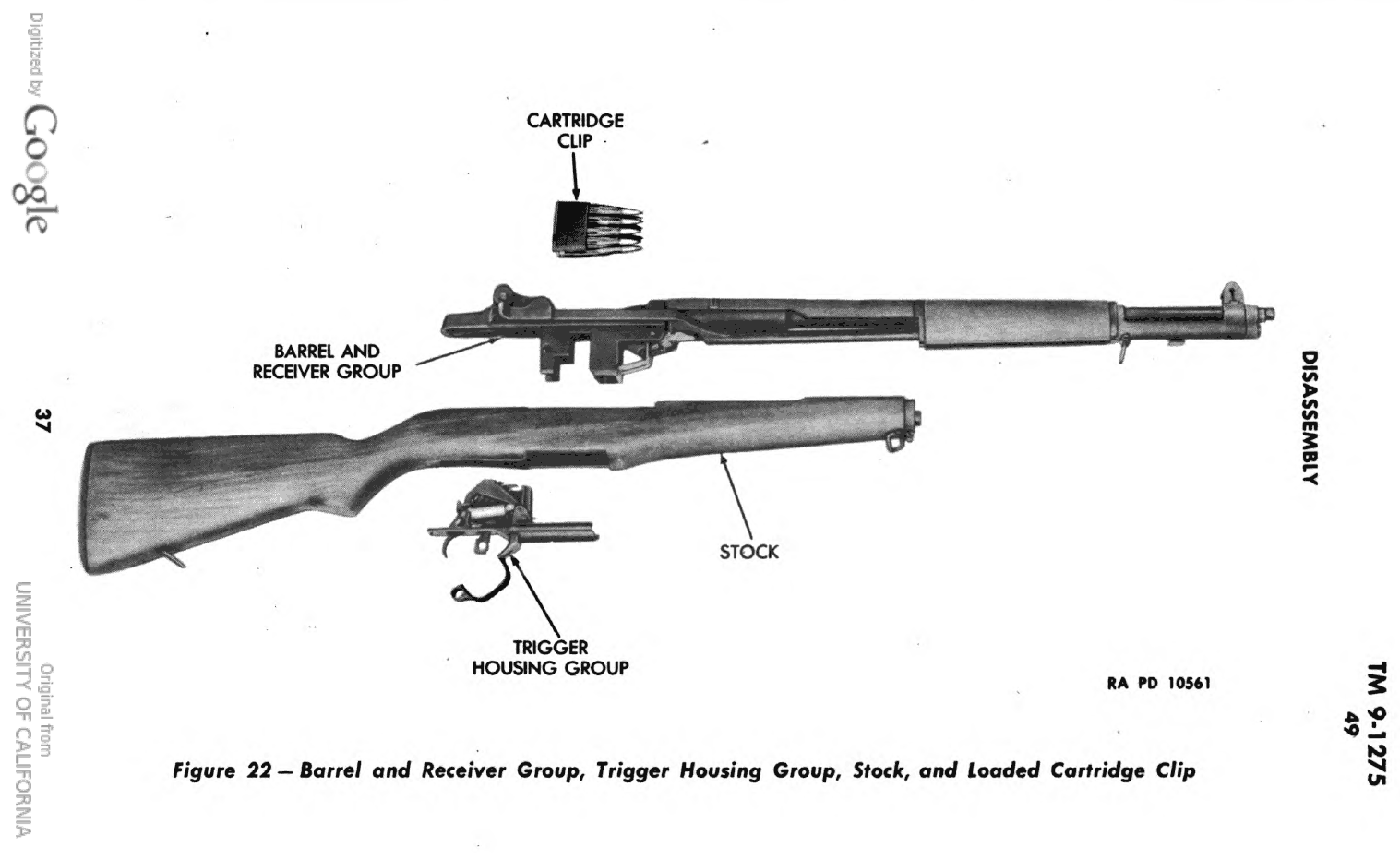
Field StripThree groups: trigger housing, barrel and receiver, and stock.
- Complete the Clear and Make Safe procedure, then let the bolt go forward by depressing the follower with your thumb and allowing the bolt to ride forward over the follower assembly.TipFM 23-5's own method. It avoids the bolt slamming on an empty chamber.
- Place the rifle butt against your left thigh with the sights to the left.
- With the thumb and forefinger of the right hand, pull downward and outward on the REAR of the trigger guard, and swing it out as far as it will go.WarningThe rear of the guard, pulled down and out. Levering the front of it achieves nothing.
- Lift out the trigger housing group.Removed at this step:
Trigger housing group - Lay the rifle on a flat surface with the sights UP and the muzzle to the left. Grasp the rear of the receiver with the left hand and raise the rifle, then give a downward blow with the right hand on the small of the stock.WarningA firm downward blow on the small of the stock is what separates the groups. Tapping the butt does not.Removed at this step:
Stock group - Turn the barrel and receiver group sights DOWN with the rear sight aperture at its lowest position, muzzle to the left.
- Holding the rear of the receiver, grasp the follower rod with the thumb and forefinger of the left hand and disengage it from the follower arm by moving it toward the muzzle.
- Withdraw the follower rod and operating rod spring to the right.WarningDo not separate these two parts. FM 23-5 says so in those words.Removed at this step:
Follower rod and operating rod spring - Pull the operating rod rearward until its lug aligns with the dismount notch in the receiver track, rotate the handle outward and lift the operating rod free.WarningThe operating rod is intentionally bent. Do not attempt to straighten it.Removed at this step:
Operating rod - Turn the barrel and receiver group right side up. Remove the bolt by pulling it forward about one inch, tilting it upward about 15 degrees, then sliding it out forward from the receiver.Removed at this step:
Bolt assembly - Stop here.WarningFM 23-5's disassembly authorization table limits the individual soldier to this level. Bolt, gas cylinder and trigger group internals are armorer or maintenance work.
Disassemble the trigger housing group
Detail Strip tools required gunsmith recommendedStrips the trigger housing group into trigger assembly, hammer spring group, hammer, safety, trigger guard and clip ejector (TM 9-1275 para 56). The sear and sear pin stay in the trigger. TM 9-1275 limits this work to ordnance maintenance personnel (para 47c); under the later TM 9-1005-222-12 (1969) parts replacement in this group is an organizational (unit) level task, not operator level.
Follows TM 9-1275 Ordnance Maintenance: U.S. Rifle, Cal. .30, M1 (November 6, 1942), as changed by Changes No. 1 (May 15, 1943), par. 77c — War Department, para 56, p. 45 archive.org [3]
- With the trigger housing group removed from the rifle, close and latch the trigger guard.
- Release the hammer to the fired position.
- Hold the group in the right hand with the right thumb on the sear and the forefinger pulling back on the trigger, the base of the trigger housing braced against a firm support.
- Press on the sear with the right thumb to relieve tension on the trigger pin.
- Start the trigger pin from its seat with a drift held in the left hand, then remove it.Removed at this step:
Trigger pin - Release the pressure of the right thumb and forefinger gradually, letting the hammer spring extend to its full length while steadying the hammer spring housing with the fingers of the left hand.WarningThe hammer spring is under compression; let it out gradually.
- Remove the trigger assembly.WarningDo not remove the sear pin or sear from the trigger.Removed at this step:
Trigger assembly - Remove the hammer spring housing, hammer spring and hammer spring plunger, and separate these parts.Removed at this step:
Hammer spring housingHammer springHammer spring plunger - Push the hammer pin out from the left side and remove the hammer.Removed at this step:
Hammer pinHammer - Press the top of the safety away from the left side of the trigger housing until its stud snaps out of its seat.
- Lift the safety from its slot in the trigger housing.Removed at this step:
Safety - Slide the trigger guard back to the dismount notch, revolve it slightly counterclockwise and lift it from the housing.Removed at this step:
Trigger guard - Hold a finger over the clip ejector to keep it from flying out of the housing when it is released.
- Insert the point of the combination tool in the dismounting hole in the housing and push the clip ejector out from under the retaining lug.Removed at this step:
Clip ejector
Disassemble the bolt
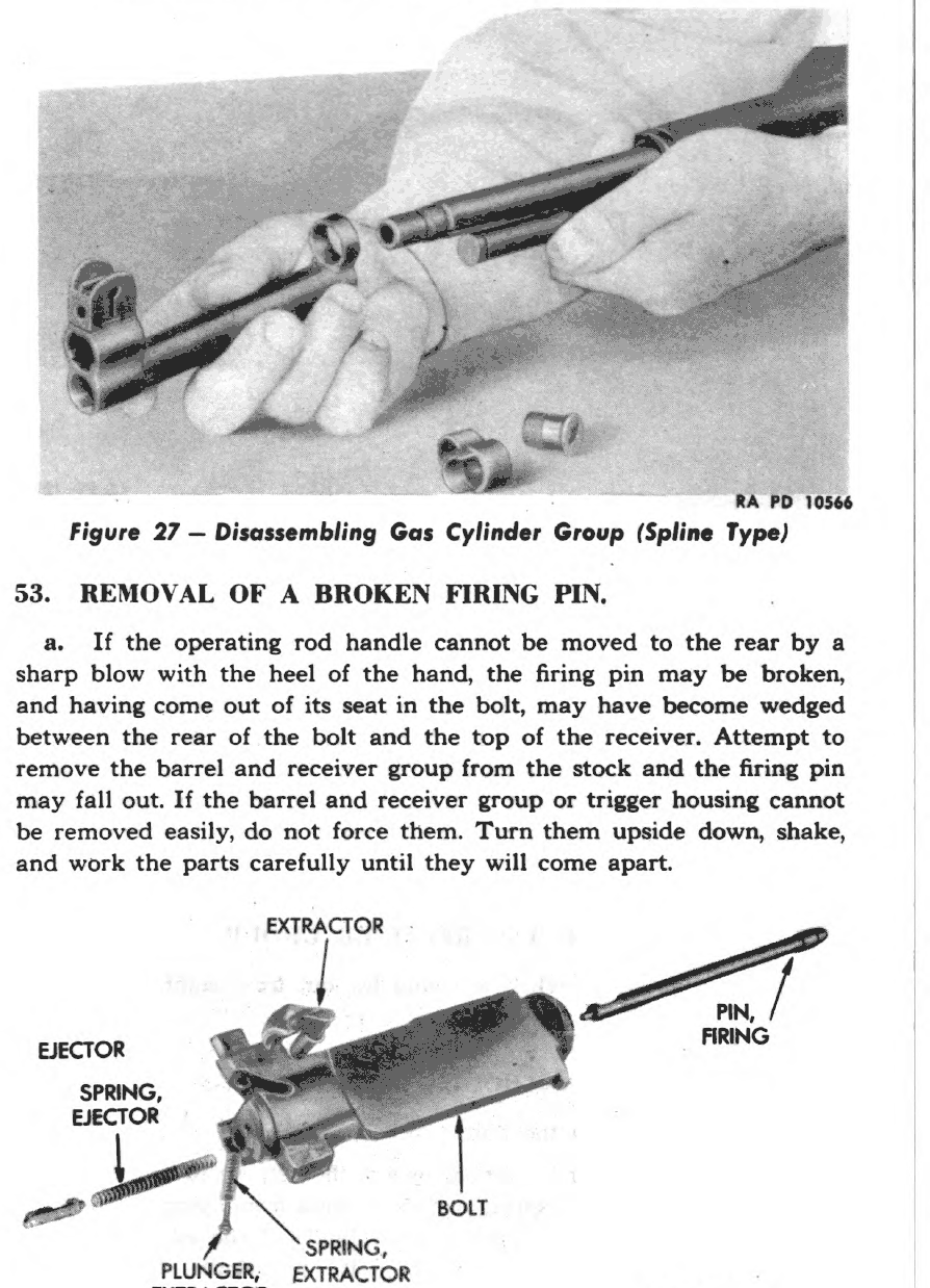
Detail Strip tools required gunsmith recommendedRemoves the extractor, ejector and spring, extractor spring and plunger, and firing pin from the bolt (TM 9-1275 para 52). The extractor spindle retains everything else. TM 9-1275 limits this work to ordnance maintenance personnel (para 47c); under the later TM 9-1005-222-12 (1969) parts replacement in this group is an organizational (unit) level task, not operator level.
Follows TM 9-1275 Ordnance Maintenance: U.S. Rifle, Cal. .30, M1 (November 6, 1942), as changed by Changes No. 1 (May 15, 1943), par. 77c — War Department, para 52, p. 41 archive.org [3]
- Place the thumb over the face of the bolt.WarningThe ejector, ejector spring, extractor spring and its plunger can fly out when the extractor is released.
- Pry the extractor from its seat in the bolt with the screwdriver blade of the combination tool.Removed at this step:
Extractor - Withdraw the ejector and ejector spring from the bolt.Removed at this step:
EjectorEjector spring - Withdraw the extractor spring and plunger from the bolt.Removed at this step:
Extractor springExtractor plunger - Withdraw the firing pin from the bolt.Removed at this step:
Firing pin
Replace the firing pin with the extractor removing tool
Detail Strip tools required gunsmith recommendedReleases the extractor and changes the firing pin with the bolt still in the receiver, using the extractor removing tool (TM 9-1275 para 59a(2)). A special tool issued to ordnance maintenance companies; TM 9-1275 limits this work to ordnance maintenance personnel (para 47c); under the later TM 9-1005-222-12 (1969) parts replacement in this group is an organizational (unit) level task, not operator level.
Follows TM 9-1275 Ordnance Maintenance: U.S. Rifle, Cal. .30, M1 (November 6, 1942), as changed by Changes No. 1 (May 15, 1943), par. 77c — War Department, para 59a(2), pp. 48-49 archive.org [3]
- Retract the bolt and insert the spindle of the extractor removing tool into the chamber until the shoulder of the tool has bearing.
- Allow the bolt to close slowly, turning the ring with the handle so that the lug of the ring is under the extractor.
- Hold the bolt closed against the ring of the tool and turn the ring counterclockwise so that its lug pushes the extractor out of its seat and out of engagement with the ejector.Removed at this step:
Extractor - Retract the bolt slowly, allowing the ejector and extractor plunger springs to release.
- Withdraw the firing pin from its well.Removed at this step:
Firing pin - Assemble the new firing pin from the rear of the receiver.
- Position the pin and ejector so that the extractor spindle will engage their notches before pushing the extractor home.WarningAt no time should undue force be used.
- When the extractor is seated flush in its notch in the bolt, retract the bolt and withdraw the tool from the chamber.
Remove the follower group and clip latch from the receiver
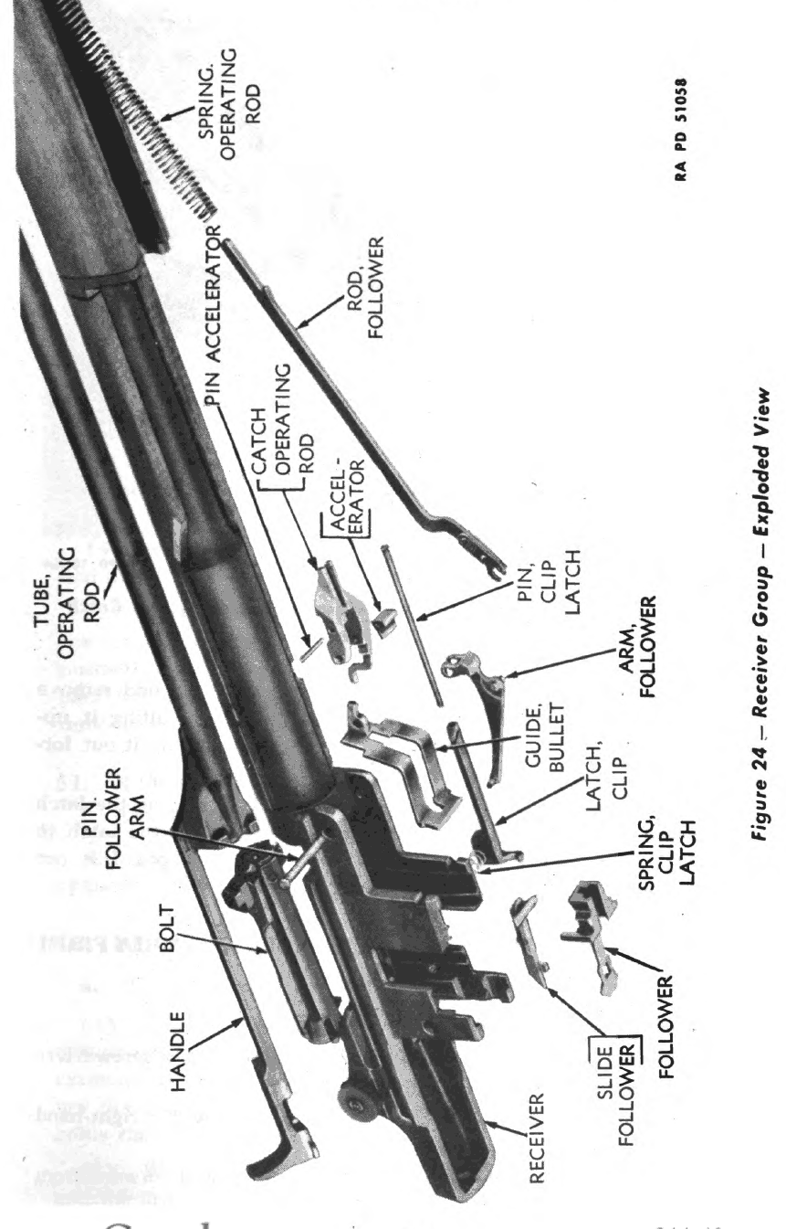
Detail Strip tools required gunsmith recommendedRemoves the follower arm, operating rod catch assembly with accelerator, bullet guide, follower and the clip latch from the receiver (TM 9-1275 para 49a(2), (3) and (6)). In the manual these steps come after the follower rod is unhooked and before the operating rod and bolt come out; the clip latch comes out last. TM 9-1275 limits this work to ordnance maintenance personnel (para 47c); under the later TM 9-1005-222-12 (1969) parts replacement in this group is an organizational (unit) level task, not operator level.
Follows TM 9-1275 Ordnance Maintenance: U.S. Rifle, Cal. .30, M1 (November 6, 1942), as changed by Changes No. 1 (May 15, 1943), par. 77c — War Department, para 49a(2)-(3), p. 36 archive.org [3]
- Complete the Field Strip through removal of the follower rod and operating rod spring, keeping the barrel and receiver group upside down.
- Using the drift of the combination tool, push the follower arm pin out from right to left.Removed at this step:
Follower arm pin - Remove the follower arm, the operating rod catch assembly with its accelerator, and the bullet guide.WarningDo not disassemble the accelerator from the operating rod catch.Removed at this step:
Follower armOperating rod catch assemblyBullet guide - Lift the follower assembly upward and out of its slots in the receiver.Removed at this step:
Follower assembly - Remove the operating rod and the bolt as in the Field Strip.
- Press in on the clip latch to relieve the tension of its spring.
- Drive the latch pin forward out of the receiver with a drift.Removed at this step:
Latch pin - Lift out the clip latch with the clip latch spring attached.Removed at this step:
Clip latchClip latch spring
Remove the gas cylinder, front hand guard, lower band and rear hand guard
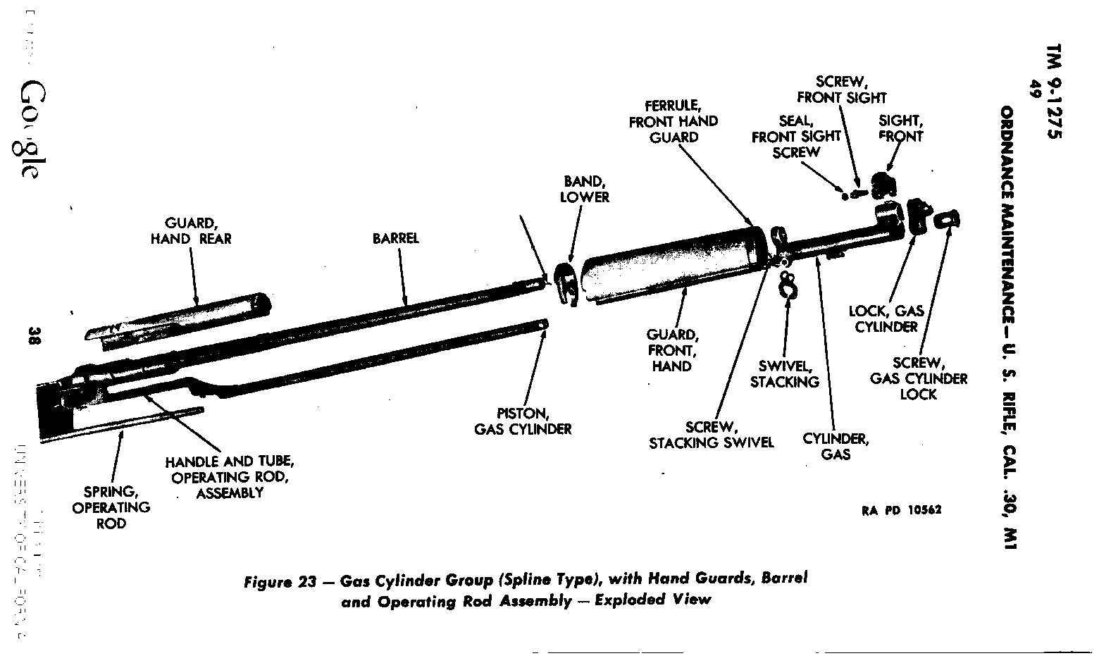
Detail Strip tools required gunsmith recommendedRemoves the spline-type gas cylinder group from the barrel, then the front hand guard, lower band and rear hand guard; also covers the early screw-on gas cylinder (TM 9-1275 paras 50-51). Work on the barrel; TM 9-1275 limits this work to ordnance maintenance personnel (para 47c); under the later TM 9-1005-222-12 (1969) parts replacement in this group is an organizational (unit) level task, not operator level.
Follows TM 9-1275 Ordnance Maintenance: U.S. Rifle, Cal. .30, M1 (November 6, 1942), as changed by Changes No. 1 (May 15, 1943), par. 77c — War Department, para 50, pp. 40-41 archive.org [3]
- Unscrew the gas cylinder lock screw with the screwdriver end of the combination tool or a screwdriver of similar size.Removed at this step:
Gas cylinder lock screw - Unscrew the gas cylinder lock from the end of the barrel.TipThe lock has a right-hand thread.Removed at this step:
Gas cylinder lock - Push or drive the gas cylinder forward off the barrel.Removed at this step:
Gas cylinder - Slide the front hand guard forward off the front end of the barrel.Removed at this step:
Front hand guard - Drive out the pin holding the lower band to the barrel.Removed at this step:
Lower band pin - Slide the lower band forward off the barrel.Removed at this step:
Lower band - Push the rear hand guard forward about one inch so the lip on the right side of its band disengages the slot on the barrel.
- Twist the rear hand guard slightly and lift it from the barrel.Removed at this step:
Rear hand guard - On rifles with the screw-on type gas cylinder, instead remove the front sight screw, lift out the front sight and unscrew the gas cylinder assembly from the barrel.Removed at this step:
Front sight screwFront sightGas cylinder assembly
Disassemble the rear sight
Detail Strip tools required gunsmith recommendedRemoves the rear sight nut, windage knob, elevating knob and pinion, cover, base and aperture from the receiver (TM 9-1275 para 55). TM 9-1275 limits this work to ordnance maintenance personnel (para 47c); under the later TM 9-1005-222-12 (1969) parts replacement in this group is an organizational (unit) level task, not operator level.
Follows TM 9-1275 Ordnance Maintenance: U.S. Rifle, Cal. .30, M1 (November 6, 1942), as changed by Changes No. 1 (May 15, 1943), par. 77c — War Department, para 55, p. 43 archive.org [3]
- Lower the aperture as far as it will go and record the reading on the elevating knob for use in assembling.
- Unscrew the rear sight nut from the right side of the rear sight with the combination tool.Removed at this step:
Rear sight nut - Unscrew the windage knob.WarningTake care that the rear sight nut lock assembly inside the windage knob does not become lost.Removed at this step:
Windage knob - Remove the nut lock and nut lock spring from the windage knob.Removed at this step:
Rear sight nut lockNut lock spring - Remove the rear sight elevating knob screw from the left side of the rear sight with a screwdriver.Removed at this step:
Elevating knob screw - Remove the rear sight elevating knob.Removed at this step:
Elevating knob - Pull the rear sight elevating pinion out from the left side of the receiver.Removed at this step:
Elevating pinion - Grasp the aperture and pull it upward about 1/2 inch.
- Place the thumb under the top of the aperture and push forward to remove the rear sight cover, rear sight base and aperture.Removed at this step:
Rear sight coverRear sight baseAperture
Remove the butt plate, rear swivel and stock ferrule
Detail Strip tools required gunsmith recommendedRemoves the butt plate, rear swivel, stock ferrule swivel and stock ferrule (TM 9-1275 para 57). The manual says these parts are never removed unless they or the stock are to be replaced. TM 9-1275 limits this work to ordnance maintenance personnel (para 47c); under the later TM 9-1005-222-12 (1969) parts replacement in this group is an organizational (unit) level task, not operator level.
Follows TM 9-1275 Ordnance Maintenance: U.S. Rifle, Cal. .30, M1 (November 6, 1942), as changed by Changes No. 1 (May 15, 1943), par. 77c — War Department, para 57, pp. 46-47 archive.org [3]
- Unscrew the wood screw that retains the heel end of the butt plate to the stock.Removed at this step:
Butt plate wood screw - Unscrew the toe screw, the machine screw that threads into the inner end of the rear swivel, and remove the butt plate and swivel.Removed at this step:
Butt plate toe screwButt plateRear swivel - Unscrew the stock ferrule screw and remove the stock ferrule swivel and stock ferrule.WarningThe end of this screw is normally peened over, so the screw must be replaced if removed.Removed at this step:
Stock ferrule screwStock ferrule swivelStock ferrule
Reassemble the trigger housing group
Detail Reassembly tools required gunsmith recommendedReassembles the trigger housing group in the manual's order: clip ejector, trigger guard, safety, hammer, hammer spring group, trigger and trigger pin (TM 9-1275 para 74). TM 9-1275 limits this work to ordnance maintenance personnel (para 47c); under the later TM 9-1005-222-12 (1969) parts replacement in this group is an organizational (unit) level task, not operator level.
Follows TM 9-1275 Ordnance Maintenance: U.S. Rifle, Cal. .30, M1 (November 6, 1942), as changed by Changes No. 1 (May 15, 1943), par. 77c — War Department, para 74, pp. 68-69 archive.org [3]
- Place the clip ejector in the trigger housing with its short arm up, the tip of its long arm in its slot in the vertical front face of the housing, and its loop against its stud on the left side of the housing.
- Hold the trigger housing with its left side down and rear end to the right, holding the loop of the clip ejector against its stud with the right thumb and the long arm up in its slot with the left forefinger.
- Pry the long arm of the clip ejector toward your body, near its left end, with the left thumb to seat it.
- Hold the trigger housing in the left hand, top up and forward end to the front, and the trigger guard in the right hand with its winged section pointing to the left.
- Place the winged sections astride the bottom of the trigger housing with the hammer stop over the safety slot.
- Rotate the trigger guard downward, then slide it forward into position.
- Replace the safety so that its thumbpiece passes through the slot in both the trigger guard and the bottom of the housing and its stud snaps into its seat in the side plate of the trigger housing.
- Push the safety thumbpiece forward to the ready position.
- Insert the hammer loosely in the cocked position and align its pin hole with the pin holes in the trigger housing and trigger guard.
- Insert the hammer pin from the right.
- Swing the hammer to the fired position.
- Place the trigger housing on a smooth surface, base of the housing down and to the left.
- Assemble the hammer spring housing, hammer spring and hammer spring plunger into one unit.
- Place the plunger in its seat against the hammer with the open side of the hammer spring housing toward the safety, and hold the assembled parts in a raised position with the left thumb and forefinger.
- With the right hand insert the trigger into the trigger slot so that the notch at the curved rear surface of the finger piece bears against the rear of the slot in the trigger housing.
- Arrange the parts so that the bottom shoulder of the hammer spring housing rests in the notch just below and forward of the trigger pin hole and the two wings of the hammer spring housing straddle the sear pin.
- Push down with the left thumb on the top of the rear end of the hammer spring housing while pulling the trigger rearward with the right forefinger and pushing forward on the sear with the right thumb, bringing the trigger pin hole into alignment with the holes in the trigger housing.
- Hold this alignment with the right hand, bracing the base of the trigger housing against a firm surface, and insert the trigger pin with the left hand up to its head.
- Hold the trigger housing in the right hand, open side up and top of the hammer toward your body, with the right thumb in rear of the sear and the fingers around the front wall of the housing.TipThe manual calls this the quickest method of seating the trigger pin head and says it works on the newest and stiffest rifle.
- Place the left thumb on the head of the trigger pin, then vigorously close the right hand while pressing down on the pin head to seat it.
Reassemble the bolt
Detail Reassembly tools required gunsmith recommendedReassembles firing pin, ejector, extractor spring and plunger, and extractor using the combination tool to compress the ejector (TM 9-1275 para 76). TM 9-1275 limits this work to ordnance maintenance personnel (para 47c); under the later TM 9-1005-222-12 (1969) parts replacement in this group is an organizational (unit) level task, not operator level.
Follows TM 9-1275 Ordnance Maintenance: U.S. Rifle, Cal. .30, M1 (November 6, 1942), as changed by Changes No. 1 (May 15, 1943), par. 77c — War Department, para 76, p. 71 archive.org [3]
- Insert the firing pin into the bolt, making sure that its tang enters the slot in the rear of the bolt.
- Grasp the bolt in the left hand, top up and extractor recess to the right, holding the firing pin in place with the little finger.
- Insert the ejector with the ejector spring attached.
- Insert the extractor spring and plunger.
- Set the stud of the extractor into its hole in the bolt without forcing it against the ejector spring.
- Place the drift of the combination tool in the left groove of the bolt with the ejector in the ejector cut on the face of the tool.
- Press down on the combination tool to compress the ejector spring and align the ejector.
- With the left thumb push the extractor in until the extractor plunger is seated.WarningThe manual says this operation should be performed only with the combination tool.
Install the clip latch and follower group in the receiver
Detail Reassembly tools required gunsmith recommendedInstalls the clip latch, then (after the bolt and operating rod) the follower slide, follower, bullet guide, operating rod catch and follower arm (TM 9-1275 para 78). TM 9-1275 limits this work to ordnance maintenance personnel (para 47c); under the later TM 9-1005-222-12 (1969) parts replacement in this group is an organizational (unit) level task, not operator level.
Follows TM 9-1275 Ordnance Maintenance: U.S. Rifle, Cal. .30, M1 (November 6, 1942), as changed by Changes No. 1 (May 15, 1943), par. 77c — War Department, para 78, pp. 73-74 archive.org [3]
- Lay the barrel and receiver group on its right side and place the clip latch with its spring in position on the left side of the receiver.
- Insert the latch pin into the receiver from the forward end and locate it in the hole in the forward end of the latch.
- Press lightly on the rear end of the latch to relieve the spring tension and push the pin through the latch into the rear hole in the receiver.
- Install the bolt and operating rod as in the Reassembly procedure, and push them to the closed position.
- If the follower slide has been removed, hook the slide in place in the small end of the follower.
- Stand the two pieces on end or mount them at an angle in a vise, and deliver a sharp blow on the rear end of the slide so it snaps back into position on the follower.
- Place the follower, slide below it and small end to the rear, in the grooved ways in the front pair of lips of the receiver.WarningDo not insert the follower in the rear pair of lips.
- Place the bullet guide on the receiver with the hole in its lip in line with the receiver and the lugs on its opposite end in the corresponding grooves in the receiver lips, so that it projects approximately square from the receiver.WarningDo not insert the guide so that its contour conforms closely to the contour of the receiver.
- Insert the long arm of the operating rod catch, with accelerator, through the clearance slot between the bullet guide and the receiver until the holes in the catch coincide with those in the receiver, with the accelerator above the lug on the bullet guide.TipIn this position the arm of the catch hooks under the lug on the clip latch where it extends through the side of the receiver.
- Insert the long arm of the follower arm through the clearance slot in the center of the bullet guide and into the grooves in the forward end of the follower.
- Drop the front end of the follower arm over the lug on the bullet guide until the holes in the follower coincide with those in the receiver.
- With the receiver group upside down, insert the follower arm pin from left to right through the receiver, bullet guide, operating rod catch assembly and follower.
- Insert the operating rod spring into the operating rod and engage the hooks of the follower rod with the lugs on the follower arm, making sure the hump on the follower rod engages the slot in the operating rod catch.TipWhen correctly in place the follower rod closely parallels the lower edge of the barrel.
Install the gas cylinder group
Detail Reassembly tools required gunsmith recommendedInstalls the spline-type gas cylinder and lock as revised by Changes No. 1 (15 May 1943) to para 77, or the early screw-on type. The manual gives no assembly steps for the lower band and hand guards. TM 9-1275 limits this work to ordnance maintenance personnel (para 47c); under the later TM 9-1005-222-12 (1969) parts replacement in this group is an organizational (unit) level task, not operator level.
Follows TM 9-1275 Ordnance Maintenance: U.S. Rifle, Cal. .30, M1 (November 6, 1942), as changed by Changes No. 1 (May 15, 1943), par. 77c — War Department, para 77, p. 71; para 77b-c as changed by archive.org [3]
- Place the open loop of the gas cylinder over the end of the barrel and slide it on until the splines on the cylinder and barrel are fully engaged.
- Place the gas cylinder lock over the barrel with its lug forward and screw it down as far as possible.WarningDo not force the lock.
- Unscrew the lock a fraction of a turn to the left until the screw hole in the lock lines up with the threaded hole in the gas cylinder.
- Turn the gas cylinder lock screw in several threads with the fingers only.
- Push the gas cylinder lightly toward the muzzle until it rests against the lock.
- Tighten the lock screw so it cannot work loose while firing, to 17 to 20 foot-pounds.TipChanges No. 1 equates this to a pressure of approximately 60 pounds applied to each end of a combination tool.
- On rifles with the screw-on type gas cylinder, instead screw the gas cylinder assembly to the barrel and replace the front sight and front sight screw.
Reassemble the rear sight
Detail Reassembly tools required gunsmith recommendedReassembles the rear sight, zeroes windage, sets nut tension and restores the recorded elevating knob setting (TM 9-1275 para 75). TM 9-1275 limits this work to ordnance maintenance personnel (para 47c); under the later TM 9-1005-222-12 (1969) parts replacement in this group is an organizational (unit) level task, not operator level.
Follows TM 9-1275 Ordnance Maintenance: U.S. Rifle, Cal. .30, M1 (November 6, 1942), as changed by Changes No. 1 (May 15, 1943), par. 77c — War Department, para 75, pp. 69-70 archive.org [3]
- Assemble the rear sight base and cover, inserting the front lip of the cover in its slot at the forward end of the sight bracket.
- Raise the sight base slightly and, with the screwdriver blade of the combination tool held horizontally, press forward on the rear lip of the cover until it snaps into its slot in the rear end of the sight bracket.
- Insert the aperture in the slot opening in the rear sight base and slide it to its extreme forward position.
- Holding the rear sight base forward against the cover, insert the elevating pinion through the left side of the receiver so that it meshes with the rack on the aperture.
- Move the rear sight base to the left.
- Insert the windage knob through the right side of the receiver and screw it into the rear sight until the ZERO mark on the base registers with the center line of the windage scale on the receiver.
- Place the rear sight nut lock spring and nut lock in the windage knob around the threaded end of the elevating pinion, flange of the nut lock outside and its flat aligned with the flat cut on the pinion.
- Holding the elevating drum, screw the rear sight nut onto the elevating pinion with the combination tool until the desired tension on both the elevating drum and windage knob is obtained.WarningIf the nut is screwed too tight, the knobs become locked and cannot be turned.
- Lower the aperture as far as it will go by turning the elevating pinion.
- Replace the elevating knob and rotate it to the position noted before disassembly.
- Holding it in this position, replace the elevating knob screw and tighten it.
- Run the aperture as high as possible and complete the tightening of the screw.
Install the butt plate, rear swivel and stock ferrule
Detail Reassembly tools required gunsmith recommendedReinstalls the butt plate and rear swivel and, with a new screw, the stock ferrule and swivel (TM 9-1275 para 73). TM 9-1275 limits this work to ordnance maintenance personnel (para 47c); under the later TM 9-1005-222-12 (1969) parts replacement in this group is an organizational (unit) level task, not operator level.
Follows TM 9-1275 Ordnance Maintenance: U.S. Rifle, Cal. .30, M1 (November 6, 1942), as changed by Changes No. 1 (May 15, 1943), par. 77c — War Department, para 73, p. 68 archive.org [3]
- Insert the rear swivel in the slot in the stock.
- Insert the wood screw that retains the heel end of the butt plate to the stock.
- Insert and tighten the toe screw, bringing the rear swivel into alignment so the screw threads into it.
- Assemble the stock ferrule and stock ferrule swivel to the stock with a new stock ferrule screw.
- Peen over the end of the stock ferrule screw to prevent its coming loose in service.
Reassembly
Reassembly- Set the bolt into the receiver, engaging its lugs in the raceway, and slide it forward.
- Engage the operating rod's lug at the dismount notch, rotate it into the track, and slide it forward, seating the piston into the gas cylinder.
- Insert the operating rod spring and follower rod into the operating rod, compress them, and engage the follower rod with the follower arm.WarningKeep the spring under control throughout.
- Set the barrel and receiver group into the stock, aligning it fully forward.
- Set the trigger housing group into the stock and receiver, then swing the trigger guard closed and latch it fully.WarningIf the trigger guard will not close, the trigger housing is not aligned. Do not force it — the housing can crack the stock.
- Cycle the action several times and perform the function check.
Diagrams
public domainThese are reproduced from government technical manuals, which are not subject to copyright. Manufacturer manual diagrams are not reproduced here — the entry links to the manual instead.
Torque specifications
| Fastener | Torque | Sequence, notes and the source's words | Where it comes from |
|---|---|---|---|
| Gas cylinder lock screw U.S. Rifle, Cal. .30, M1 (spline-type gas cylinder group) |
17–20 ft-lb 23–27.1 N·m · 204–240 in-lb |
Par. 77 Assembly of gas cylinder group (spline type), as changed by C1: b. Place the gas cylinder lock over the barrel with the lug forward and screw into position: (1) Screw lock down as far as possible. Do not force. (2) Unscrew lock a fraction of a turn to the left until the screw hole in the lock lines up with the threaded hole in the gas cylinder. (3) Turn screw in several threads with the fingers only. (4) Push the gas cylinder lightly toward the muzzle until it rests against the lock. c. Tighten the lockscrew so it cannot work loose while firing (17 to 20 foot pounds). “Tighten the lockscrew so it cannot work loose while firing. A torque of 17 to 20 foot pounds” |
TM 9-1275 Ordnance Maintenance: U.S. Rifle, Cal. .30, M1 (November 6, 1942), as changed by Changes No. 1 (May 15, 1943), par. 77c — War Department, p. C1, p. 1 (PDF p. 11) archive.org [3] |
Function check
- Verify the rifle is unloaded before each step.
- Cycle the operating rod and confirm the bolt locks and unlocks smoothly.
- With the hammer cocked, engage the safety and press the trigger. The hammer must not fall.
- Disengage the safety and press the trigger. The hammer should fall.
- Hold the trigger back, cycle the action, and release the trigger to feel the reset.
- Insert an empty en bloc clip and confirm it latches and the clip latch ejects it.
- Confirm the trigger guard is fully latched and the rifle sits tight in the stock.
Maintenance
Lubrication points
- Bolt lugs and camming surfaces
- Operating rod track and its camming lug
- Operating rod piston (light film only)
- Receiver rails
- Hammer hooks and sear
Cleaning notes
The M1 is traditionally run with grease rather than oil on the bearing surfaces — bolt lugs, the operating rod cam, and receiver rails. Do not grease the gas cylinder or piston heavily. After corrosive ammunition, flush with water-based solvent the same day.
Suggested inspection interval: roughly every 500 rounds. This is a general guideline, not a manufacturer specification.
Wear parts to inspect
Operating rod (inspect for bends) · Op rod spring · Extractor and ejector · Bolt lugs · Gas cylinder lock screw tightness
Common issues
| Symptom | Likely cause | What to do |
|---|---|---|
| Broken or badly bruised thumb while loading | Garand thumb — the bolt closing on the hand | Keep the edge of the loading hand pressed against the operating rod handle while seating a clip. Practice the motion with an empty clip first. |
| Bent operating rod | Overpressure commercial ammunition, or the rod being sprung during disassembly | A bent rod must be replaced or straightened by a specialist. Use appropriate ammunition or an adjustable gas plug. see a gunsmith |
| Failure to eject the clip, or premature clip ejection | Worn clip latch or a damaged clip | Try known-good clips first, then inspect the clip latch and its spring. |
Also covers
The procedures above are reported to apply to: M1 Garand (all manufacturers: Springfield Armory, Winchester, H&R, IHC) · Italian Beretta-made M1 Garands. Verify against the manual for your specific model.
Similar manual of arms
Sourcing
- Confidence
- high — Cross-checked against a primary source such as the manufacturer's manual or an issuing military technical manual.
- Verification
- Checked against an armorer/technical manual
- Last updated
- 2026-10-29
References
Every source this page draws on, with its web address so you can read it yourself. Numbers in brackets elsewhere on the page point here.
- [1] FM 23-5: U.S. Rifle, Caliber .30, M1 — Headquarters, Department of the Army military technical manual primary source
https://archive.org/details/Fm23-5 (checked 2026-09-15) - [2] TM 9-1005-222-12: Rifle, Caliber .30, M1 — U.S. Department of the Army military technical manual primary source
- [3] TM 9-1275 Ordnance Maintenance: U.S. Rifle, Cal. .30, M1 (November 6, 1942), as changed by Changes No. 1 (May 15, 1943), par. 77c — War Department (1942) military technical manual primary source
https://archive.org/download/1942TM9-1275/1942TM9-1275.pdf (checked 2026-09-27) - [4] FM 23-5: U.S. Rifle, Caliber .30, M1 — Department of the Army military technical manual primary source
https://archive.org/download/Fm23-5/Fm23-5.pdf (checked 2026-10-29) - [5] U.S. Rifle, Caliber .30, M1 (owner's manual, Civilian Marksmanship Program; (c) 1997 Xanagraf LLC) - Parts Legend / Exploded View — Civilian Marksmanship Program (Corporation for the Promotion of Rifle Practice and Firearms Safety) / Xanagraf LLC website secondary source
https://archive.org/download/gunmanual_Cmp_M1_Garand/Cmp%20M1%20Garand_djvu.txt (checked 2026-10-29)
Notes: Most surviving M1 rifles have been arsenal rebuilt with mixed-manufacturer parts. Headspace should be verified by a gunsmith on any rifle of unknown history. Re-read on 2026-09-15 against FM 23-5 (1965), which is now cited by URL. The procedure was already close; three things were corrected or added from the manual. Separating the stock group is a downward blow on the small of the stock with the rifle raised by the rear of the receiver, sights up and muzzle left — not tapping the butt. The follower rod and operating rod spring are withdrawn to the right as one unit, and FM 23-5 states plainly that they are not to be separated. The FM's own method for letting the bolt down is to depress the follower and let the bolt ride forward over it. The manual's disassembly authorization table also limits the individual soldier to this level, which is now reflected in the stopping point. Field-strip bolt removal corrected on 2026-10-03 against TM 9-1275 para 49a(5): the bolt comes out forward, tilted up about 15 degrees — not rearward, as the previous version said.