← All firearms · Printable work order
M14 / Springfield M1A
- moderate
- Shop tier 3
- high confidence
- Rifle
- battle rifle
- short stroke piston
- garand derived
- service rifle
field strip ~5 min · reassembly ~8 min · detail strip ~45 min
Specifications
- Manufacturer
- Springfield Armory, Inc.
- Origin
- United States
- Category
- Rifle
- Action
- Gas, short-stroke piston
- Calibers
- 7.62x51mm NATO, .308 Winchester
- Capacity
- 20+1 with the standard magazine
- Production
- 1959–present (in-production)
- Also known as
- M14, M1A, M14 rifle, 7.62mm
Model-specific safety
- The magazine rocks in and out rather than inserting straight up. Do not force it.
- The operating rod spring is long and under substantial tension. Ease it out under control rather than letting it fly.
- Do not disturb the gas cylinder, gas cylinder lock, or the castle nut during routine maintenance. They are torqued to a specification and moving them changes the rifle's zero and can affect accuracy badly.
- The gas system is a self-regulating short-stroke design and does not need routine disassembly. Do not scrub the gas piston bright — a light carbon film is normal and desirable.
- Stock fit matters on this rifle. Removing and refitting the action can shift zero if the bedding is disturbed.
Under spring tension
- Operating rod spring
- Hammer spring in the trigger group
- Magazine spring
Easily lost parts
Connector lock · Operating rod spring guide · Trigger group · Bolt roller
Tools
| Tool | Required | Used for | Substitute |
|---|---|---|---|
| Combination tool or a screwdriver | Optional | Gas cylinder lock and castle nut work, which is beyond a field strip. |
Shop difficulty
Shop tier 3 Tier 3 — hardest among rifles and carbines, for the full job: strip to the parts that get coated and put it back together working. There are 62 key numbers, and the trigger housing works the same way as the Garand's, with the hammer spring held compressed. The op rod spring is under heavy load and Springfield calls removing it dangerous. The bolt needs a special tool, and the gas cylinder, front sight and flash suppressor all come off with set screws and a castle nut that has to be re-timed.
Parts: 62 numbered parts (Springfield M1A Standard, complete rifle with stock; trigger & sear as an assembly; bolt broken down), from M1A Operation & Safety Manual — Springfield Armory, Inc., p. 33 springfield-armory.com [1].
Bench time: about 60 min to strip, 90 min to rebuild (estimate). Estimate: field strip plus trigger housing, bolt (with tool), op rod/spring/guide, connector lock, bolt stop, gas cylinder/piston/plug/lock, flash suppressor and front sight, rear sight, stock hardware. Rebuild longer for the trigger housing springs, the gas system, the flash suppressor alignment and the function check.
Small parts: 10 pins, 9 springs, 2 detents or plungers (counted from the manufacturer's parts list (one per key number unless a quantity is given))
What comes off for coating
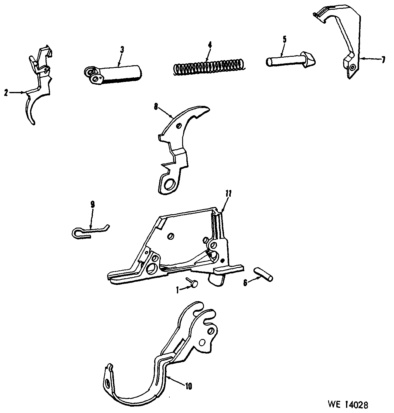
- Trigger housing group: trigger & sear assembly, trigger pin, hammer, hammer pin, hammer spring, plunger and housing, safety and safety spring, magazine catch, spring and pin, trigger guard — drift punch
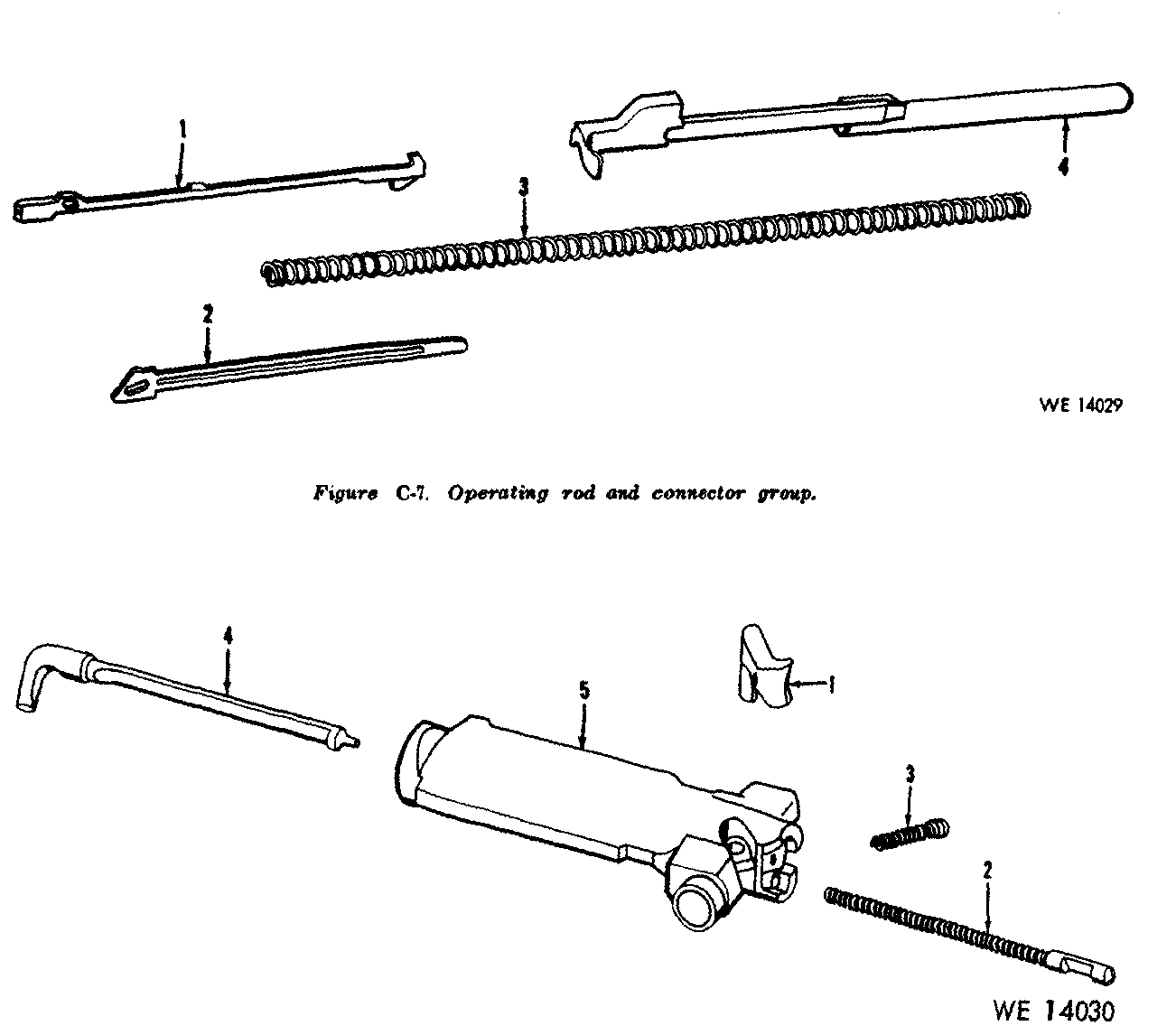
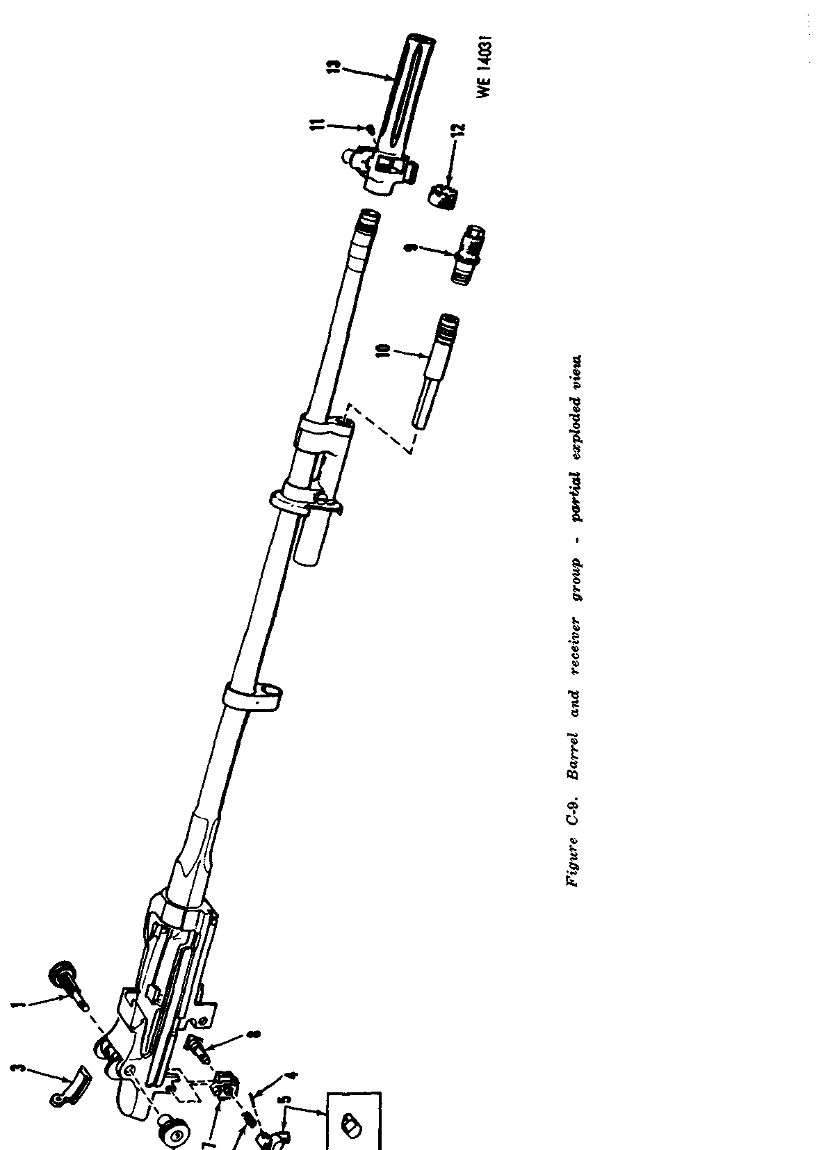
- Barreled receiver: op rod spring and guide, connector lock and pin, operating rod, bolt (roller, firing pin, extractor, spring, plunger, ejector, spring), bolt stop, pin and spring, clip guide and pin, op rod guide and pin, gas cylinder plug, piston, cylinder lock, gas cylinder, spindle valve, pin and spring, flash suppressor, castle nut and set screw, front sight and set screw, rear sight (knobs, aperture, cover, base) — M1A/M14 bolt tool, gas cylinder plug wrench, castle nut wrench
- Stock group: butt plate assembly and screws, rear swivel, stock liner screw, front ferrule and swivel, handguard and clip
Special tools
- M14/M1A bolt disassembly tool — Firing pin and extractor removal and reassembly
- Gas cylinder plug wrench / combination tool — Gas cylinder plug
- Castle nut / flash suppressor wrench — Removing the flash suppressor and front sight
- Drift punches incl. 3/32" and 5/64" pin punches — Clip guide, bolt stop, connector lock, op rod guide and spindle valve pins
Known pain points
- The op rod spring and guide come out under heavy compression once the connector lock is slid over, and can launch the guide. (both)
Source: M1A Operation & Safety Manual — Springfield Armory, Inc. springfield-armory.com [1] — “Warning: Removing the operating rod spring is a dangerous procedure. If not properly held, the spring will eject the operating spring guide and could injure you or a bystander.” - Springfield says the bolt is not to be stripped without a special reassembly tool (the roller, firing pin, extractor and ejector come out of it). (both)
Source: M1A Operation & Safety Manual — Springfield Armory, Inc. springfield-armory.com [1] — “To disassemble the bolt requires a special re-assembly tool.” - The gas piston must sit below the cylinder threads before the plug goes in, and the piston is run dry. A misassembled gas system short-strokes or binds. (reassembly)
Source: M1A Operation & Safety Manual — Springfield Armory, Inc. springfield-armory.com [1] — “Make sure the piston is completely below the threads in the gas cylinder before replacing plug.” - Glass-bedded (NM/Super Match) actions must be knocked out of the stock and lose bedding fit every time they come apart. (disassembly)
Source: M1A Operation & Safety Manual — Springfield Armory, Inc. springfield-armory.com [1] — “Unnecessary removal promotes wear, sloppy fit, inaccuracy and defeats the purpose of the bedding.”
Fit or check on rebuild
- Flash suppressor/front sight alignment — The suppressor is clamped by the castle nut and set screw and must be re-aligned to the bore line and front sight; the rifle needs a re-zero
- Gas piston and plug — Piston below the threads, plug torqued, run dry
Source: M1A Operation & Safety Manual — Springfield Armory, Inc. springfield-armory.com [1] — “Make sure the piston is completely below the threads in the gas cylinder before replacing plug.” - Bedding/stock fit on match rifles — Bedding fit is lost by repeated disassembly
Source: M1A Operation & Safety Manual — Springfield Armory, Inc. springfield-armory.com [1] — “Unnecessary removal promotes wear, sloppy fit, inaccuracy and defeats the purpose of the bedding.” - Trigger function — Hammer must not follow; safety must block
This is Pew-Takedown's rating, not the manufacturer's. How tiers are rated. Forum reports are owners' experience, not specifications.
Manufacturer videos
Official videos from Springfield Armory, Inc.'s own channels, linked rather than copied. Where a video and the steps on this page differ, follow the manufacturer's manual and video.
- Springfield Armory® Workbench: M1A SPRINGFIELD ARMORY
cleaning, maintenance · 2021-01-05
Covers: Springfield Armory M1A (civilian M14-pattern rifle); not the military M14
Procedures
Clear and Make Safe
Clear & Make Safe- Point the muzzle in a safe direction and keep your finger off the trigger.
- Press the magazine release and rock the magazine forward and out.Removed at this step:
Magazine - Pull the operating rod handle fully to the rear and lock the bolt open with the bolt lock.
- Inspect the chamber and magazine well with a light and physically confirm the chamber is empty.
- Push the safety — the tab at the front of the trigger guard — rearward into the trigger guard, and remove all ammunition from the work area.
Field Strip
Field StripThree groups, much like the M1 Garand it descends from.
- Complete the Clear and Make Safe procedure. Put the safety on and remove the magazine before you begin.
- Close the bolt: pull back on the operating rod handle and let the bolt run forward.
- Place the rifle upside down with the barrel pointing away from you. Grasp the fore-end with your left hand, grasp the rear of the trigger guard with the thumb and forefinger of your right hand, and pull upward and outward until the mechanism releases. Lift out the trigger housing group.Removed at this step:
Trigger housing group - To separate the barrelled receiver from the stock, lay the rifle on a flat surface with the sights down and the muzzle to the left. Grip the top of the fore-end grip with your left hand, grasp the rear sight and receiver with your right, and pull down.TipOn a standard rifle the stock separates easily. On a match rifle, or a stubborn one, raise the buttstock and strike down firmly against a hard surface on the stock's cheek surface while pulling the receiver down.Removed at this step:
Stock group - Place the barrel and receiver group on a flat surface, sights down, muzzle to the left. With your left hand pull the operating rod spring and spring guide toward the muzzle to relieve pressure on the connector lock, and with your right forefinger slide the connector lock toward the operating rod handle side of the rifle.WarningThis is the dangerous step. If the spring is not properly held it will eject the spring guide hard enough to injure you or a bystander. Wear eye protection.
- Let the operating rod spring expand slowly, then disconnect and remove the spring and spring guide and separate the two parts.Removed at this step:
Operating rod springOperating rod spring guide - Turn the group so the sights are up and the muzzle points away from you. Pull the operating rod handle back until the guide lug on its inside surface aligns with the disassembly notch on the right side of the receiver. Rotate the operating rod upward and outward, then pull it to the rear to disengage it from the operating rod guide.Removed at this step:
Operating rod - Grasp the bolt by its roller and, while sliding it forward, lift it upward and outward to the right front with a slight counter-clockwise rotating motion.Removed at this step:
Bolt - Stop here. The manual is explicit that disassembly frequency should be kept to a minimum, and asks you not to field strip a match rifle at all unless it is absolutely necessary — the glass bedding is what the accuracy depends on.
Disassemble the firing mechanism
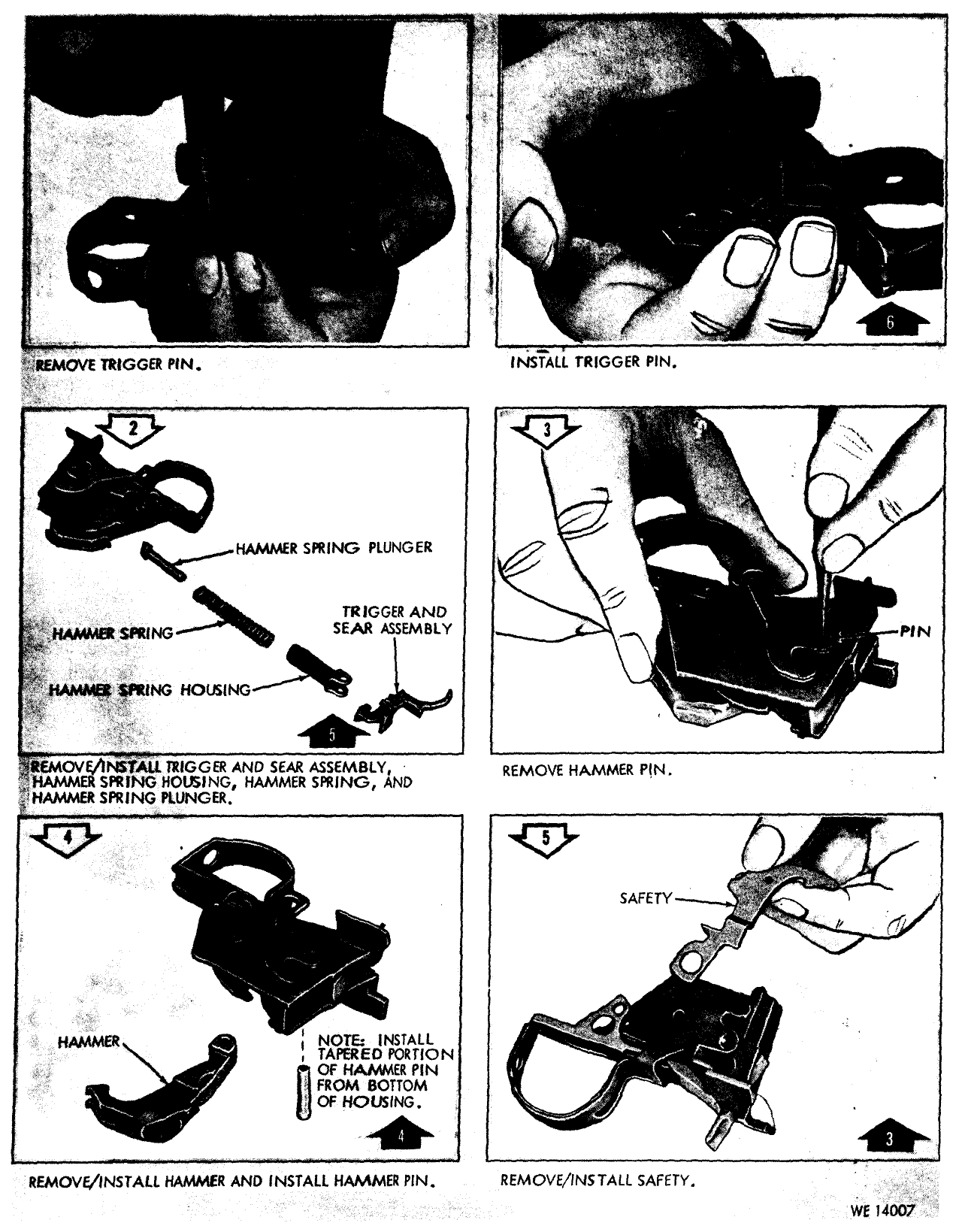
Detail Strip tools required gunsmith recommendedStrips the firing mechanism (trigger housing group) in the order of the numbered disassembly arrows in TM 9-1005-223-20 figs. 3-7 and 3-8: trigger pin, trigger and sear assembly with hammer spring group, hammer pin, hammer, safety, then trigger guard and safety spring. The manual gives only figure captions, no hand positions. TM 9-1005-223-20 places this disassembly at organizational (unit armorer) maintenance (para 3-15); FM 23-8 Chart I and its note to para 16 say the individual soldier will not disassemble the bolt, rear sight or firing mechanism.
Follows TM 9-1005-223-20, Organizational Maintenance Manual, Rifles, 7.62-MM, M14 and M14A1, and Bipod, Rifle, M2 (19 May 1967), archive.org item TM9-1005-223-20 — Headquarters, Department of the Army, para 3-16, p. 3-13; figs. 3-7 and 3-8, p archive.org [2]
- Remove the trigger pin.Removed at this step:
Trigger pin - Remove the trigger and sear assembly, hammer spring housing, hammer spring and hammer spring plunger.Removed at this step:
Trigger and sear assemblyHammer spring housingHammer springHammer spring plunger - Remove the hammer pin.Removed at this step:
Hammer pin - Remove the hammer.Removed at this step:
Hammer - Remove the safety.Removed at this step:
Safety - Remove the trigger guard and safety spring.Removed at this step:
Trigger guardSafety spring
Disassemble the bolt
Detail Strip tools required gunsmith recommendedRemoves the extractor with the combination tool, then the extractor spring and plunger, ejector and firing pin (TM 9-1005-223-20 fig. 3-9). The bolt roller is not removed at this level. TM 9-1005-223-20 places this disassembly at organizational (unit armorer) maintenance (para 3-15); FM 23-8 Chart I and its note to para 16 say the individual soldier will not disassemble the bolt, rear sight or firing mechanism.
Follows TM 9-1005-223-20, Organizational Maintenance Manual, Rifles, 7.62-MM, M14 and M14A1, and Bipod, Rifle, M2 (19 May 1967), archive.org item TM9-1005-223-20 — Headquarters, Department of the Army, para 3-19 and fig. 3-9, p. 3-15 archive.org [2]
- Remove the cartridge extractor from the bolt with the combination tool.Removed at this step:
Extractor - Remove the extractor spring and plunger, the ejector and the firing pin from the bolt.Removed at this step:
Extractor spring and plungerEjectorFiring pin
Disassemble the rear sight
Detail Strip tools required gunsmith recommendedRemoves the windage knob retaining nut, windage knob and pinion assembly, and the aperture, base and cover (TM 9-1005-223-20 fig. 3-10, steps 1-4). The same figure goes on to remove selector parts, which are left out here. TM 9-1005-223-20 places this disassembly at organizational (unit armorer) maintenance (para 3-15); FM 23-8 Chart I and its note to para 16 say the individual soldier will not disassemble the bolt, rear sight or firing mechanism.
Follows TM 9-1005-223-20, Organizational Maintenance Manual, Rifles, 7.62-MM, M14 and M14A1, and Bipod, Rifle, M2 (19 May 1967), archive.org item TM9-1005-223-20 — Headquarters, Department of the Army, para 3-20 and fig. 3-10, p. 3-16 archive.org [2]
- Run the aperture all the way down and record the reading for use when assembling.
- Loosen the windage knob retaining nut.
- Remove the windage knob and pinion assembly.Removed at this step:
Windage knobPinion assembly - Push upward on the aperture to release the cover, and remove the rear sight components.
- Separate the sight aperture, rear sight base and rear sight cover.Removed at this step:
Sight apertureRear sight baseRear sight cover
Disassemble the gas system and remove the handguard
Detail Strip tools requiredRemoves the gas cylinder plug and gas piston, slides the gas cylinder lock and cylinder forward, and removes the front band and handguard (FM 23-8 para 11). FM 23-8 teaches this to the individual soldier; it says the gas cylinder should not be disassembled under normal usage as long as the piston slides freely when the barrel is tilted end for end with the bolt locked to the rear.
Follows FM 23-8 U.S. Rifle 7.62MM, M14 and M14E2 — Headquarters, Department of the Army, para 11, p. 13 archive.org [4]
- Loosen and remove the gas cylinder plug with the wrench of the combination tool.WarningTM 9-1005-223-20 fig. 3-11 cautions: when loosening or tightening the gas cylinder plug, do not hold the rifle with a hand on the hand guards.Removed at this step:
Gas cylinder plug - Tilt the muzzle down and remove the gas piston from the gas cylinder.Removed at this step:
Gas piston - Unscrew the gas cylinder lock.
- Slide the lock and cylinder forward so that the gas port is exposed.
- Slip the front band forward toward the front sight.
- Push the handguard toward the front sight and lift it from the barrel.Removed at this step:
Handguard
Disassemble the magazine
Detail Strip tools requiredRemoves the magazine base, spring and follower (FM 23-8 para 15). Individual soldier level (FM 23-8 Chart I).
Follows FM 23-8 U.S. Rifle 7.62MM, M14 and M14E2 — Headquarters, Department of the Army, para 15, p. 14 archive.org [4]
- Use a pointed object to raise the rear of the magazine base until the indentation on the base is clear of the magazine.
- Grasp the magazine with either hand, with one finger of that hand covering the base.WarningThe spring is under tension; keep a finger over the base.
- Remove the base.Removed at this step:
Magazine base - Guide the spring out one coil at a time to clear the retaining lips of the magazine.
- Remove the magazine spring and follower and separate them.Removed at this step:
Magazine springMagazine follower
Reassemble the firing mechanism
Detail Reassembly tools required gunsmith recommendedReassembles the firing mechanism in the order of the numbered assembly arrows in TM 9-1005-223-20 figs. 3-7 and 3-8, the reverse of disassembly, with the manual's notes on the safety spring and the hammer pin. TM 9-1005-223-20 places this disassembly at organizational (unit armorer) maintenance (para 3-15); FM 23-8 Chart I and its note to para 16 say the individual soldier will not disassemble the bolt, rear sight or firing mechanism.
Follows TM 9-1005-223-20, Organizational Maintenance Manual, Rifles, 7.62-MM, M14 and M14A1, and Bipod, Rifle, M2 (19 May 1967), archive.org item TM9-1005-223-20 — Headquarters, Department of the Army, p. figs. 3-8 and 3-7, pp. 3-15 and 3-14 archive.org [2]
- Install the trigger guard and safety spring, inserting the safety spring at a 90-degree angle and then rotating it down.
- Check that the safety spring sits in the position shown in figure 3-8 after installation.
- Install the safety.
- Install the hammer and install the hammer pin with the tapered portion of the pin entering from the bottom of the housing.
- Install the trigger and sear assembly, hammer spring housing, hammer spring and hammer spring plunger.
- Install the trigger pin.
Reassemble the bolt
Detail Reassembly tools required gunsmith recommendedInstalls the firing pin, ejector and extractor spring and plunger, then seats the extractor with the combination tool (TM 9-1005-223-20 fig. 3-9). TM 9-1005-223-20 places this disassembly at organizational (unit armorer) maintenance (para 3-15); FM 23-8 Chart I and its note to para 16 say the individual soldier will not disassemble the bolt, rear sight or firing mechanism.
Follows TM 9-1005-223-20, Organizational Maintenance Manual, Rifles, 7.62-MM, M14 and M14A1, and Bipod, Rifle, M2 (19 May 1967), archive.org item TM9-1005-223-20 — Headquarters, Department of the Army, p. fig. 3-9, p. 3-15 archive.org [2]
- Install the firing pin, ejector, and extractor spring and plunger in the bolt.
- Place the extractor in position and align the flat recess in the face of the combination tool with the end of the ejector.
- Press in on the ejector and at the same time push down on the extractor, securing all parts within the bolt.
Reassemble the rear sight
Detail Reassembly tools required gunsmith recommendedReassembles the aperture, base and cover, installs them, then the windage knob and pinion assembly and the retaining nut (TM 9-1005-223-20 fig. 3-10, assembly arrows 5-8). TM 9-1005-223-20 places this disassembly at organizational (unit armorer) maintenance (para 3-15); FM 23-8 Chart I and its note to para 16 say the individual soldier will not disassemble the bolt, rear sight or firing mechanism.
Follows TM 9-1005-223-20, Organizational Maintenance Manual, Rifles, 7.62-MM, M14 and M14A1, and Bipod, Rifle, M2 (19 May 1967), archive.org item TM9-1005-223-20 — Headquarters, Department of the Army, p. fig. 3-10, p. 3-16 archive.org [2]
- Assemble the sight aperture, rear sight base and rear sight cover.
- Install the rear sight components on the receiver.
- Push downward on the base to secure the cover, then snap the front.
- Install the windage knob and pinion assembly.TipUse the elevation reading recorded at disassembly.
- Tighten the windage knob retaining nut.
Install the handguard and reassemble the gas system
Detail Reassembly tools requiredInstalls the handguard and front band, then sets the gas cylinder lock, gas piston and gas cylinder plug (FM 23-8 para 12). Individual soldier level.
Follows FM 23-8 U.S. Rifle 7.62MM, M14 and M14E2 — Headquarters, Department of the Army, para 12, pp. 13-14 archive.org [4]
- Place the rifle on a flat surface, sights up and muzzle to the right.
- Engage the ends of the band on the handguard with the front (muzzle) end of the slots on the rear of the barrel and slide the handguard rearward.WarningDo not snap or force the handguard into its installed position.
- Replace the front band.
- Slide the gas cylinder rearward through the front band.
- Tighten the gas cylinder lock by hand to its fully assembled position, then back it off until the loop is aligned with the gas cylinder.
- Replace the gas piston with the flat part toward the barrel and the open end toward the muzzle.WarningTM 9-1005-223-20 fig. 3-11: make certain the gas cylinder, piston and plug are thoroughly dried before installing the piston.TipWhen properly seated the piston protrudes one and one-half inches below the gas cylinder.
- Replace the gas cylinder plug and tighten it securely with the wrench of the combination tool.
Reassemble the magazine
Detail ReassemblyRefits the spring to the follower, installs them and replaces the base (FM 23-8 para 16). Individual soldier level.
Follows FM 23-8 U.S. Rifle 7.62MM, M14 and M14E2 — Headquarters, Department of the Army, para 16, p. 14 archive.org [4]
- Reposition the spring inside the follower with the rectangular-shaped end of the spring against the rear of the follower.
- Replace the follower and spring inside the magazine and fully seat the follower.
- Replace the magazine base.
Reassembly
Reassembly- Place the barrel and receiver group sights up, muzzle away from you. Hold the bolt by the roller and locking lug and set the rear of the bolt on the bridge of the receiver with the firing pin tang pointing down, turn it slightly counter-clockwise until the tang clears the bridge, guide the left locking lug into its groove, lower the right locking lug onto its bearing surface, and slide the bolt halfway to the rear.
- Engage the operating rod's guide lug at the dismount notch, rotate it into its track, and slide it forward so it engages the bolt roller and the gas piston.
- Insert the operating rod spring and guide into the operating rod, compress them, and engage the connector lock.WarningControl the spring throughout.
- Set the barreled action into the stock, seated fully forward and square.
- Set the trigger group into the stock and receiver, then swing the trigger guard closed and latch it fully.WarningIf the trigger guard will not close with hand pressure, the trigger group is not seated. Do not force it — you will crack the stock.
- Cycle the action several times and perform the function check.
Diagrams
public domainThese are reproduced from government technical manuals, which are not subject to copyright. Manufacturer manual diagrams are not reproduced here — the entry links to the manual instead.
Torque specifications
No sourced torque values from the manufacturer are recorded for this firearm. Where a fastener has a specified torque — action screws, scope bases, muzzle devices, barrel nuts — get it from the manufacturer or a gunsmith rather than estimating it.
What the manufacturer does say: The manufacturer's documents give no torque value. They say: "Inspect flash suppressor for looseness. Tighten flash suppressor nut using flash suppressor pliers." (TM 9-1005-223-20, Organizational Maintenance Manual, Rifles, 7.62-MM, M14 and M14A1, and Bipod, Rifle, M2 (19 May 1967), archive.org item TM9-1005-223-20, PDF p. 35 (inspection, near Figure 3-13, p. 3-20))
Materials and factory finish
As stated by Springfield Armory, Inc.. Prep, masking and cure depend on these; a polymer or aluminium part, a nitrided or anodised finish, and a blued steel part are each a different job. Variants with other finishes may exist — check the maker's page for the exact SKU on the bench.
| Component | Material | Factory finish | Where it comes from |
|---|---|---|---|
| Barrel M1A Standard Issue .308, Walnut, MA9102 | Carbon Steel | — | M1A™ Standard Issue .308 Rifle - MA9102 - Springfield Armory (Specs) — Springfield Armory, Inc. springfield-armory.com [3] “Barrel … 22" 6-Groove Carbon Steel, 1:11” |
| Stock M1A Standard Issue .308, Walnut, MA9102 | Walnut | — | M1A™ Standard Issue .308 Rifle - MA9102 - Springfield Armory (Specs) — Springfield Armory, Inc. springfield-armory.com [3] “Stock … Walnut” |
Parts list
Transcribed from the manufacturer's parts list (M1A Operation & Safety Manual — Springfield Armory, Inc., p. 33 springfield-armory.com [1]) — 'M1A Standard Model Exploded View' parts list (keys 1-62 with Springfield part numbers). The manual has only this one list; no variant lists omitted. Covers the Springfield M1A Standard, not a military M14.. Key numbers refer to the exploded view in that document.
62 parts
| Key | Part | Part no. | Qty | Group |
|---|---|---|---|---|
| 1 | Barrel | MA0104 | 1 | |
| 2 | Receiver | MA9900 | 1 | |
| 3 | Bolt with Roller and Clip | MA0400 | 1 | |
| 4 | Firing Pin, Chrome Plated | MA0406 | 1 | |
| 5 | Extractor | C00405 | 1 | |
| 6 | Extractor Spring; Extractor Plunger | C00406; C00407 | 1 | |
| 7 | Ejector Spring; Ejector | MA0405; MA0408 | 1 | |
| 8 | Aperture Rear Sight | C00507 | 1 | |
| 9 | Rear Sight Base | CO0505 | 1 | |
| 10 | Rear Sight Cover (Metal) | CO0514 | 1 | |
| 11 | Elevation Knob | CO0501 | 1 | |
| 12 | Windage Knob (Complete) | C00502 | 1 | |
| 13 | Clip Guide | MA0201 | 1 | |
| 14 | Clip Guide Pin 3/32x5/8 | MA0202 | 1 | |
| 15 | Bolt Stop Pin 3/32x1’ | MA0204 | 1 | |
| 16 | Bolt Stop | MA0203 | 1 | |
| 17 | Bolt Stop Spring | MA0205 | 1 | |
| 18 | Connector Lock | MA0206 | 1 | |
| 19 | Connector Lock Pin 5/64x5/16 | MA0207 | 1 | |
| 20 | Op Rod Guide | MA0301 | 1 | |
| 21 | Op Rod Guide Pin 1/8x3/4 | MA0302 | 1 | |
| 22 | Barrel Band | MA0303 | 1 | |
| 23 | Gas Cylinder | MA0304 | 1 | |
| 24 | Spindle Valve Pin 5/64 x 5/16 | MA0207 | 1 | |
| 25 | Spindle Valve | MA0306 | 1 | |
| 26 | Spindle Valve Spring | MA0308 | 1 | |
| 27 | Piston | MA0309 | 1 | |
| 28 | Gas Cylinder Lock | MA0310 | 1 | |
| 29 | Gas Cylinder Plug | MA0311 | 1 | |
| 30 | Castle Nut | MA0312 | 1 | |
| 31 | Front Sight Set Screw | MA0512 | 1 | |
| 32 | Front Sight | MA0510 | 1 | |
| 33 | Castle Nut Set Screw (Capsocket) | MA0513 | 1 | |
| 34 | Flash Suppressor | MA0313 | 1 | |
| 35 | Op Rod Spring Guide | MA0317 | 1 | |
| 36 | Op Rod Spring | MA0316 | 1 | |
| 37 | Op Rod | MA0315 | 1 | |
| 38 | Complete Butt Plate Assembly | MA6007 | 1 | |
| 39 | Butt Plate Wood Screw | WS0711 | 1 | |
| 40 | Butt Plate Machine Screw | CA0702 | 1 | |
| 41 | Rear Swivel | CA0701 | 1 | |
| 42 | Stock Liner Screw | SL0717 | 1 | |
| 43 | Stock Liner (Not sold separately) | SL0716 | 1 | |
| 44 | New Walnut Stock w/liner/ferrule | NX0802 | 1 | |
| 45 | Trigger & Sear Assembly; Trigger Stripped; Sear; Trigger/Sear Pin (Small) | CO0612; C00609; CO0610; CO0611 | 1 | |
| 46 | Hammer Spring Housing | C00605 | 1 | |
| 47 | Hammer Spring | C00603 | 1 | |
| 48 | Hammer Spring Plunger | C00604 | 1 | |
| 49 | Hammer | C00602 | 1 | |
| 50 | Trigger Housing | MA0601 | 1 | |
| 51 | Safety Spring | MA0603 | 1 | |
| 52 | Trigger Pin | C00607 | 1 | |
| 53 | Safety | C00608 | 1 | |
| 54 | Trigger Guard | MA0602 | 1 | |
| 55 | Hammer Pin | C00606 | 1 | |
| 56 | Magazine Catch | MA0604 | 1 | |
| 57 | Magazine Catch Spring | MA0605 | 1 | |
| 58 | Magazine Catch Pin | MA0606 | 1 | |
| 59 | Handguard, Solid Composite (Comes with #62 C00701 Handguard Clip) | MA0722 | 1 | |
| 60 | Front Swivel; Front Swivel Rivet; Front Swivel Washer | FS0712; FS0713; FS0714 | 1 | |
| 61 | Front Ferrule | FU0715 | 1 | |
| 62 | Handguard Clip | C00701 | 1 |
Function check
- Verify the rifle is unloaded with no magazine inserted before each step.
- Cycle the operating rod and confirm the bolt locks and unlocks smoothly and returns to battery.
- With the hammer cocked, engage the safety and press the trigger. The hammer must not fall.
- Disengage the safety and press the trigger. The hammer should fall.
- Hold the trigger back, cycle the action, and release slowly to feel the disconnector reset, then press again.
- Confirm the bolt lock holds the bolt to the rear.
- Confirm the magazine rocks in and locks positively, and the trigger guard is fully latched.
Maintenance
Lubrication points
- Bolt lugs and camming surfaces
- Bolt roller and its track in the operating rod
- Operating rod track in the receiver
- Receiver rails
- Hammer hooks and sear
Cleaning notes
Like the Garand, this rifle traditionally runs on grease at the bearing surfaces rather than oil. Do not grease the gas system. Leave the light carbon film on the gas piston — scrubbing it bright is counterproductive.
Suggested inspection interval: roughly every 800 rounds. This is a general guideline, not a manufacturer specification.
Wear parts to inspect
Operating rod (inspect for bends and cracks at the bend) · Operating rod spring · Bolt roller · Extractor and ejector · Gas cylinder lock tightness
Common issues
| Symptom | Likely cause | What to do |
|---|---|---|
| Rifle stops locking back on an empty magazine | Weak operating rod spring, gas system fouling, or a loose gas cylinder lock | Replace the operating rod spring first as the cheapest variable, then have the gas cylinder torque checked. see a gunsmith |
| Zero shifts after cleaning | Gas cylinder or stock fit disturbed | Avoid disassembling the gas cylinder during routine cleaning. If it has moved, it needs correct re-torquing. see a gunsmith |
| Trigger guard will not latch closed | Trigger group not fully seated | Reseat the trigger group. Never force the guard closed — it cracks stocks. |
Also covers
The procedures above are reported to apply to: Springfield Armory M1A in all configurations · M14 and M14-pattern rifles. Verify against the manual for your specific model.
Similar manual of arms
Sourcing
- Confidence
- high — Cross-checked against a primary source such as the manufacturer's manual or an issuing military technical manual.
- Verification
- Checked against the manufacturer manual
- Last updated
- 2026-10-29
References
Every source this page draws on, with its web address so you can read it yourself. Numbers in brackets elsewhere on the page point here.
- [1] M1A Operation & Safety Manual — Springfield Armory, Inc. manufacturer manual primary source
https://www.springfield-armory.com/wp-content/uploads/M1A-Manual.pdf (checked 2026-09-14) - [2] TM 9-1005-223-20, Organizational Maintenance Manual, Rifles, 7.62-MM, M14 and M14A1, and Bipod, Rifle, M2 (19 May 1967), archive.org item TM9-1005-223-20 — Headquarters, Department of the Army (1967) military technical manual primary source
https://archive.org/download/TM9-1005-223-20/TM9-1005-223-20.pdf (checked 2026-09-27) - [3] M1A™ Standard Issue .308 Rifle - MA9102 - Springfield Armory (Specs) — Springfield Armory, Inc. website primary source
https://www.springfield-armory.com/m1a-series-rifles/m1a-standard-issue-rifles/m1a-standard-issue-308-rifle/ (checked 2026-10-03) - [4] FM 23-8 U.S. Rifle 7.62MM, M14 and M14E2 — Headquarters, Department of the Army (1965) military technical manual primary source
https://archive.org/download/FM23-81968/FM23-81968.pdf (checked 2026-10-03)
Notes: Verified against the Springfield Armory M1A manual on 2026-09-14. The sequence was already correct. The manual supplied the exact hand positions, the manual's own warning that removing the operating rod spring can eject the spring guide into you, the technique for a stubborn or glass-bedded stock, and its request that match rifles not be field stripped unless necessary. Commercial M1A rifles differ from military M14s in fire control and in some stock and gas cylinder details. Gas cylinder and castle nut torque specifications are model-specific and are deliberately not given here — consult an armorer. Bolt removal and replacement corrected on 2026-10-03 against Springfield Armory's M1A manual, which FM 23-8 paras 9d and 10a agree with: the bolt comes out while sliding forward, lifted up and out to the right front — not rearward, as the previous version said.