← All firearms · Printable work order
M1911A1 / 1911 Government Model
- moderate
- Shop tier 2
- high confidence
- Pistol
- single action
- steel frame
- historic
- service pistol
- john browning
field strip ~3 min · reassembly ~5 min · detail strip ~30 min
Specifications
- Manufacturer
- M1911 Pattern (multiple manufacturers)
- Origin
- United States
- Category
- Pistol
- Action
- Hammer-fired, short recoil
- Calibers
- .45 ACP, 9x19mm Parabellum, 10mm Auto, .38 Super
- Capacity
- 7+1 or 8+1 in .45 ACP, depending on magazine
- Production
- 1911–present (in-production)
- Also known as
- Colt Government Model, M1911, GI 1911, .45 Automatic, Model of 1911
Model-specific safety
- The recoil spring plug is under heavy spring tension and is the classic launched part on this design. Keep a thumb on it, wear eye protection, and work over a surface where a flying plug will not be lost.
- This procedure differs between a standard short guide rod and a full-length guide rod. A full-length guide rod pistol usually cannot be field stripped without a takedown tool or paperclip.
- Leave the hammer cocked during disassembly. Lowering the hammer by hand on a loaded or unverified chamber is how people shoot holes in their workbench.
- The thumb safety must be OFF and the slide stop notch aligned before the slide stop will come out. Forcing it will scar the frame.
If it will not go back together
Common ways this firearm resists reassembly, and what is actually wrong. Forcing a part that will not seat is how firearms get damaged.
-
The slide stop will not go back in.
Why The barrel link is not upright, so the slide stop pin has nothing to pass through.
Fix Stand the barrel link vertical and line the slide stop pin up with the hole in it before pressing the stop home.
Under spring tension
- Recoil spring and plug
- Mainspring (housing removal, detail strip)
- Firing pin spring (detail strip)
Easily lost parts
Recoil spring plug · Barrel bushing · Firing pin stop · Sear and hammer pins (detail strip)
Tools
| Tool | Required | Used for | Substitute |
|---|---|---|---|
| Bushing wrench | Optional | Rotating a tight barrel bushing, common on match-grade pistols. | Fingers work on most GI-spec pistols. |
| Paperclip or slave pin | Optional | Capturing the recoil spring on full-length guide rod pistols. |
Shop difficulty
Shop tier 2 Tier 2 — moderate among pistols, for the full job: strip to the parts that get coated and put it back together working. 57 pieces (51 keys) that come apart with the gun's own parts as tools, but with classic traps: the mainspring must be compressed while its cap pin goes back in, the safety plunger has to be held in the plunger tube as the thumb safety goes in (hammer cocked), the three-leaf sear spring must be positioned, and the slide stop scratches the frame unless it rides over its plunger.
Parts: 51 numbered parts (Colt WWII Reproduction M1911A1 'Parts Illustration and List' (Fig. 12), complete pistol incl. magazine; 51 key numbers.), from Colt Safety and Instruction Manual: Colt WWII Reproduction Pistol Model M1911A1 — Colt's Manufacturing Company, Inc., p. 47–48 colt.com [7].
Bench time: about 30 min to strip, 45 min to rebuild (estimate). Slide (firing pin stop, firing pin, extractor, sights, bushing) and frame (MSH and mainspring, grip safety, sear spring, sear/disconnector, hammer, mag catch, plunger tube parts, trigger); rebuild longer for the safety plunger, sear spring and slide stop.
Small parts: 12 pins, 9 springs, 4 detents or plungers (counted from the manufacturer's parts list (one per key number unless a quantity is given))
What comes off for coating
- Slide: barrel bushing, recoil spring and plug, firing pin stop, firing pin and spring, extractor, rear sight, front sight (staked; usually left) — bushing wrench, sight pusher
- Frame: mainspring housing and pin, grip safety, sear spring, sear, disconnector and sear pin, hammer, strut and pin, thumb safety and plunger tube plungers, magazine catch assembly, trigger, slide stop, grips and bushings — 1/16" and 3/32" punches
Special tools
- barrel bushing wrench — Tight bushings
- 1/16" pin punch — Pushing the safety plunger and mainspring cap pin
- dovetail sight pusher (or brass drift and padded vise) — Removing and refitting dovetailed sights for coating
Known pain points
- If the mainspring housing is stripped, the mainspring needs considerable pressure while its pin goes back in. (reassembly)
Source: M1911 Stripping — M1911.ORG m1911.org [13] — “If you have taken the mainspring housing apart, be careful when putting it back together, as the mainspring needs considerable pressure, in order to be inserted in the housing, while in the same time you must put the pin back in.” - The thumb safety only goes back in with the hammer cocked and the safety plunger held into the plunger tube with a small pin. (reassembly)
Source: M1911 Stripping — M1911.ORG m1911.org [13] — “In order to put the Safety Lock back in, you should use a small pin, to push the Safety Lock Plunger in the Plunger tube. Push the Plunger in, while in the same time you twist and push the Safety Lock inwards. Remember that the hammer should be cocked for the Safety lock to be inserted.” - The slide stop almost always leaves a scratch on the first rebuild unless it is pushed so the plunger rides onto its flat face. (reassembly)
Source: M1911 Stripping — M1911.ORG m1911.org [13] — “Let me say that no M-1911 owner I know, has managed that the first time he reassembled his pistol, so do not feel bad if your pride and joy has a circular scratch below the slide stop opening on the frame” - The recoil spring plug is under considerable tension when the bushing is turned. (disassembly)
Source: Exploded View: U.S. M1911A1 — American Rifleman (NRA) americanrifleman.org [14] — “Be careful, as the spring is under considerable tension.” - Sear and disconnector must go back in their original relationship under the sear spring. (reassembly)
Source: Exploded View: U.S. M1911A1 — American Rifleman (NRA) americanrifleman.org [14] — “Lift out the sear (39) and disconnector (5), noting the relationship between these parts to facilitate reassembly.”
See also 1 documented reassembly problem and their fixes.
Fit or check on rebuild
- Barrel bushing fit and barrel link — A tight bushing needs a wrench and the link/link pin must be right for lockup; standard 1911 check
- Extractor tension — The internal extractor is a spring and must be tensioned to hold a case against the breech face; standard 1911 check
- Function check: trigger reset, sear/striker engagement, safeties — Standard post-reassembly check on any pistol whose fire-control parts were removed; a mis-seated spring shows up here, not on the bench
This is Pew-Takedown's rating, not the manufacturer's. How tiers are rated. Forum reports are owners' experience, not specifications.
Procedures
Clear and Make Safe
Clear & Make Safe- Point the muzzle in a safe direction and keep your finger off the trigger.
- Press the magazine release and remove the magazine.Removed at this step:
Magazine - Retract the slide to eject any chambered round and lock the slide open with the slide stop.
- Visually and physically confirm the chamber is empty.WarningLook and feel. Do not rely on either alone.
- Clear all live ammunition from the work area.
Field Strip (GI-pattern, short guide rod)
Field StripStandard government-model takedown. If your pistol has a full-length guide rod, see the note in the safety section.
- Complete the Clear and Make Safe procedure, then let the slide forward and leave the hammer cocked with the thumb safety off.
- Press the recoil spring plug inward against spring pressure with your thumb, and rotate the barrel bushing clockwise (as seen from the muzzle) until the plug is free of the bushing's shoulder.WarningKeep firm control of the plug. Released suddenly, it will launch several feet. Eye protection on.
- Ease the recoil spring plug out slowly, letting the spring decompress under control.Removed at this step:
Recoil spring plug - Retract the slide until the small takedown notch on the underside of the slide lines up with the round lug on the slide stop.
- Push the slide stop pin from the right side of the frame and withdraw the slide stop from the left.TipIf it will not move, the notch is not aligned. Do not pry.Removed at this step:
Slide stop - Push the slide assembly forward and off the front of the frame rails.Removed at this step:
Slide assembly - Withdraw the recoil spring and recoil spring guide from the rear of the slide.Removed at this step:
Recoil springRecoil spring guide - Rotate the barrel bushing counterclockwise (as seen from the muzzle) and remove it from the front of the slide.Removed at this step:
Barrel bushing - Push the barrel link forward toward the muzzle, then slide the barrel forward and out the front of the slide.Removed at this step:
BarrelBarrel link
Detail strip the barrel link, firing pin and extractor
Detail Strip tools required gunsmith recommendedContinues the field strip (figures 18–19, steps 1–10, which the entry already has) through figure 20, steps 11–15: barrel link pin and link, firing pin stop, firing pin and spring, then the extractor. The TM is a direct and general support (DS/GS) maintenance manual — work beyond the scope of the using organization.
Follows TM 9-1005-211-34 Direct and General Support Maintenance Manual: Pistol, Caliber .45, Automatic, M1911A1 — Headquarters, Department of the Army, para 29; fig. 20 (p. 25) archive.org [8]
- Field strip the pistol so that the barrel group and the slide group are separate.
- Push the barrel link pin out of the barrel lugs.TipThe figure notes the pin is installed from right to left.Removed at this step:
Barrel link pin - Remove the barrel link from the barrel.Removed at this step:
Barrel link - Press the firing pin forward into the slide with a punch, and slide the firing pin stop out while the firing pin is held compressed.WarningWherever springs are found to be under tension or pressure, extreme care should be exercised when removing components. Keep the finger and thumb over applicable components to prevent injury to personnel or loss of parts (TM para 29).Removed at this step:
Firing pin stop - Remove the firing pin and firing pin spring from the rear of the slide.Removed at this step:
Firing pinFiring pin spring - Unseat the cartridge extractor and withdraw it from its hole at the rear of the slide.TipThe extractor sits behind the firing pin stop slot; with the stop out it can be unseated and pulled to the rear.Removed at this step:
Cartridge extractor
Remove the front and rear sights
Detail Strip tools required gunsmith recommendedFigure 21: the staked front sight is driven out of the slide and the dovetailed rear sight is drifted out. Done only when a sight is damaged or loose (para 32 i–k). The TM is a direct and general support (DS/GS) maintenance manual — work beyond the scope of the using organization.
Follows TM 9-1005-211-34 Direct and General Support Maintenance Manual: Pistol, Caliber .45, Automatic, M1911A1 — Headquarters, Department of the Army, para 29; fig. 21 (p. 26) archive.org [8]
- Field strip the pistol and support the slide in a fixture.
- Drive the front sight out of the slide.Removed at this step:
Front sight - Drift the rear sight out of its dovetail slot from left to right.Removed at this step:
Rear sight
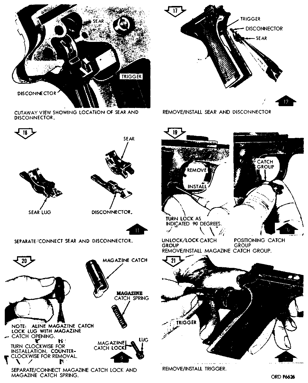
Detail strip the receiver: safety, hammer, sear, disconnector, magazine catch and trigger
Detail Strip tools required gunsmith recommendedFigures 26–30, steps 1–6 and 14–21. The hammer group and mainspring housing come out first; taking those two sub-assemblies apart (steps 7–13) is the separate procedure 'hammer-mainspring-housing-detail-strip'. Touches the sear and disconnector. The TM is a direct and general support (DS/GS) maintenance manual — work beyond the scope of the using organization.
Follows TM 9-1005-211-34 Direct and General Support Maintenance Manual: Pistol, Caliber .45, Automatic, M1911A1 — Headquarters, Department of the Army, para 34; figs. 26–30 (pp. 29–33) archive.org [8]
- Field strip the pistol and remove the magazine, leaving the receiver group.
- Remove the safety.Removed at this step:
Safety - Release the hammer so that it is down before you remove the hammer pin.
- Push the hammer pin out of the receiver.TipWhen installed, the head of the hammer pin is on the left side.Removed at this step:
Hammer pin - Remove the hammer group (hammer with hammer strut).Removed at this step:
Hammer group - Drive out the mainspring housing pin with a punch.Removed at this step:
Mainspring housing pin - Remove the mainspring housing assembly from the receiver.Removed at this step:
Mainspring housing assembly - Remove the grip safety.Removed at this step:
Grip safety - Remove the sear spring.Removed at this step:
Sear spring - Push the sear pin out from right to left.Removed at this step:
Sear pin - Remove the sear and disconnector.Removed at this step:
SearDisconnector - Separate the sear and disconnector.
- Turn the magazine catch lock 90 degrees to unlock the magazine catch group, and remove the magazine catch group from the receiver.Removed at this step:
Magazine catch group - Turn the magazine catch lock counterclockwise and separate the magazine catch lock and magazine catch spring from the magazine catch.WarningWherever springs are found to be under tension or pressure, extreme care should be exercised when removing components. Keep the finger and thumb over applicable components to prevent injury to personnel or loss of parts (TM para 29).Removed at this step:
Magazine catchMagazine catch lockMagazine catch spring - Remove the trigger.Removed at this step:
Trigger
Disassemble the hammer group and mainspring housing
Detail Strip tools required gunsmith recommendedFigures 28–29, steps 7–13, done after the hammer group and mainspring housing assembly are out of the receiver. The TM takes the mainspring out of the housing by depressing it and pushing out the straight headed pin; it lists no special housing tool for this. The TM is a direct and general support (DS/GS) maintenance manual — work beyond the scope of the using organization.
Follows TM 9-1005-211-34 Direct and General Support Maintenance Manual: Pistol, Caliber .45, Automatic, M1911A1 — Headquarters, Department of the Army, para 34; fig. 28 (p. 31) archive.org [8]
- Remove the hammer group and the mainspring housing assembly from the receiver (procedure 'receiver-fire-control-detail-strip', steps 2–7).
- Drive the hammer strut pin out from left to right.Removed at this step:
Hammer strut pin - Separate the hammer strut from the hammer.Removed at this step:
Hammer strutHammer - Depress the mainspring in the housing and push out the straight headed pin.WarningWherever springs are found to be under tension or pressure, extreme care should be exercised when removing components. Keep the finger and thumb over applicable components to prevent injury to personnel or loss of parts (TM para 29).Removed at this step:
Straight headed pin - Remove the mainspring (helical compression spring), mainspring cap pin and detent plunger from the mainspring housing.Removed at this step:
MainspringMainspring cap pinDetent plunger - Separate the detent plunger, helical compression spring and mainspring cap pin.
- Drive out the lanyard loop spring pin.Removed at this step:
Spring pin - Separate the lanyard loop from the housing.Removed at this step:
Lanyard loop
Strip the receiver: plungers, grips, plunger tube, ejector and grip screw bushings
Detail Strip tools required gunsmith recommendedFigures 31–32, steps 22–29. The plunger tube is staked to the receiver and the grip screw bushings are staked in; removing them is a replacement job for which the TM lists staking tools. The TM is a direct and general support (DS/GS) maintenance manual — work beyond the scope of the using organization.
Follows TM 9-1005-211-34 Direct and General Support Maintenance Manual: Pistol, Caliber .45, Automatic, M1911A1 — Headquarters, Department of the Army, para 34, 37b; figs. 31–32 (pp. 34–35) archive.org [8]
- Complete 'receiver-fire-control-detail-strip' so that the safety is out of the receiver.
- Remove the slide stop plunger, helical compression spring and safety plunger from the plunger tube.WarningWherever springs are found to be under tension or pressure, extreme care should be exercised when removing components. Keep the finger and thumb over applicable components to prevent injury to personnel or loss of parts (TM para 29).Removed at this step:
Slide stop plungerSlide stop plunger helical compression springSafety plunger - Remove the grip screws.Removed at this step:
Grip screws - Remove the plastic grips.Removed at this step:
Left hand gripRight hand grip - Unseat the plunger tube.WarningOnly to replace the tube: it is staked to the receiver, and the TM reinstalls it with a staking tool (para 37b).
- Remove the plunger tube.Removed at this step:
Plunger tube - Drive the ejector pin out from left to right.Removed at this step:
Ejector pin - Remove the cartridge ejector.Removed at this step:
Cartridge ejector - Remove the grip screw bushings with a screwdriver only if their threads are stripped or worn.WarningGrip screw bushings will not be removed from the receiver unless threads are stripped or worn (fig. 32 note).Removed at this step:
Grip screw bushings
Reassemble the extractor, firing pin and barrel link
Detail Reassembly tools required gunsmith recommendedFigure 20 run in reverse (the black-arrow assembly steps). The TM is a direct and general support (DS/GS) maintenance manual — work beyond the scope of the using organization.
Follows TM 9-1005-211-34 Direct and General Support Maintenance Manual: Pistol, Caliber .45, Automatic, M1911A1 — Headquarters, Department of the Army, para 33; fig. 20 (p. 25) archive.org [8]
- Insert the cartridge extractor into its hole at the rear of the slide and seat it.
- Align the slot of the extractor with the firing pin stop slot.TipThe figure shows the extractor's slot lying in line with the firing pin stop slot when it is correctly positioned.
- Insert the firing pin spring onto the firing pin and insert both into the rear of the slide, with the small loop of the spring to the rear.TipPara 33 note: when assembling firing pin and recoil springs, the small loop of the springs goes to the rear.
- Press the firing pin forward with a punch and slide the firing pin stop into its slot until it covers the firing pin.WarningWherever springs are found to be under tension or pressure, extreme care should be exercised when removing components. Keep the finger and thumb over applicable components to prevent injury to personnel or loss of parts (TM para 29).
- Place the barrel link between the barrel lugs.
- Install the barrel link pin from right to left.
- Reassemble the pistol per the entry's reassembly procedure.
Install the front and rear sights
Detail Reassembly tools required gunsmith recommendedFigure 21 assembly steps and para 32 j–k: the front sight is riveted (staked) to the slide with a riveting fixture; a loose rear sight is refitted by peening the top of the dovetail and drifting the sight back in with a brass drift. The TM is a direct and general support (DS/GS) maintenance manual — work beyond the scope of the using organization.
Follows TM 9-1005-211-34 Direct and General Support Maintenance Manual: Pistol, Caliber .45, Automatic, M1911A1 — Headquarters, Department of the Army, para 32 j–k; fig. 21 (p. 26) archive.org [8]
- Insert the front sight into its location in the slide.
- Rivet the front sight to the slide using the (improvised) riveting fixture.TipPara 32j: a loose front sight is restaked the same way.
- If the rear sight was loose, peen the top portion of the dovetail slot.
- Drift the rear sight into its dovetail slot from right to left with a brass drift.
Reassemble the receiver: bushings, ejector, plunger tube, grips and plungers
Detail Reassembly tools required gunsmith recommendedFigures 31–32 black-arrow assembly steps 1–7. The TM is a direct and general support (DS/GS) maintenance manual — work beyond the scope of the using organization.
Follows TM 9-1005-211-34 Direct and General Support Maintenance Manual: Pistol, Caliber .45, Automatic, M1911A1 — Headquarters, Department of the Army, para 38; figs. 31–32 (pp. 34–35) archive.org [8]
- If the grip screw bushings were removed, install new bushings and stake them with the bushing staking tool, a punch and hammer.
- Install the cartridge ejector.
- Install the ejector pin from right to left.
- If the plunger tube was removed, install it on the receiver and stake it with the staking tool and staking fixture (7/64-inch diameter drill rod).
- Install the plastic grips.
- Install the grip screws.
- Install the safety plunger, helical compression spring and slide stop plunger in the plunger tube.WarningWherever springs are found to be under tension or pressure, extreme care should be exercised when removing components. Keep the finger and thumb over applicable components to prevent injury to personnel or loss of parts (TM para 29).
Reassemble the mainspring housing and hammer group
Detail Reassembly tools required gunsmith recommendedFigures 28–29 black-arrow assembly steps 14–20. The TM is a direct and general support (DS/GS) maintenance manual — work beyond the scope of the using organization.
Follows TM 9-1005-211-34 Direct and General Support Maintenance Manual: Pistol, Caliber .45, Automatic, M1911A1 — Headquarters, Department of the Army, para 38; figs. 28–29 (pp. 31–32) archive.org [8]
- Connect the lanyard loop to the mainspring housing.
- Install the lanyard loop spring pin.
- Connect the detent plunger, helical compression spring (mainspring) and mainspring cap pin.
- Install the mainspring, cap pin and detent plunger into the mainspring housing.
- Depress the mainspring and install the straight headed pin.WarningWherever springs are found to be under tension or pressure, extreme care should be exercised when removing components. Keep the finger and thumb over applicable components to prevent injury to personnel or loss of parts (TM para 29).
- Connect the hammer strut to the hammer.
- Install the hammer strut pin from right to left.
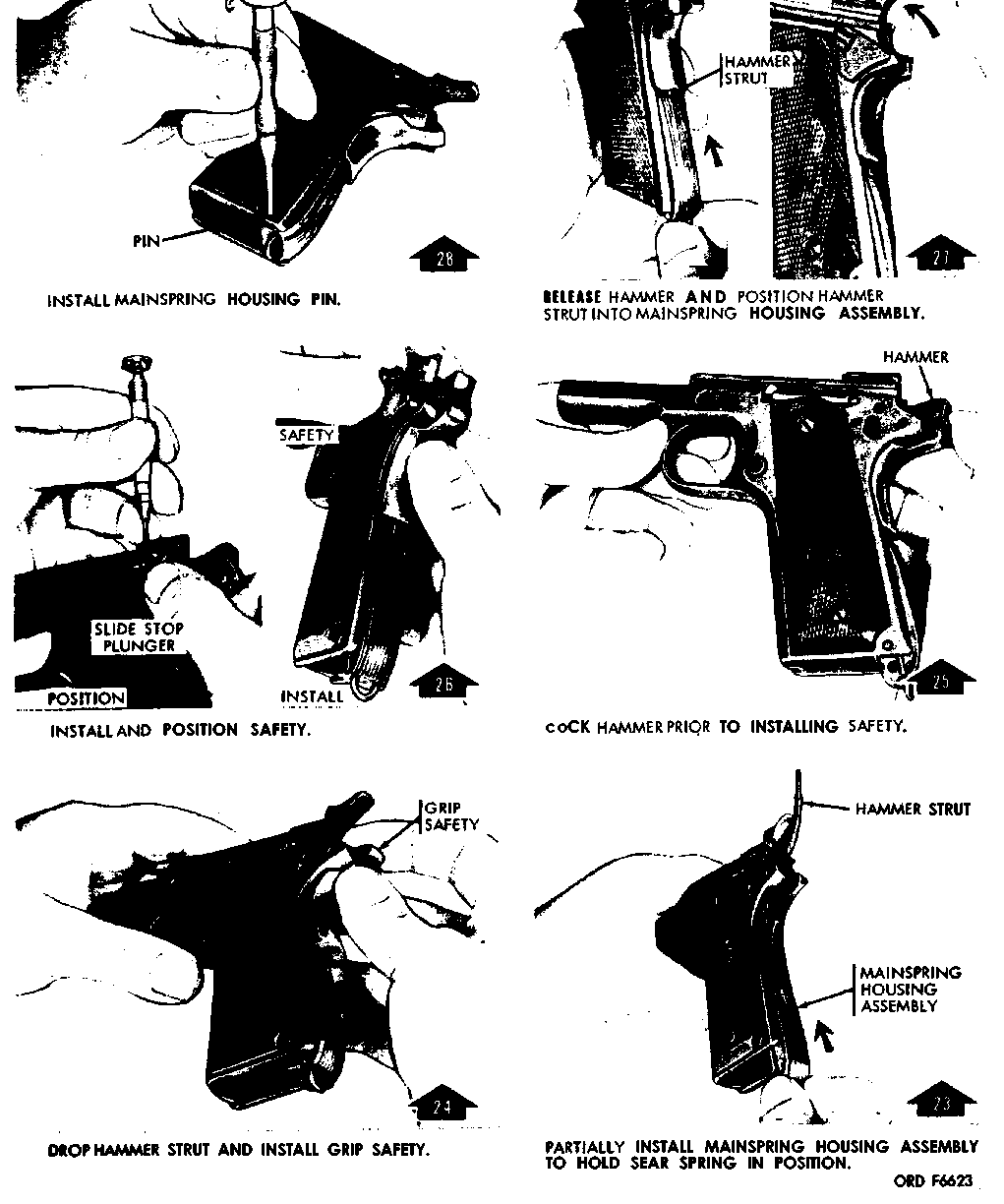
Reassemble the receiver fire control, magazine catch and mainspring housing
Detail Reassembly tools required gunsmith recommendedFigures 26–30 black-arrow assembly steps 8–13 and 21–28: trigger, magazine catch, sear and disconnector, hammer, sear spring, grip safety, safety, then the mainspring housing. Sets the sear spring against sear, disconnector and grip safety. The TM is a direct and general support (DS/GS) maintenance manual — work beyond the scope of the using organization.
Follows TM 9-1005-211-34 Direct and General Support Maintenance Manual: Pistol, Caliber .45, Automatic, M1911A1 — Headquarters, Department of the Army, para 38; figs. 26–30 (pp. 29–33) archive.org [8]
- Install the trigger.
- Assemble the magazine catch spring and magazine catch lock into the magazine catch: align the magazine catch lock lug with the magazine catch opening and turn the lock clockwise.
- Position the magazine catch group in the receiver and turn the lock 90 degrees to lock the group in place.
- Connect the sear and disconnector.
- Install the sear and disconnector in the receiver.
- Install the sear pin with the head of the pin on the left side.
- Install the hammer group and hammer pin, with the head of the pin on the left side.
- Raise the hammer strut and install the sear spring.TipFigure 28 shows a rear view of where the sear spring sits behind the sear and disconnector.
- Partially install the mainspring housing assembly to hold the sear spring in position.
- Drop the hammer strut and install the grip safety.
- Cock the hammer before installing the safety.
- Install and position the safety.TipThe figure marks the slide stop plunger at this step: the safety's pin portion goes in past the plunger in the plunger tube.
- Release the hammer and position the hammer strut into the mainspring housing assembly.
- Install the mainspring housing pin.
- Reassemble the slide group to the receiver and complete the final inspection checks of chapter 6 (trigger pull, safety and functioning).
Reassembly
ReassemblyReverse order. The barrel link must be tipped forward for the slide stop pin to pass through it.
- Insert the barrel into the front of the slide, chamber end first, and seat it fully.
- Install the barrel bushing over the barrel and rotate it clockwise (viewed from the muzzle) until it locks in place.
- Insert the recoil spring guide into the rear of the slide so it seats against the barrel lug.
- Slip the recoil spring over the guide from the front.
- Set the slide assembly onto the frame rails from the front and push it rearward.
- Align the takedown notch with the slide stop hole, tip the barrel link forward so its hole lines up with the frame hole, then insert the slide stop from the left and press it fully home.WarningNever force the slide stop. If it does not pass through, the barrel link is not aligned. Forcing it bends the link or scars the frame.TipA fingertip through the magazine well can tip the link forward into position.
- Install the recoil spring plug over the front of the recoil spring, press it in against spring pressure, and rotate the barrel bushing counterclockwise (viewed from the muzzle) to capture it.WarningThumb over the plug the entire time.
- Rack the slide several times to confirm it runs freely, then perform the function check.
Diagrams
public domainThese are reproduced from government technical manuals, which are not subject to copyright. Manufacturer manual diagrams are not reproduced here — the entry links to the manual instead.
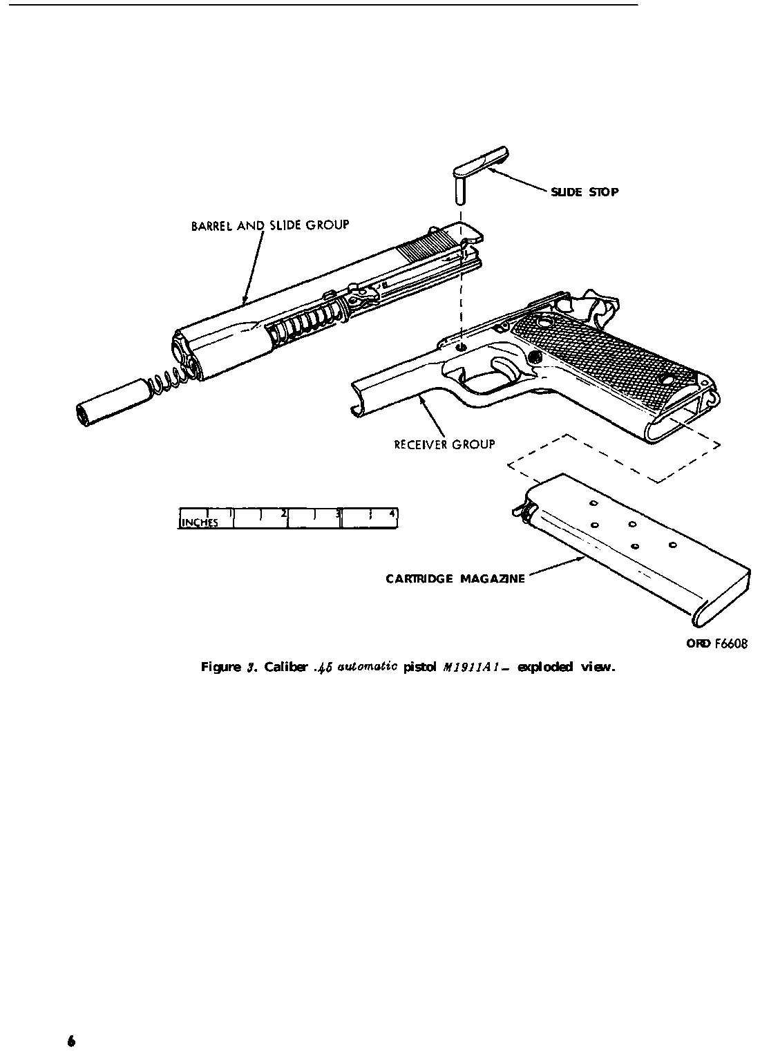
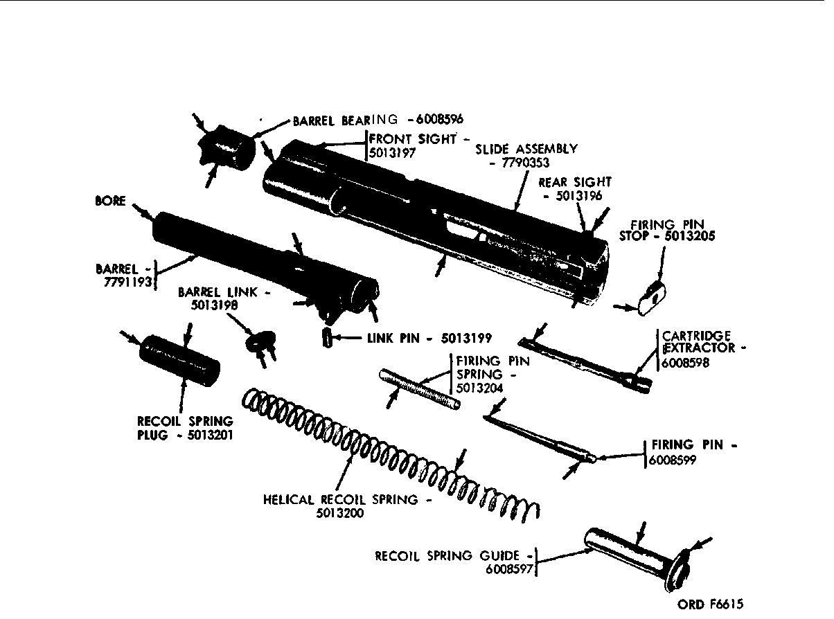
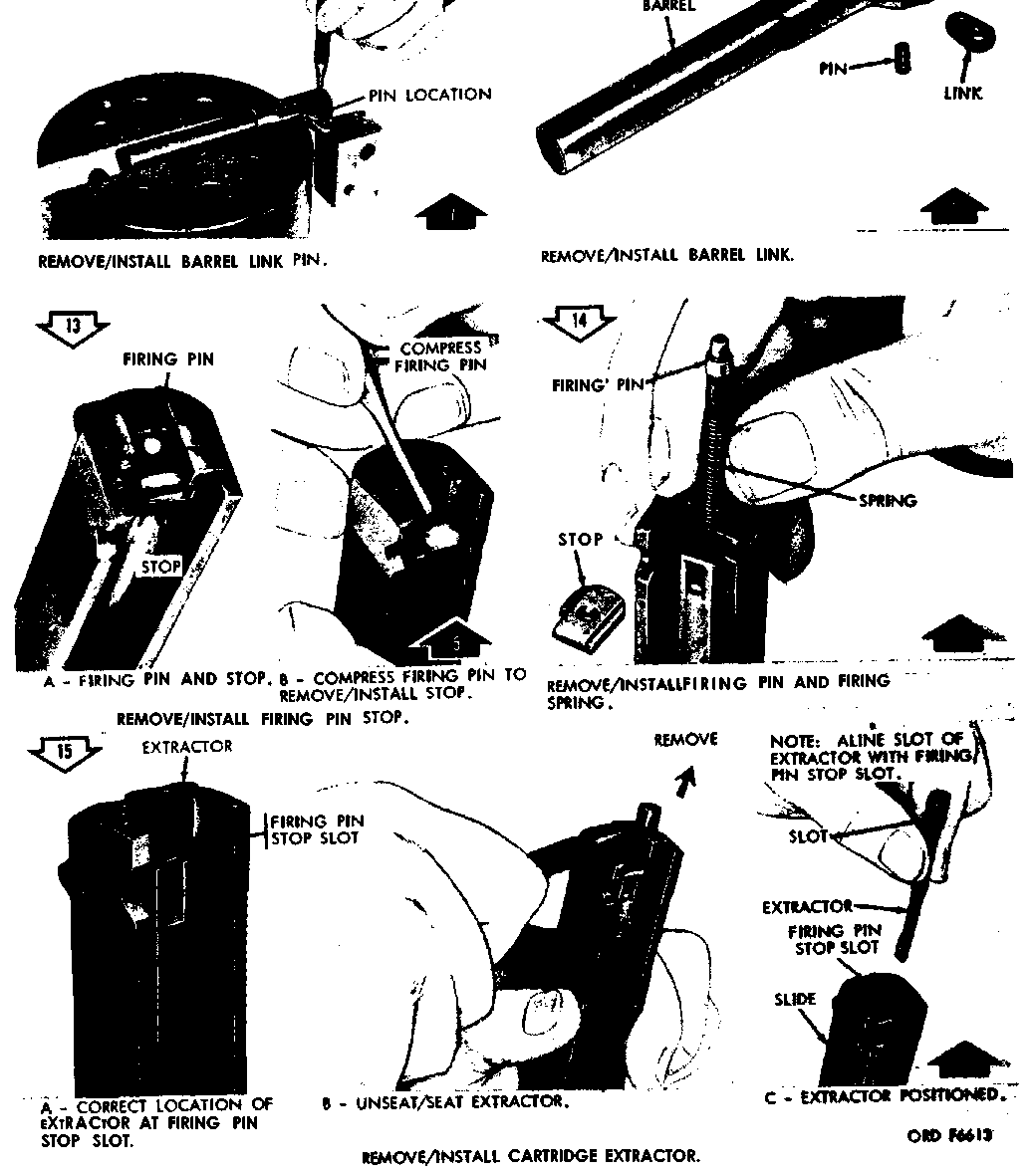
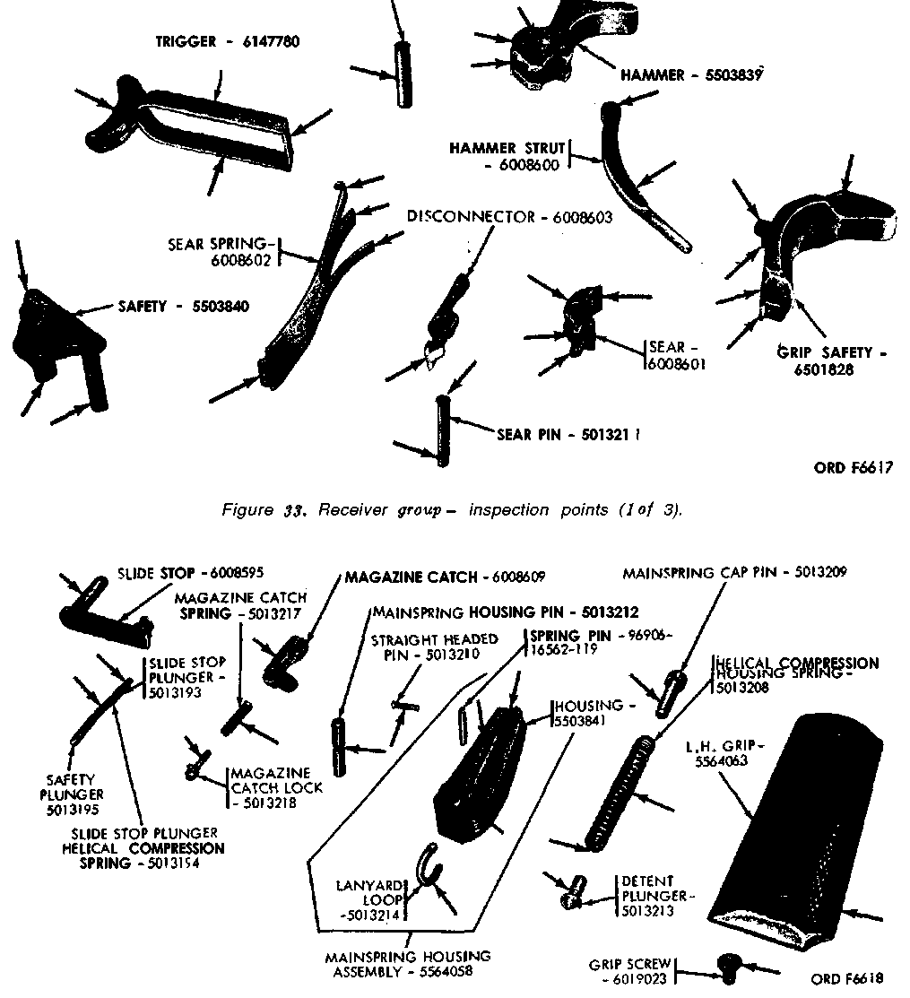
Patent drawings
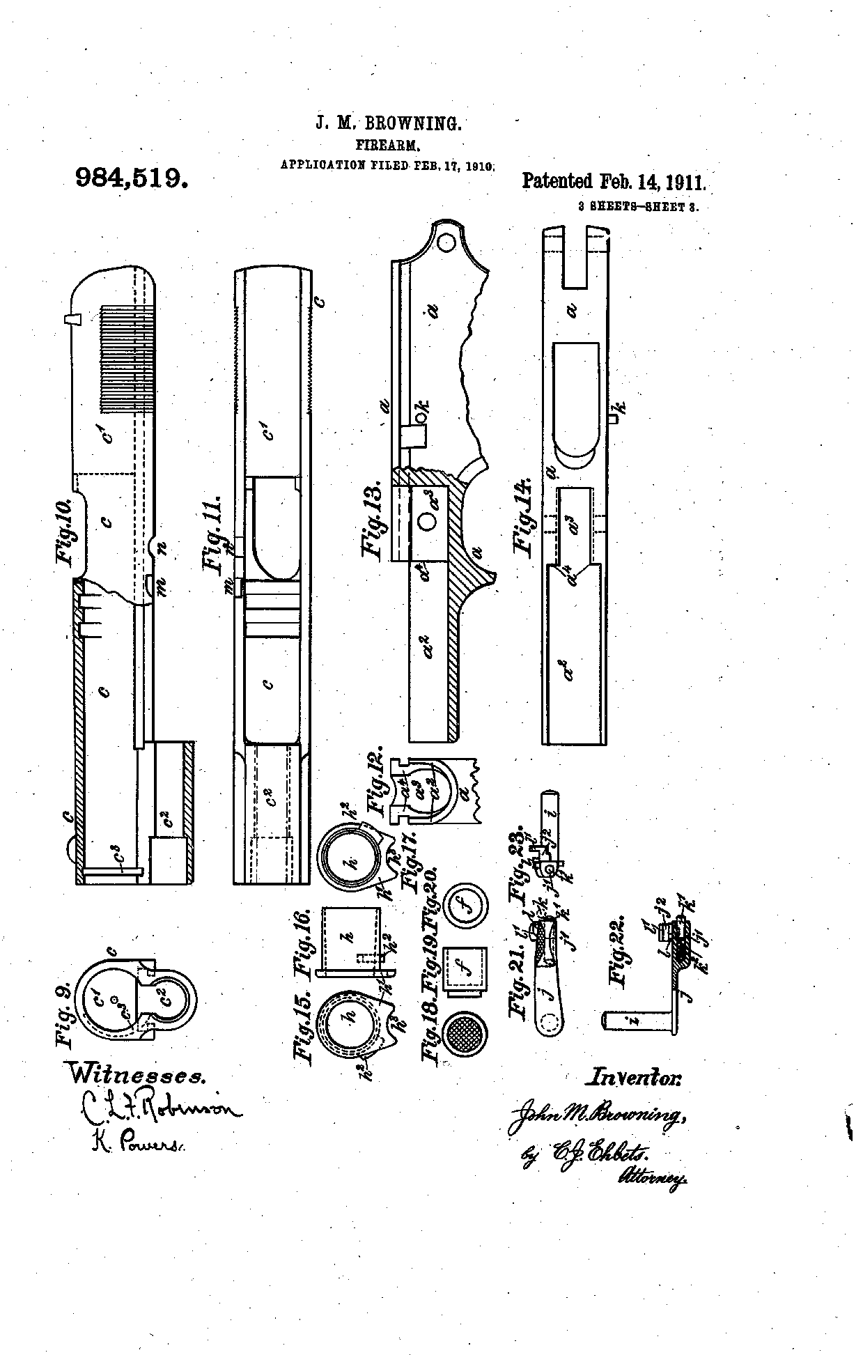
not under copyrightDrawings from US patents on this design. A patent shows the invention as the inventor filed it; the firearm that shipped can differ in detail, and later production often does. Use them to see how the parts relate, not as a parts reference or a procedure. Per the USPTO, the text and drawings of a patent are typically not subject to copyright; each patent here was checked for a copyright notice.
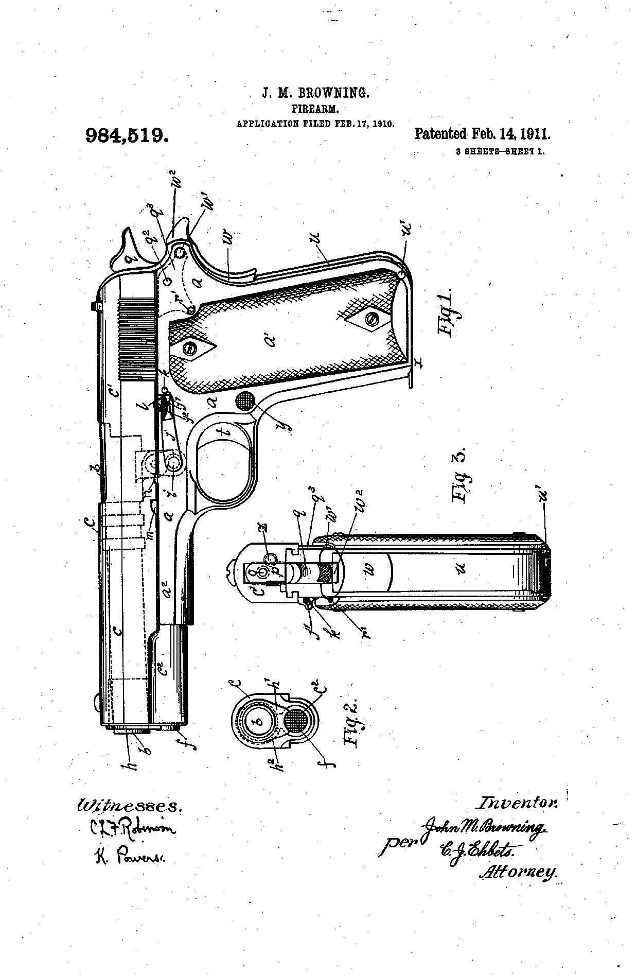
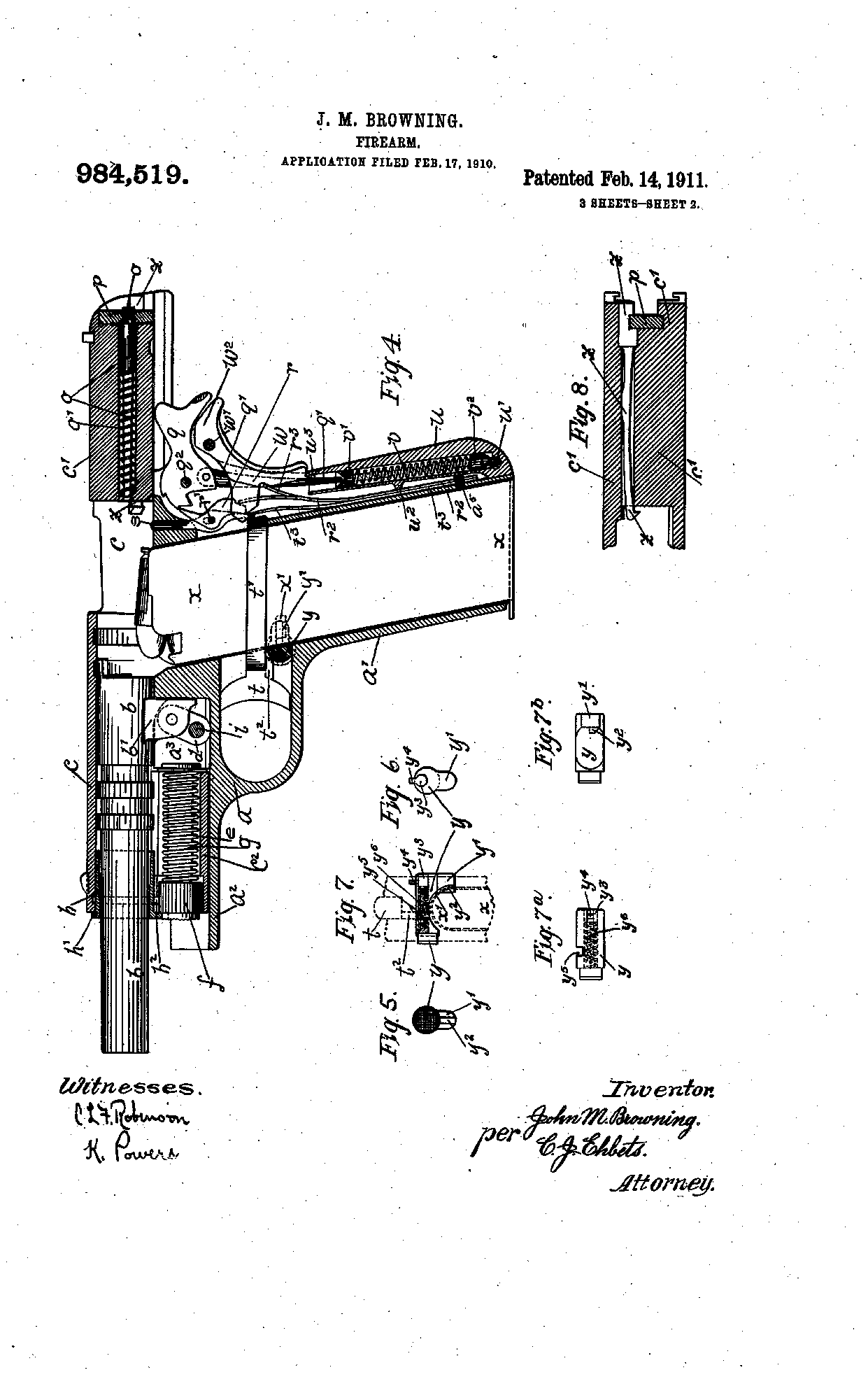
US Patent 984,519 — Firearm
John M. Browning · filed 1910-02-17 · granted 1911-02-14. Full patent (USPTO)
The complete Browning .45 pistol adopted as the M1911: slide (breech-slide) on the frame, single swinging-link barrel lock, barrel bushing, recoil (reaction) spring and plug, combined link-pin/slide stop, grip safety and magazine catch.
Why this is the M1911A1 / 1911 Government Model’s patent: named by a historical source — John Browning’s Valentine’s Day Gift to the US Military: the M1911 — Soldier of Fortune Magazine sofmag.com [12]: “On February 14, 1911, U.S. Patent No. 984,519 was issued to a quiet Ogden man: John Moses Browning. The document itself is dry and formal. But the words in its opening lines carry weight. That preamble marks the birth of the pistol that would become the Colt M1911.”
Torque specifications
No sourced torque values from the manufacturer are recorded for this firearm. Where a fastener has a specified torque — action screws, scope bases, muzzle devices, barrel nuts — get it from the manufacturer or a gunsmith rather than estimating it.
What the manufacturer does say: The manufacturer's documents give no torque value. They say: "Replace grip screws or bushings when damaged." (TM 9-1005-211-34, Direct and General Support Maintenance Manual, Pistol, Caliber .45, Automatic, M1911A1 (22 June 1964), archive.org item UnitedStatesArmyTm910052113422June1964, p. 18 (par. 17, General Maintenance; PDF p. 19)) "Check for split or damaged plastic grips and loose grip screws." (TM 9-1005-211-34, Direct and General Support Maintenance Manual, Pistol, Caliber .45, Automatic, M1911A1 (22 June 1964), archive.org item UnitedStatesArmyTm910052113422June1964, p. 38 (Chapter 6, Final Inspection; PDF p. 39))
Reported by other sources — not the manufacturer
| Fastener | Torque | Who says so, and their words | Where it comes from |
|---|---|---|---|
| Grip screws 1911 Government with Hogue G10 grips (factory hardware) |
12 in-lb 1.4 N·m · 1 ft-lb |
Reported by Hogue, Inc. “• Grip screws should be tightened to 12 in/lbs of torque with a correct fitting 3/32" hex driver.” |
1911 Govt 3/16" Thin Chain Link Solid Black G10 grip (product page) — Hogue, Inc. hogueinc.com [4] |
| Grip screws 1911 grip screws (Challis Grips general guidance) |
5 in-lb 0.56 N·m · 0.42 ft-lb |
Reported by Challis Grips “Do not use the long arm of a hex wrench (Allen wrench) to tighten grip screws. 5 in-lbs is sufficient and more is detrimental.” |
FAQ's about Bushings & Accessories — Challis Grips challisgrips.com [5] |
| Grip screws 1911 with Challis Hex Drive bushings and O-rings, hard grip materials (G10, ivory, aluminum) |
max. 10 in-lb 1.1 N·m · 0.83 ft-lb |
Reported by Challis Grips “Up to 10 in/lbs can be used for hard materials, but with any grip material 5 in/lbs is sufficient to hold the grips tight and prevent grip screws from loosening if you are using our O-rings.” |
FAQ's about Bushings & Accessories — Challis Grips challisgrips.com [5] |
| Grip screw bushings (Challis Hex Drive) 1911 steel and aluminum frames, Challis Hex Drive bushings |
18 in-lb 2 N·m · 1.5 ft-lb |
Reported by Challis Grips Threadlocker: "If our bushings are installed with the proper torque and used with the bushing O-rings they do not require Loctite. If you feel the need to use Loctite, we recommend blue." “We recommend 18 in-lbs torque when installing our bushings in steel and aluminum frames.” |
FAQ's about Bushings & Accessories — Challis Grips challisgrips.com [5] |
| Red-dot optic mounting screws (6-32 flat head, supplied) into EGW rear-dovetail sight mount 1911 with a G.I.-style rear sight cut (e.g. Springfield 1911A1) with the EGW 'Trijicon RMR / SRO, Holosun 407c / 507c Mount for GI 1911' (replaces the rear sight; for Trijicon RMR/SRO, Holosun 407C/50 |
15 in-lb 1.7 N·m · 1.2 ft-lb |
Reported by Evolution Gun Works (EGW) Remove the rear sight, install the EGW mount in the dovetail, tighten the set screw if applicable, place the optic on the mount, then apply blue Loctite and torque the optic screws. Threadlocker: Blue Loctite on the provided mounting screws (EGW instructions) “Torque mounting screws to 15in/lbs” |
Trijicon RMR / SRO, Holosun 407c / 507c Mount for GI 1911 (EGW product page, installation instructions section) — Evolution Gun Works (EGW) egwguns.com [9] |
| Red-dot optic mounting screws (supplied) into EGW rear-dovetail sight mount (Docter/Venom/Viper/FastFire footprint) 1911 with a G.I.-style rear sight cut (e.g. Springfield 1911A1) with the EGW '1911 GI Red Dot Mount | Fits Vortex Venom, Viper & Burris FastFire | EGW' (replaces the rear sight) |
15 in-lb 1.7 N·m · 1.2 ft-lb |
Reported by Evolution Gun Works (EGW) Remove the rear sight, install the EGW mount in the dovetail, tighten the set screw if applicable, place the optic on the mount, then apply blue Loctite and torque the optic screws. Threadlocker: Blue Loctite on the provided mounting screws (EGW instructions) “Torque mounting screws to 15 in/lbs” |
1911 GI Red Dot Mount | Fits Vortex Venom, Viper & Burris FastFire | EGW (EGW product page, installation instructions section) — Evolution Gun Works (EGW) egwguns.com [10] |
| DeltaPoint Pro M4x.7x15.8mm Torx screws through Leupold mount base into dovetail 1911 'Standard' with Leupold DeltaPoint Pro on the Leupold 1911 Standard base/dovetail (SKU 170904) |
25 in-lb 2.8 N·m · 2.1 ft-lb |
Reported by Leupold & Stevens, Inc. Remove the rear sight, fit the Leupold dovetail (part number up) in its place, set the mount base over it, seat the DeltaPoint Pro on the base posts, then torque the two Torx screws (press-fit). “Secure the screws by applying 25 in-lbs of torque.” |
Leupold DeltaPoint Pro Reflex Sight — Operating Instructions (Part #120278, artwork #120279P; English text with French translation) — Leupold & Stevens, Inc., PDF p. 1 (Installation section; mount li leupold.com [11] |
Parts list
Transcribed from the manufacturer's parts list (Colt Safety and Instruction Manual: Colt WWII Reproduction Pistol Model M1911A1 — Colt's Manufacturing Company, Inc., p. 47–48 colt.com [7]) — Section 6 Parts Illustration and List (2001) for Colt's WWII Reproduction M1911A1 (Fig. 12). Chosen over TM 9-1005-211-12 App. B, whose org repair parts list has only 10 items; -34 refers its list to separate TM -35P.. Key numbers refer to the exploded view in that document.
51 parts
| Key | Part | Part no. | Qty | Group |
|---|---|---|---|---|
| 1 | Slide | 1 | ||
| 2 | Front Sight | 1 | ||
| 3 | Rear Sight | 1 | ||
| 4 | Extractor | 1 | ||
| 5 | Firing Pin Spring | 1 | ||
| 6 | Firing Pin | 1 | ||
| 7 | Firing Pin Stop | 1 | ||
| 8 | Barrel | 1 | ||
| 9 | Barrel Bushing | 1 | ||
| 10 | Barrel Link | 1 | ||
| 11 | Barrel Link Pin | 1 | ||
| 12 | Recoil Spring Plug | 1 | ||
| 13 | Recoil Spring | 1 | ||
| 14 | Recoil Spring Guide | 1 | ||
| 15 | Receiver | 1 | ||
| 16 | Ejector | 1 | ||
| 17 | Ejector Pin | 1 | ||
| 18 | Left Hand Stock | 1 | ||
| 19 | Right Hand Stcok | 1 | ||
| 20 | Stock Screw Bushing | 4 | ||
| 21 | Stock Screw | 4 | ||
| 22 | Main Spring Housing (arched) | 1 | ||
| 23 | Main Spring Cap | 1 | ||
| 24 | Main Spring | 1 | ||
| 25 | Main Spring Housing Pin Retainer | 1 | ||
| 26 | Main Spring Cap Pin | 1 | ||
| 27 | Main Spring Housing Pin | 1 | ||
| 28 | Sear Spring | 1 | ||
| 29 | Trigger Assembly | 1 | ||
| 30 | Grip Safety | 1 | ||
| 31 | Hammer | 1 | ||
| 32 | Hammer Pin | 1 | ||
| 33 | Hammer Strut | 1 | ||
| 34 | Hammer Strut Pin | 1 | ||
| 35 | Sear | 1 | ||
| 36 | Sear Pin | 1 | ||
| 37 | Disconnector | 1 | ||
| 38 | Magazine Catch | 1 | ||
| 39 | Magazine Catch Spring | 1 | ||
| 40 | Magazine Catch Lock | 1 | ||
| 41 | Plunger Tube | 1 | ||
| 42 | Slide Stop Plunger | 1 | ||
| 43 | Plunger Spring | 1 | ||
| 44 | Safety Lock Plunger | 1 | ||
| 45 | Slide Stop | 1 | ||
| 46 | Safety Lock | 1 | ||
| 47 | Magazine Assembly | 1 | ||
| 48 | Magazine Spring | 1 | ||
| 49 | Magazine Follower | 1 | ||
| 50 | Lanyard Loop | 1 | ||
| 51 | Lanyard Loop Pin | 1 |
Function check
- Verify the pistol is unloaded before each check.
- Cock the hammer, engage the thumb safety, and press the trigger. The hammer must not fall.
- Disengage the thumb safety without touching the trigger. The hammer must not fall.
- With the hammer cocked and the safety off, press the trigger without depressing the grip safety. The hammer must not fall.
- Depress the grip safety and press the trigger. The hammer should fall.
- Hold the trigger to the rear, rack the slide, release the trigger and listen for the reset, then press again — the hammer should fall.
- Press the slide slightly out of battery and press the trigger. The hammer must not fall (disconnector check).
- If any of these checks fail, the pistol is unsafe. Stop and see a gunsmith.
Maintenance
Lubrication points
- Frame rails and the matching slide grooves
- Barrel hood and locking lugs
- Outside of the barrel where it passes through the bushing
- Barrel link and slide stop pin
- Disconnector head where it rides the slide
Cleaning notes
The 1911 runs best slightly wet on the rails compared to most modern polymer pistols. Keep the firing pin channel dry.
Suggested inspection interval: roughly every 3000 rounds. This is a general guideline, not a manufacturer specification.
Wear parts to inspect
Recoil spring · Extractor tension (internal extractor pistols) · Barrel link · Sear and hammer hooks · Magazine feed lips
Common issues
| Symptom | Likely cause | What to do |
|---|---|---|
| Slide stop will not go back in during reassembly | Barrel link is lying rearward instead of tipped forward | Tip the link forward so its hole aligns with the frame hole, then insert the slide stop without force. |
| Idiot scratch — a scrape on the frame above the trigger | Slide stop pin dragging across the frame during installation | Cosmetic only. Insert the slide stop straight rather than levering it in. |
| Failure to feed the last round | Worn magazine feed lips or a tired magazine spring | Replace the magazine. Magazines are the most common source of 1911 malfunctions. |
| Hammer follows the slide down | Worn or improperly stoned sear/hammer hooks | Stop shooting the pistol immediately. This is an unsafe condition. see a gunsmith |
Also covers
The procedures above are reported to apply to: Colt Government Model · Springfield Armory Mil-Spec and GI models · Rock Island Armory GI-pattern 1911s · Most full-size GI-pattern 1911 clones. Verify against the manual for your specific model.
Similar manual of arms
Legal notes
Sourcing
- Confidence
- high — Cross-checked against a primary source such as the manufacturer's manual or an issuing military technical manual.
- Verification
- Checked against an armorer/technical manual
- Last updated
- 2026-10-29
References
Every source this page draws on, with its web address so you can read it yourself. Numbers in brackets elsewhere on the page point here.
- [1] FM 23-35: Pistols and Revolvers — U.S. War Department / Department of the Army military technical manual primary source
- [2] TM 9-1005-211-34: Pistol, Caliber .45, Automatic, M1911A1 — U.S. Department of the Army military technical manual primary source
- [3] Colt Government Model Owner's Manual — Colt's Manufacturing Company manufacturer manual primary source
- [4] 1911 Govt 3/16" Thin Chain Link Solid Black G10 grip (product page) — Hogue, Inc. website secondary source
https://www.hogueinc.com/1911-govt-3-16-thin-chain-link-solid-black-g10 (checked 2026-09-27) - [5] FAQ's about Bushings & Accessories — Challis Grips website secondary source
https://www.challisgrips.com/pg/24-FAQ-s-about-Bushings-Accessories.aspx (checked 2026-09-27) - [6] TM 9-1005-211-34, Direct and General Support Maintenance Manual, Pistol, Caliber .45, Automatic, M1911A1 (22 June 1964), archive.org item UnitedStatesArmyTm910052113422June1964 — Headquarters, Department of the Army military technical manual primary source
https://archive.org/details/UnitedStatesArmyTm910052113422June1964 (checked 2026-09-27) - [7] Colt Safety and Instruction Manual: Colt WWII Reproduction Pistol Model M1911A1 — Colt's Manufacturing Company, Inc. manufacturer manual primary source
https://www.colt.com/wp-content/uploads/2023/02/wwiireproductionpistolmodelm1911a1.pdf (checked 2026-09-27) - [8] TM 9-1005-211-34 Direct and General Support Maintenance Manual: Pistol, Caliber .45, Automatic, M1911A1 — Headquarters, Department of the Army (1964) military technical manual primary source
https://archive.org/download/UnitedStatesArmyTm910052113422June1964/united_states_army_tm_9-1005-211-34%20-%2022_june_1964.pdf (checked 2026-10-03) - [9] Trijicon RMR / SRO, Holosun 407c / 507c Mount for GI 1911 (EGW product page, installation instructions section) — Evolution Gun Works (EGW) website secondary source
https://egwguns.com/trijicon-rmr-sro-holosun-407c-507c-mount-for-gi-1911 (checked 2026-10-11) - [10] 1911 GI Red Dot Mount | Fits Vortex Venom, Viper & Burris FastFire | EGW (EGW product page, installation instructions section) — Evolution Gun Works (EGW) website secondary source
https://egwguns.com/vortex-viper-venom-gi-1911-sight-mount-fits-burris-fastfire-and-docter (checked 2026-10-11) - [11] Leupold DeltaPoint Pro Reflex Sight — Operating Instructions (Part #120278, artwork #120279P; English text with French translation) — Leupold & Stevens, Inc. manufacturer manual secondary source
https://www.leupold.com/media/manuals/DeltaPoint_Pro_Manual_French_120279P.pdf (checked 2026-10-11) - [12] John Browning’s Valentine’s Day Gift to the US Military: the M1911 — Soldier of Fortune Magazine periodical secondary source
https://sofmag.com/m1911-patent-valentines-day/ (checked 2026-10-13) - [13] M1911 Stripping — M1911.ORG website secondary source
https://www.m1911.org/stripin1.htm (checked 2026-10-29) - [14] Exploded View: U.S. M1911A1 — American Rifleman (NRA) website secondary source
https://www.americanrifleman.org/content/exploded-view-u-s-m1911a1/ (checked 2026-10-29)
Notes: Illustrated on 2026-09-14 with the exploded view from TM 9-1005-211-34, the US Army maintenance manual for the M1911A1. A US Government work and therefore public domain. 1911 variants differ widely. Full-length guide rods, bull barrels, and ramped barrels each change the takedown sequence. This entry documents the GI/Government pattern only.