← All firearms · Printable work order
Ruger PC Carbine
- easy
- Shop tier 2
- high confidence
- Pistol-Caliber Carbine
- blowback
- takedown
- pistol caliber
- interchangeable magwell
field strip ~2 min · reassembly ~3 min · detail strip ~25 min
Specifications
- Manufacturer
- Sturm, Ruger & Co.
- Origin
- United States
- Category
- Pistol-Caliber Carbine
- Action
- Blowback
- Calibers
- 9x19mm Parabellum, .40 S&W
- Capacity
- 10 or 17 rounds depending on magazine
- Production
- 2017–present (in-production)
- Also known as
- PC9, PC Charger (pistol variant)
Model-specific safety
- This carbine separates into two halves at a barrel/receiver joint. The takedown is for transport and cleaning, and the two halves must be fully locked together before firing.
- The barrel assembly locks up through an adjustable mechanism. Ruger sets the fit with an adjustment knob on the barrel assembly, and a barrel that goes in with no resistance at all is not adjusted correctly.
- The bolt must be locked back before the barrel assembly will release, and the bolt stop must be engaged when installing it.
- The action uses a heavy tungsten dead-blow weight inside the bolt. Ruger does not describe disassembling it beyond removing the bolt top assembly, extractor and firing pin.
- The magazine well is interchangeable to accept different magazine types. Confirm the correct well is fitted for the magazines you are using.
If it will not go back together
Common ways this firearm resists reassembly, and what is actually wrong. Forcing a part that will not seat is how firearms get damaged.
-
The barrel assembly will not go into the receiver, or will not rotate to lock.
Why The bolt is not locked back with the bolt stop engaged, or the adjustment knob is screwed in too far.
Fix Lock the bolt back and engage the bolt stop, then try again. If it still will not seat, back the adjustment knob off counterclockwise, install the barrel, and retighten the knob.
Forcing it Forcing the barrel assembly against a closed bolt bears on the bolt face and the barrel block.
-
The barrel assembly goes in and locks, but feels loose or rattles.
Why The adjustment knob is backed off too far. It sets the lock-up tension and stays wherever it was left.
Fix Remove the barrel assembly, tighten the adjustment knob clockwise a little, and reinstall. Ruger's target is noticeable resistance as the barrel turns in, without it being difficult.
Forcing it Firing with a loose barrel lock-up costs accuracy and puts the joint under loads it was not adjusted for.
-
The barrel assembly will not come out even with the locking lever pushed forward.
Why The bolt is not locked back, or the assembly is being rotated the wrong way.
Fix Lock the bolt back, hold the locking lever forward, and rotate the barrel counterclockwise — the opposite of the direction that installed it.
Forcing it Levering on the barrel or forend to free it can bend the forend and mar the joint.
-
After reassembly the first shots group poorly.
Why The barrel assembly has not been seated.
Fix With the rifle empty and no magazine, slingshot the bolt from fully rearward two or three times, as Ruger directs after every barrel installation.
Under spring tension
- Recoil spring assembly
- Hammer spring
- Magazine spring
Easily lost parts
Magazine well retaining screw · Recoil spring assembly
Tools
| Tool | Required | Used for | Substitute |
|---|---|---|---|
| 5/32" hex wrench | Optional | Loosening the forend takedown screw and the two stock takedown screws. Not needed for the barrel takedown itself. | |
| 1/8" hex wrench | Optional | Removing the four handguard screws on handguard-equipped models. | |
| T10 Torx wrench | Optional | Removing the two front sight screws on handguard-equipped models. |
Shop difficulty
Shop tier 2 Tier 2 — moderate among rifles and carbines, for the full job: strip to the parts that get coated and put it back together working. 96 pieces, which is high for a long gun, with about six plungers or detents. Most of it goes in order. The traps are a flying extractor, a heavy bolt spring, and the takedown adjustment knob, which has to be re-set for lock-up.
Parts: 86 numbered parts (Complete carbine (86 line items)), from Ruger PC Carbine Instruction Manual — Sturm, Ruger & Co., Inc., p. 51–52 ruger-docs.s3.amazonaws.com [1].
Bench time: about 45 min to strip, 65 min to rebuild (estimate). Takedown, bolt (extractor), trigger guard assembly, chassis/forend and handguard screws. Many parts but mostly in order.
Small parts: 12 pins, 9 springs, 10 detents or plungers (counted from the manufacturer's parts list (one per key number unless a quantity is given))
What comes off for coating
- Barrel / forend: barrel assembly (takedown), adjustment knob, handguard / forend and screws, sights
- Receiver: bolt and recoil spring, charging handle, trigger guard assembly (cross pins), magazine release and latch
- Trigger guard assembly: hammer, strut, spring, trigger, plunger, spring, disconnector and spring, safety and detent plunger, bolt stop / last round parts
- Bolt: extractor pin, extractor, spring, firing pin and spring, bolt head retaining pins
Special tools
- 5/32 in and 1/8 in hex wrenches — Forend, stock and handguard screws
- pin punches — Trigger guard cross pins and extractor pin
Known pain points
- The extractor and its spring fly out of the bolt when the extractor pin is drifted unless they are held. (disassembly)
Source: Ruger PC Carbine Instruction Manual — Sturm, Ruger & Co., Inc. ruger-docs.s3.amazonaws.com [1] — “CAUTION: The extractor is under spring tension and may “fly” out of the bolt if it is not held in place during removal of the extractor pin.” - The bolt runs on a heavy recoil spring and slams shut on fingers. (both)
Source: Ruger PC Carbine Instruction Manual — Sturm, Ruger & Co., Inc. ruger-docs.s3.amazonaws.com [1] — “CAUTION: The bolt is under heavy spring tension and can injure fingers if it were to slam shut!”
See also 4 documented reassembly problems and their fixes.
Fit or check on rebuild
- Barrel lock-up tension (adjustment knob) — The knob must be re-set for firm lock-up.
- Seat the barrel by slingshotting the bolt — Ruger directs it after every barrel installation.
- Function check (safety, trigger reset, feeding, extraction) — Standard after any detail strip. No single source.
This is Pew-Takedown's rating, not the manufacturer's. How tiers are rated. Forum reports are owners' experience, not specifications.
Manufacturer videos
Official videos from Sturm, Ruger & Co.'s own channels, linked rather than copied. Where a video and the steps on this page differ, follow the manufacturer's manual and video.
- Ruger® PC Carbine™ Disassembly Tech Tip RugerFirearms
field strip · 2021-11-19
Covers: Ruger PC Carbine - Ruger® PC Carbine™ Reassembly Tech Tip RugerFirearms
reassembly · 2021-11-19
Covers: Ruger PC Carbine - Ruger® PC Carbine™ Cleaning Tech Tip RugerFirearms
cleaning · 2021-11-19
Covers: Ruger PC Carbine - Ruger® PC Carbine™ Bolt Lock Assembly Tech Tip RugerFirearms
detail reassembly · 2024-10-03
Covers: Ruger PC Carbine - Ruger® PC Charger™ Disassembly Tech Tip RugerFirearms
field strip · 2021-11-23
Covers: Ruger PC Charger (pistol variant) - Ruger® PC Charger™ Reassembly Tech Tip RugerFirearms
reassembly · 2021-11-23
Covers: Ruger PC Charger (pistol variant)
Procedures
Clear and Make Safe
Clear & Make Safe- Point the muzzle in a safe direction and keep your finger off the trigger.
- Press the magazine release and remove the magazine.
- Pull the charging handle fully to the rear and lock the bolt open by pressing up on the bolt stop.
- Visually confirm there is no cartridge in the chamber, using a light.WarningRuger's own disassembly warning is explicit: unload the firearm before cleaning, lubrication, disassembly or assembly.
- Place the safety in the "ON" position if the hammer is cocked, and remove all live ammunition from the work area.
Field Strip — Barrel Assembly Removal
Field StripManufacturer’s videos: Ruger® PC Carbine™ Disassembly Tech Tip RugerFirearms · Ruger® PC Charger™ Disassembly Tech Tip RugerFirearms
- Complete the Clear and Make Safe procedure. Leave the bolt locked back — the barrel assembly will not release with the bolt closed.
- Push the locking lever forward to unlock the barrel assembly.WarningForward, not rearward. The lever unlocks the joint; it does not need to be pushed back or pulled.
- While holding the locking lever forward, rotate the barrel assembly counterclockwise and pull it out of the receiver.TipCounterclockwise to remove, clockwise to install. Ruger illustrates both directions.Removed at this step:
Barrel assembly - Retract the charging handle fully rearward and slowly release it until the bolt comes to rest in its forward position.WarningDo not leave the bolt locked back on the separated receiver.
- Clean the bore from the breech end of the separated barrel, and clean the bolt face, chamber and receiver interior.TipThis is the extent of disassembly Ruger describes for routine inspection, cleaning and lubrication.
Barrel / Forend Separation
Field Strip tools requiredManufacturer’s videos: Ruger® PC Carbine™ Disassembly Tech Tip RugerFirearms · Ruger® PC Charger™ Disassembly Tech Tip RugerFirearms
- Complete the barrel assembly removal first.
- Use a 5/32" hex wrench to loosen — do not remove — the takedown screw in the forend.
- Slide the barrel out of the forend.Removed at this step:
Forend - To reassemble, insert the barrel into the forend and tighten the takedown screw with the 5/32" hex wrench.
Reassembly and Lock-Up Adjustment
ReassemblyManufacturer’s videos: Ruger® PC Carbine™ Reassembly Tech Tip RugerFirearms · Ruger® PC Charger™ Reassembly Tech Tip RugerFirearms
- If this is the first time the barrel assembly is being installed, or the fit needs correcting, loosen the adjustment knob by turning it counterclockwise as far as finger pressure allows.TipRuger's instruction: after the first adjustment, later installations need only the insert-and-rotate step.
- Lock the bolt back with the bolt stop engaged.
- Insert the barrel assembly into the receiver and rotate it clockwise until it locks into place.WarningClockwise to install. The locking lever does not need to be held for installation.
- Tighten the adjustment knob by rotating it clockwise until the barrel assembly is securely connected.WarningYou should feel some resistance turning the barrel assembly into the receiver, but it should not be difficult. If it is, remove the assembly and back the knob off.
- Dry cycle the action to seat the barrel assembly: with no magazine and an empty chamber, pull the bolt handle fully to the rear while holding the bolt lock up, then release it and let it slingshot forward. Repeat two or three times.TipRuger states this seating cycle gives the best fired-shot accuracy after a barrel installation.
- Perform the function check before any live firing.
Patent drawings
not under copyrightDrawings from US patents on this design. A patent shows the invention as the inventor filed it; the firearm that shipped can differ in detail, and later production often does. Use them to see how the parts relate, not as a parts reference or a procedure. Per the USPTO, the text and drawings of a patent are typically not subject to copyright; each patent here was checked for a copyright notice.
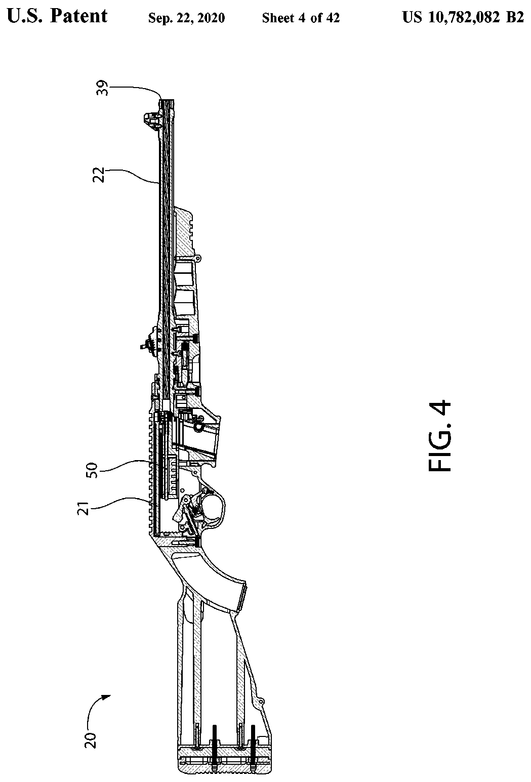
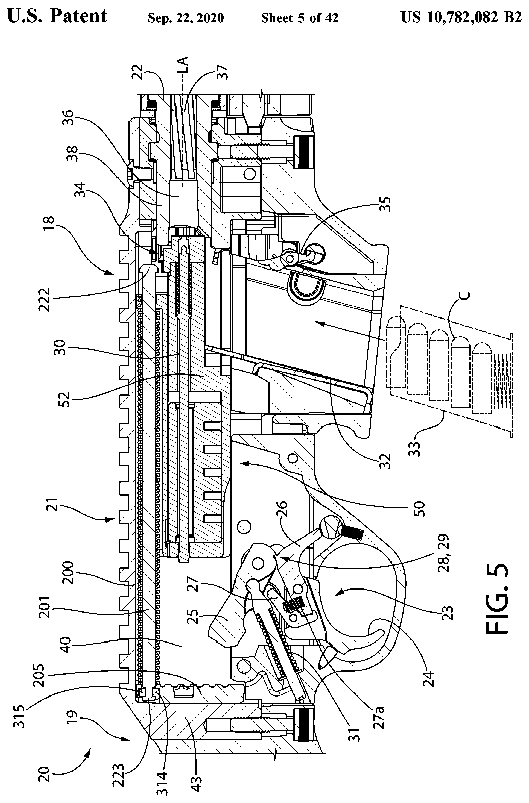
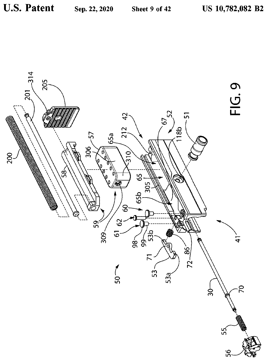
US Patent 10,782,082 — Bolt assembly for blowback type firearms
Todd Wilkinson, Frank J. Saunders · assigned to Sturm, Ruger & Company, Inc. · filed 2018-10-16 · granted 2020-09-22. Full patent (USPTO)
The PC Carbine's blowback bolt with its dead-blow weight, recoil spring and how the bolt sits in the receiver over the trigger group.
Why this is the Ruger PC Carbine’s patent: listed on the maker’s patent-marking page — Ruger Patents — Sturm, Ruger & Co., Inc. ruger.com [9]: “PC Carbine™ 10,782,082; 10,677,552”
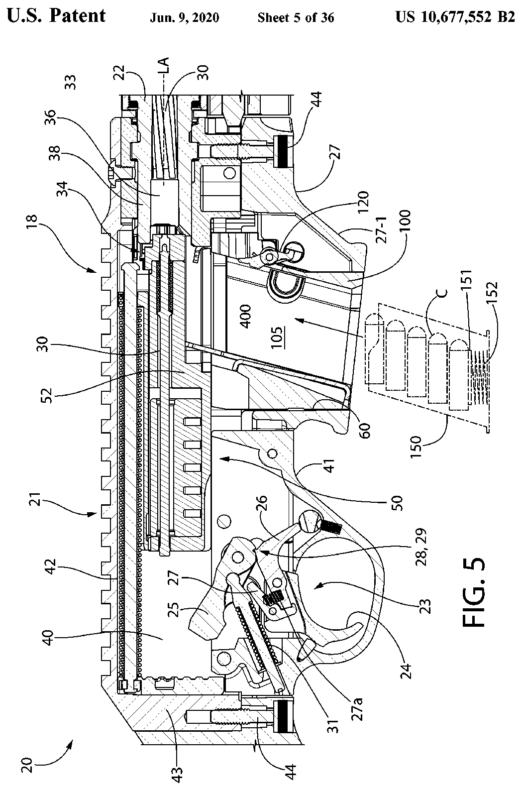
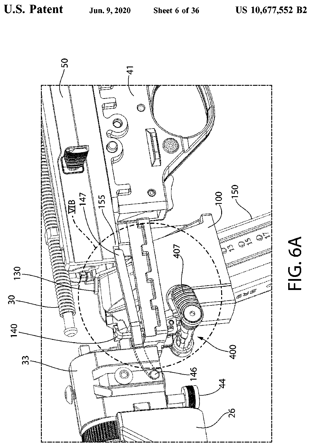
US Patent 10,677,552 — Modular magazine well insert system for firearm
Todd Wilkinson, Frank J. Saunders · assigned to STURN RUGER & COMPANY Inc · filed 2019-01-07 · granted 2020-06-09. Full patent (USPTO)
The PC Carbine's interchangeable magazine-well inserts in the mid-stock and how they mount with the receiver and trigger group.
Why this is the Ruger PC Carbine’s patent: listed on the maker’s patent-marking page — Ruger Patents — Sturm, Ruger & Co., Inc. ruger.com [9]: “PC Carbine™ 10,782,082; 10,677,552”
Torque specifications
| Fastener | Torque | Sequence, notes and the source's words | Where it comes from |
|---|---|---|---|
| Stock takedown screws (2) | 65 in-lb 7.3 N·m · 5.4 ft-lb |
“Secure the two takedown screws to 65 inch-pounds with a 5/32” hex wrench.” |
Ruger PC Carbine Instruction Manual — Sturm, Ruger & Co., Inc., p. 18 ruger-docs.s3.amazonaws.com [1] |
| Magazine release cap head screw | 15 in-lb 1.7 N·m · 1.2 ft-lb |
“The magazine release button compresses the latch stud spring and is retained by the cap head screw, torqued to 15 inch-pounds.” |
Ruger PC Carbine Instruction Manual — Sturm, Ruger & Co., Inc., p. 19 ruger-docs.s3.amazonaws.com [1] |
| Charging handle cap screw | 65 in-lb 7.3 N·m · 5.4 ft-lb |
With the bolt closed, align the conical base of the charging handle with the countersink on the bolt through the receiver slot before tightening. Ruger says to verify this torque every 1,000 rounds or whenever the charging handle is removed and reinstalled. “Tighten the cap screw to 65 inch-pounds to ensure the handle is secure.” |
Ruger PC Carbine Instruction Manual — Sturm, Ruger & Co., Inc., p. 20 ruger-docs.s3.amazonaws.com [1] |
| Handguard screws (4) Models with handguard |
45 in-lb 5.1 N·m · 3.7 ft-lb |
Slide the handguard on without letting it touch the barrel, sight cutouts at 12 o'clock, then tighten the four screws in an alternating sequence with a 1/8" hex wrench. “Torque each of the handguard screws to 45 in-lbs.” |
Ruger PC Carbine Instruction Manual — Sturm, Ruger & Co., Inc., p. 40 ruger-docs.s3.amazonaws.com [1] |
| Front sight screws (2) Models with handguard |
20 in-lb 2.3 N·m · 1.7 ft-lb |
Slide the front sight on from the muzzle end and use a T10 Torx wrench. “Torque each of the front screws to 20 in-lbs.” |
Ruger PC Carbine Instruction Manual — Sturm, Ruger & Co., Inc., p. 41 ruger-docs.s3.amazonaws.com [1] |
Notes: From Ruger's PC Carbine manual. The barrel assembly itself is not torqued: it rotates into the receiver and its lock-up is set with the adjustment knob, as described in the reassembly procedure.
Reported by other sources — not the manufacturer
| Fastener | Torque | Who says so, and their words | Where it comes from |
|---|---|---|---|
| Receiver screws (2), 5/32" hex Magpul PC Backpacker Stock (MAG1076) on a Ruger PC Carbine (9mm / .40 S&W) |
65 in-lb 7.3 N·m · 5.4 ft-lb |
Reported by Magpul Industries “use a 5/32” hex key to install the two receiver screws, and tighten to 65 in-lbs. according to manufacturer’s instructions.” |
Magpul MAG1076 PC Backpacker Stock (Ruger PC Carbine) — Installation Instructions — Magpul Industries, PDF p. 1 of 3 magpul.com [3] |
| Forend screw (forend to barrel assembly), 5/32" hex Magpul PC Backpacker Stock (MAG1076) on a Ruger PC Carbine (9mm / .40 S&W) |
65 in-lb 7.3 N·m · 5.4 ft-lb |
Reported by Magpul Industries “Using a 5/32” hex key, tighten the forend screw to 65 in-lbs.” |
Magpul MAG1076 PC Backpacker Stock (Ruger PC Carbine) — Installation Instructions — Magpul Industries, PDF p. 1 of 3 magpul.com [3] |
| Receiver-to-chassis 12-24 x 3/4 hex screws (2; replace factory stock screws) Midwest Industries Ruger PC Carbine Take-Down Chassis (MI-RPCC / MI-RPCCSF) |
55 in-lb 6.2 N·m · 4.6 ft-lb |
Reported by Midwest Industries, Inc. Threadlocker: Loctite (instructions: 'Degrease screws prior to installing loctite') “Drop the two provided 12-24x3/4 hex screw in the screw holes and tighten to 55 inch/pounds, securing receiver to chassis.” |
Midwest Industries Ruger PC Carbine Take-Down Chassis (MI-RPCC / MI-RPCCSF) — Installation Instructions — Midwest Industries, Inc., PDF p. 1 (single page) midwestindustriesinc.com [4] |
| AR grip adaptor 1/4-20 x 1.5" screw Midwest Industries Ruger PC Carbine Take-Down Chassis (MI-RPCC / MI-RPCCSF) |
35 in-lb 4 N·m · 2.9 ft-lb |
Reported by Midwest Industries, Inc. Threadlocker: Blue Loctite may be used “install the ¼-20x1.5” screw from the top and torque screw to 35 inch/pounds.” |
Midwest Industries Ruger PC Carbine Take-Down Chassis (MI-RPCC / MI-RPCCSF) — Installation Instructions — Midwest Industries, Inc., PDF p. 1 (single page) midwestindustriesinc.com [4] |
| AR grip screw Midwest Industries Ruger PC Carbine Take-Down Chassis (MI-RPCC / MI-RPCCSF) |
45 in-lb 5.1 N·m · 3.7 ft-lb |
Reported by Midwest Industries, Inc. “Install AR style grip with provided grip screw/washer and torque grip screw to 45 inch/pounds.” |
Midwest Industries Ruger PC Carbine Take-Down Chassis (MI-RPCC / MI-RPCCSF) — Installation Instructions — Midwest Industries, Inc., PDF p. 1 (single page) midwestindustriesinc.com [4] |
| Hand guard bottom retaining screw (replaces factory forearm screw) Midwest Industries Ruger PC Carbine Extended M-Lok Hand Guard (MI-CRPC9-X) |
55 in-lb 6.2 N·m · 4.6 ft-lb |
Reported by Midwest Industries, Inc. “Then tighten the bottom hand guard retaining screw to 55-inch/pounds.” |
Midwest Industries Ruger PC Carbine Extended M-Lok Hand Guard (MI-CRPC9-X) — Installation Instructions — Midwest Industries, Inc., PDF p. 1 (single page) midwestindustriesinc.com [5] |
| M-Lok rail section screws Midwest Industries Ruger PC Carbine Extended M-Lok Hand Guard (MI-CRPC9-X) |
15 in-lb 1.7 N·m · 1.2 ft-lb |
Reported by Midwest Industries, Inc. “Install M-Lok rails to the outside of the handguard, torque M-Lok screws to 15 in/lbs.” |
Midwest Industries Ruger PC Carbine Extended M-Lok Hand Guard (MI-CRPC9-X) — Installation Instructions — Midwest Industries, Inc., PDF p. 1 (single page) midwestindustriesinc.com [5] |
| M-Lok mount cross bolt (on factory lower forearm rail) Midwest Industries MI-PC9M M-Lok Mount on Ruger PC Carbine models 19100, 19101, 19102 |
50 in-lb 5.6 N·m · 4.2 ft-lb |
Reported by Midwest Industries, Inc. “Push the cross bolt through the hole and torque the bolt to 50 inch/pounds.” |
Midwest Industries MI-PC9M Ruger PC-9 M-Lok Mount (models 19100, 19101, 19102) — Installation Instructions — Midwest Industries, Inc., PDF p. 1 (single page) midwestindustriesinc.com [6] |
| Bolt (charging) handle screw (factory screw re-used) Midwest Industries Ruger PC9 Bolt Handle on a Ruger PC Carbine |
65 in-lb 7.3 N·m · 5.4 ft-lb |
Reported by Midwest Industries, Inc. Re-check the torque after 1k rounds (instructions step 9). “Check to make sure the bolt handle is seated and aligned correctly, torque the screw to 65 inch/pounds.” |
Midwest Industries Ruger PC9 Bolt Handle — Installation Instructions — Midwest Industries, Inc., PDF p. 1 (single page) midwestindustriesinc.com [7] |
| Take down block bolts (factory bolts re-used) Midwest Industries Ruger PC Charger Handguard (MI-RC-4.875) on the Ruger PC Charger (pistol variant) |
45 in-lb 5.1 N·m · 3.7 ft-lb |
Reported by Midwest Industries, Inc. Threadlocker: Blue thread locker “apply blue thread loc to the take down block bolts and install the MI take down block -- torque the bolts to 45-inch pounds.” |
Midwest Industries Ruger PC9 Charger Handguard (MI-RC-4.875) — Installation Instructions — Midwest Industries, Inc., PDF p. 1 (single page) midwestindustriesinc.com [8] |
| Handguard bolt Midwest Industries Ruger PC Charger Handguard (MI-RC-4.875) on the Ruger PC Charger (pistol variant) |
30 in-lb 3.4 N·m · 2.5 ft-lb |
Reported by Midwest Industries, Inc. Threadlocker: Blue Loctite “Apply blue Loctite to the handguard bolt. Install the bolt and torque to 30-inch pounds.” |
Midwest Industries Ruger PC9 Charger Handguard (MI-RC-4.875) — Installation Instructions — Midwest Industries, Inc., PDF p. 1 (single page) midwestindustriesinc.com [8] |
| M-Lok rail section bolts Midwest Industries Ruger PC Charger Handguard (MI-RC-4.875) on the Ruger PC Charger (pistol variant) |
15 in-lb 1.7 N·m · 1.2 ft-lb |
Reported by Midwest Industries, Inc. “The M-Lok rail section may be installed in your choice of locations torque the bolts to 15-inch pounds.” |
Midwest Industries Ruger PC9 Charger Handguard (MI-RC-4.875) — Installation Instructions — Midwest Industries, Inc., PDF p. 1 (single page) midwestindustriesinc.com [8] |
Materials and factory finish
As stated by Sturm, Ruger & Co.. Prep, masking and cure depend on these; a polymer or aluminium part, a nitrided or anodised finish, and a blued steel part are each a different job. Variants with other finishes may exist — check the maker's page for the exact SKU on the bench.
| Component | Material | Factory finish | Where it comes from |
|---|---|---|---|
| Receiver Model 19100 | Aluminum Alloy | Type III Hard-Coat Anodized | Ruger PC Carbine Autoloading Rifle — Specifications (model 19100) — Sturm, Ruger & Co. ruger.com [2] “Receiver Material Aluminum Alloy … Receiver Finish Type III Hard-Coat Anodized” |
| Receiver Model 19100 | aerospace-grade aluminum billet | Type III hard-coat anodized | Ruger PC Carbine Autoloading Rifle — Specifications (model 19100) — Sturm, Ruger & Co. ruger.com [2] “CNC-machined from an aerospace-grade aluminum billet, the receiver includes an integrated Picatinny-style rail and is Type III hard-coat anodized for maximum durability.” |
| Barrel Model 19100 | chrome-moly steel | — | Ruger PC Carbine Autoloading Rifle — Specifications (model 19100) — Sturm, Ruger & Co. ruger.com [2] “Cold hammer-forged, chrome-moly steel barrel with ultra-precise rifling provides exceptional accuracy and longevity.” |
| Bolt Model 19100 | chrome-moly steel | — | Ruger PC Carbine Autoloading Rifle — Specifications (model 19100) — Sturm, Ruger & Co. ruger.com [2] “Bolt is machined from heat treated, chrome-moly steel to ensure strength, structural integrity and durability.” |
| Stock Model 19100 | glass-filled nylon | — | Ruger PC Carbine Autoloading Rifle — Specifications (model 19100) — Sturm, Ruger & Co. ruger.com [2] “Stock Black Synthetic … Durable, glass-filled nylon synthetic buttstock features a proprietary texture for enhanced control and an integral sling mount for rapid sling attachment .” |
Parts list
Transcribed from the manufacturer's parts list (Ruger PC Carbine Instruction Manual — Sturm, Ruger & Co., Inc., p. 51–52 ruger-docs.s3.amazonaws.com [1]) — Ruger PC Carbine. Exploded views on pp. 53–57. Key numbers refer to the exploded view in that document.
86 parts
| Key | Part | Part no. | Qty | Group |
|---|---|---|---|---|
| 1 | Stock Assembly – Complete | 1 | ||
| 2 | Low Profile Cap Screw | 1 | ||
| 3 | Magazine Release Button | 1 | ||
| 4 | Magazine Release Spring | 1 | ||
| 5 | Magazine Release Stud | 1 | ||
| 6 | Stock Assembly | 1 | ||
| 7 | Butt Pad Holder | 1 | ||
| 8 | Butt Plate Screw | 2 | ||
| 9 | Pad Spacer | 1 | ||
| 10 | Recoil Pad Assembly | 1 | ||
| 11 | Recoil Pad Screws | 1 | ||
| 12 | Barrel Assembly with Forend – Complete | 1 | ||
| 13 | Thread Protector | 1 | ||
| 14 | O-Ring | 1 | ||
| 15 | Front Sight | 1 | ||
| 16 | Sight Screws | 4 | ||
| 17 | Forend Assembly | 1 | ||
| 18 | Locking Lever | 1 | ||
| 19 | Mounting Screws | 2 | ||
| 20 | Takedown Block | 1 | ||
| 21 | Detent Spring | 1 | ||
| 22 | Detent Plunger | 1 | ||
| 23 | Locking Plunger Spring | 1 | ||
| 24 | Locking Plunger Detent | 1 | ||
| 25 | Locking Plunger | 1 | ||
| 26 | Barrel Spacer | 1 | ||
| 27 | Adjustment Ring | 1 | ||
| 28 | Barrel | 1 | ||
| 29 | Rear Sight Base | 1 | ||
| 30 | Rear Sight Slide | 1 | ||
| 31 | Rear Sight Aperture | 1 | ||
| 32 | Set Screws | 2 | ||
| 33 | Magazine Well Assemblies (SR9/G9/American) – Complete | 1 | ||
| 34 | Ejector | 1 | ||
| 35 | Magazine Well, SR9 | 1 | ||
| 36 | Last Round Plunger | 1 | ||
| 37 | Latch Pin | 1 | ||
| 38 | Magazine Latch, SR9 | 1 | ||
| 39 | Magazine Latch Spring | 1 | ||
| 40 | Magazine Well, G9 | 1 | ||
| 41 | Magazine Well, American 9mm | 1 | ||
| 42 | Magazine Latch, American 9mm | 1 | ||
| 43 | Last Round Catch | 1 | ||
| 44 | Last Round Spring | 1 | ||
| 45 | Last Round Pivot Pin | 1 | ||
| 46 | Barrel Block | 1 | ||
| 47 | Trigger Assembly – Complete Parts so marked must be factory fit. | 1 | ||
| 48 | Hammer Strut Washer Parts so marked must be factory fit. | 1 | ||
| 49 | Hammer Strut Spring Parts so marked must be factory fit. | 1 | ||
| 50 | Hammer Strut Parts so marked must be factory fit. | 1 | ||
| 51 | Hammer Parts so marked must be factory fit. | 1 | ||
| 52 | Hammer Pivot Pin Parts so marked must be factory fit. | 1 | ||
| 53 | Trigger Guard Parts so marked must be factory fit. | 1 | ||
| 54 | Bolt Stop | 1 | ||
| 55 | Bolt Stop Spring | 1 | ||
| 56 | Trigger Pivot Pin Parts so marked must be factory fit. | 1 | ||
| 57 | Trigger Plunger Spring Parts so marked must be factory fit. | 1 | ||
| 58 | Trigger Plunger Parts so marked must be factory fit. | 1 | ||
| 59 | Safety Detent Plunger Spring Parts so marked must be factory fit. | 1 | ||
| 60 | Safety Detent Plunger Parts so marked must be factory fit. | 1 | ||
| 61 | Safety Button Parts so marked must be factory fit. | 1 | ||
| 62 | Trigger Parts so marked must be factory fit. | 1 | ||
| 63 | Sear Parts so marked must be factory fit. | 1 | ||
| 64 | Disconnector Pin Parts so marked must be factory fit. | 1 | ||
| 65 | Disconnector Parts so marked must be factory fit. | 1 | ||
| 66 | Disconnector Spring Parts so marked must be factory fit. | 1 | ||
| 67 | Socket Head Cap Screw | 1 | ||
| 68 | Charging Handle | 1 | ||
| 69 | Bolt Assembly – Complete | 1 | ||
| 70 | Bolt | 1 | ||
| 71 | Extractor | 1 | ||
| 72 | Extrctor Spring | 1 | ||
| 73 | Extractor Pin | 1 | ||
| 74 | Bolt Head Parts so marked must be factory fit. | 1 | ||
| 75 | Bolt Head Retaining Pins | 2 | ||
| 76 | Firing Pin | 1 | ||
| 77 | Firing Pin Spring | 1 | ||
| 78 | Buffer | 1 | ||
| 79 | Recoil Spring | 1 | ||
| 80 | Recoil Spring Retainer | 1 | ||
| 81 | Bolt Top | 1 | ||
| 82 | Guide Rod | 1 | ||
| 83 | Dead Blow Weight | 1 | ||
| 84 | Trigger Guard Cross Pins | 2 | ||
| 85 | Receiver The receiver is a serial-numbered part and is not offered for sale. | 1 | ||
| 86 | Button Head Screws | 3 |
Function check
- First be sure there is no ammunition in the chamber or magazine, and perform every check with no magazine inserted.
- Bolt: pull the bolt fully to the rear and release it. It should travel freely without binding. Repeat twice more.
- Safety: pull the bolt fully to the rear and release it to cock the hammer. A distinct click should be heard when the safety is moved to either position.
- With the safety "on", attempt to pull the trigger. The trigger should not move and the hammer should not fall.
- Move the safety "off", point in a safe direction and pull the trigger. An audible click indicates the hammer has fallen. Repeat the sequence twice more.
- Bolt lock: retract the charging handle fully, press up on the bolt stop, then release the handle. It should move forward a fraction of an inch and be held open.
- Retract the charging handle fully again and release. The bolt stop should drop and the bolt should run forward.
- Confirm the barrel assembly is locked: it must not rotate or pull free by hand.
Maintenance
Lubrication points
- Bolt body where it rides in the receiver
- Recoil spring guide
- Takedown joint threads (a light film)
- Hammer and sear pivots
Cleaning notes
Pistol-caliber blowback actions foul heavily and quickly — much more so than a locked-breech rifle. Clean the bolt face and receiver interior regularly. Keep the takedown joint clean; grit there makes the joint hard to lock.
Suggested inspection interval: roughly every 1000 rounds. This is a general guideline, not a manufacturer specification.
Wear parts to inspect
Recoil spring assembly · Extractor · Bolt face · Magazine springs and feed lips
Common issues
| Symptom | Likely cause | What to do |
|---|---|---|
| Takedown will not release | Bolt not locked to the rear | Lock the bolt back before operating the takedown. |
| Takedown joint feels gritty or hard to lock | Fouling in the joint threads | Clean the joint and apply a light film of lubricant. |
| Point of impact shifts between takedown cycles | Optic mounted on the barrel assembly versus the receiver, or an incompletely seated joint | Confirm the joint is fully locked. Mount optics on the receiver rail for consistency across takedowns. |
Also covers
The procedures above are reported to apply to: Ruger PC Charger (pistol variant) · Ruger PC Carbine in .40 S&W. Verify against the manual for your specific model.
Similar manual of arms
Legal notes
Sourcing
- Confidence
- high — Cross-checked against a primary source such as the manufacturer's manual or an issuing military technical manual.
- Verification
- Checked against the manufacturer manual
- Last updated
- 2026-10-29
References
Every source this page draws on, with its web address so you can read it yourself. Numbers in brackets elsewhere on the page point here.
- [1] Ruger PC Carbine Instruction Manual — Sturm, Ruger & Co., Inc. manufacturer manual primary source
https://ruger-docs.s3.amazonaws.com/_manuals/PC-Carbine.pdf (checked 2026-09-15) - [2] Ruger PC Carbine Autoloading Rifle — Specifications (model 19100) — Sturm, Ruger & Co. website primary source
https://ruger.com/products/pcCarbine/specSheets/19100.html (checked 2026-10-03) - [3] Magpul MAG1076 PC Backpacker Stock (Ruger PC Carbine) — Installation Instructions — Magpul Industries manufacturer manual secondary source
https://magpul.com/media/wysiwyg/Instructions/MAG1076_PC_Backpacker_Stock_INSRT.pdf (checked 2026-10-11) - [4] Midwest Industries Ruger PC Carbine Take-Down Chassis (MI-RPCC / MI-RPCCSF) — Installation Instructions — Midwest Industries, Inc. manufacturer manual secondary source
https://midwestindustriesinc.com/content/installation-instructions/Ruger-PC-Carbine-Chassis-Instructions.pdf (checked 2026-10-11) - [5] Midwest Industries Ruger PC Carbine Extended M-Lok Hand Guard (MI-CRPC9-X) — Installation Instructions — Midwest Industries, Inc. manufacturer manual secondary source
https://midwestindustriesinc.com/content/installation-instructions/Ruger-Extended-M-Lok-Handguard-MI-CRPC9-X-Instructions.pdf (checked 2026-10-11) - [6] Midwest Industries MI-PC9M Ruger PC-9 M-Lok Mount (models 19100, 19101, 19102) — Installation Instructions — Midwest Industries, Inc. manufacturer manual secondary source
https://midwestindustriesinc.com/content/installation-instructions/Ruger-M-Lok-Mount-MI-PC9M-Instructions.pdf (checked 2026-10-11) - [7] Midwest Industries Ruger PC9 Bolt Handle — Installation Instructions — Midwest Industries, Inc. manufacturer manual secondary source
https://midwestindustriesinc.com/content/installation-instructions/Ruger-PC9-Bolt-Handle-Instructions.pdf (checked 2026-10-11) - [8] Midwest Industries Ruger PC9 Charger Handguard (MI-RC-4.875) — Installation Instructions — Midwest Industries, Inc. manufacturer manual secondary source
https://midwestindustriesinc.com/content/installation-instructions/Ruger-PC9-Charger-MI-RC-4.875-Instructions.pdf (checked 2026-10-11) - [9] Ruger Patents — Sturm, Ruger & Co., Inc. website primary source
https://ruger.com/micros/Patents/index.html (checked 2026-10-13)
Notes: Verified against Ruger's current PC Carbine manual (64 pages), sections "Disassembly" (pp. 31-38), "Reassembly" (pp. 38-41) and "Barrel Assembly" (p. 42). Three corrections were made against the previous text: the locking lever is pushed FORWARD to unlock, not rearward; the barrel assembly rotates counterclockwise to remove and clockwise to install; and the adjustable lock-up knob, which the earlier entry did not mention at all, is what sets barrel fit. Ruger explicitly permits dry firing for practice when the rifle is empty and pointed in a safe direction, so doNotDryFire stays false. The PC Charger pistol variant has its own manual and is not covered by this entry.