← All firearms · Printable work order
Smith & Wesson Model 10
- moderate
- Shop tier 2
- medium confidence
- Revolver
- revolver
- double action
- service revolver
- historic
- requires tools
field strip ~3 min · reassembly ~4 min · detail strip ~45 min
Specifications
- Manufacturer
- Smith & Wesson
- Origin
- United States
- Category
- Revolver
- Action
- Double-action revolver
- Calibers
- .38 Special
- Capacity
- 6 rounds
- Production
- 1899–present (in-production)
- Also known as
- S&W .38 Military & Police, Victory Model (wartime variant), K-frame
Model-specific safety
- A revolver is not cleared by opening the cylinder. Rounds can remain in chambers you cannot see from your angle. Look through every chamber, count them, and confirm all six are empty.
- Revolver internals are genuinely gunsmith territory. Removing the sideplate to reach the lockwork is easy to do and very easy to do damage with. Unless you know what you are doing, stop at cylinder and yoke removal.
- Never pry the sideplate off. It is fitted to the frame. The correct method is to loosen the screws and tap the grip frame with a non-marring mallet until the plate lifts free on its own. Prying leaves permanent marks on a fitted surface.
- Smith & Wesson sideplate screws are not interchangeable. Keep them in order and put each one back where it came from.
- Never close the cylinder by flicking the wrist. It springs the crane and puts the revolver out of time, which is an expensive repair.
Under spring tension
- Rebound slide spring (sideplate removal — it launches)
- Mainspring
- Cylinder stop spring
Easily lost parts
Yoke retaining screw · Sideplate screws · Rebound slide and its spring · Cylinder stop
Tools
| Tool | Required | Used for | Substitute |
|---|---|---|---|
| Hollow-ground gunsmith screwdriver | Yes | The yoke retaining screw. A tapered hardware-store screwdriver will chew the screw head and it will look chewed forever. | None worth using. Buy the right screwdriver. |
Shop difficulty
Shop tier 2 Tier 2 — moderate among revolvers, for the full job: strip to the parts that get coated and put it back together working. K-frame sideplate lockwork of about 59 pieces (Army TM count): one tensioned rebound slide spring that flies, a loose hammer block that must be indexed while the sideplate goes on, and a hand spring that must stay engaged. Well documented and tool-light, so moderate rather than hardest.
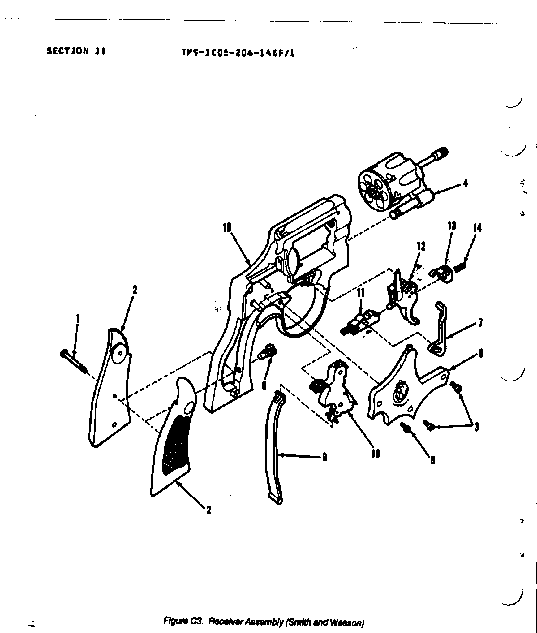
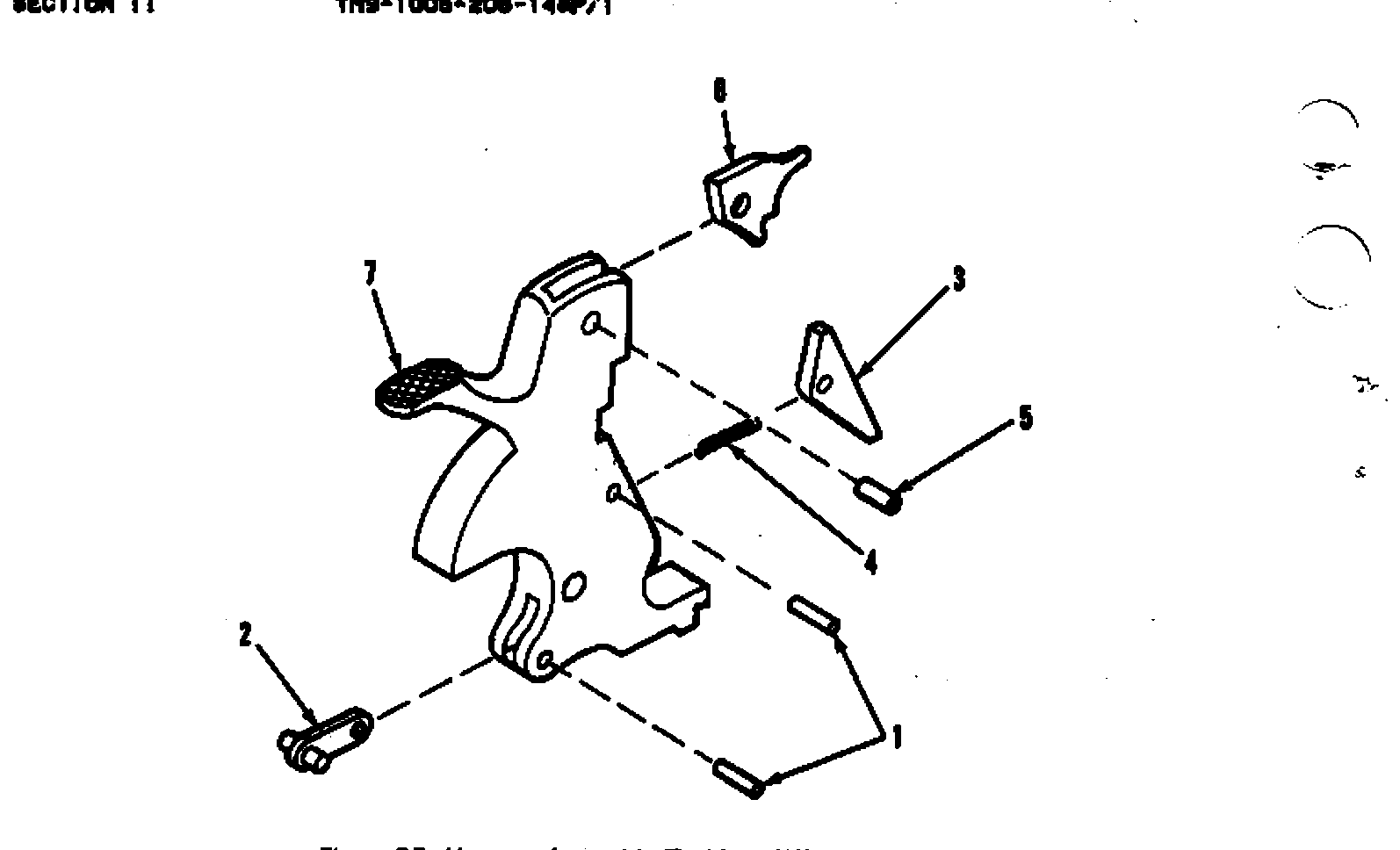
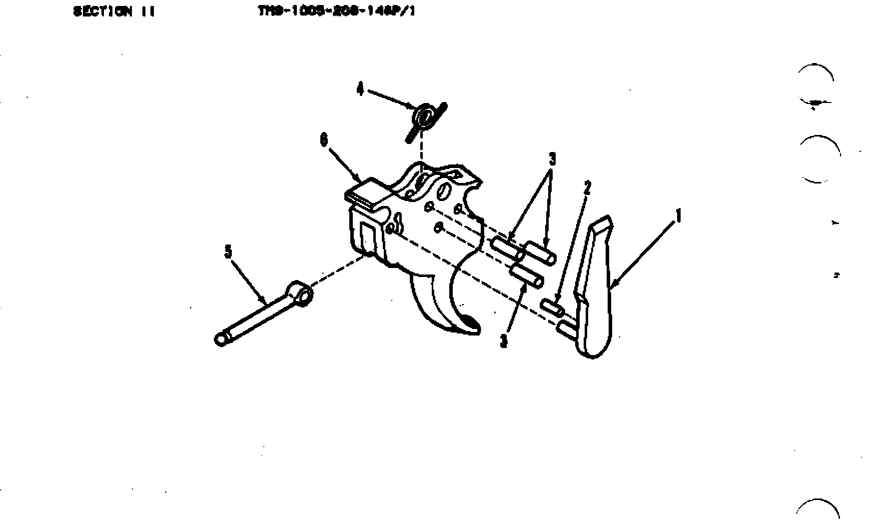
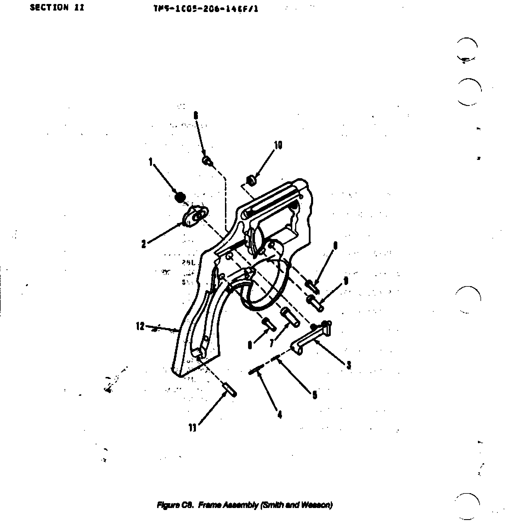
Parts: 53 numbered parts (complete revolver per the Smith & Wesson section of the Army RPSTL (Figures C1-C8, Groups 00-0206): every piece-part item number, with the assembly headers (C1-2, C1-3, C3-4, C3-10, C3-11, C3-12, C3-1), from TM 9-1005-206-14&P-1, Revolver, Caliber .38 Special: Smith and Wesson Military and Police M10 (and Ruger) - Appendix C, Section II Repair Parts List (archive.org OCR text of the scanned PDF) — Headquarters, Department of the Army (scan hosted by archive.org), PDF pp. 98-108 (C1-1 to C8-1) archive.org [8].
Bench time: about 35 min to strip, 55 min to rebuild (estimate). Estimated for an experienced tech with the right tools: grips, sideplate, lockwork, crane/cylinder, thumbpiece/bolt, locking bolt and sights. Rebuild is longer for the rebound slide spring, hand spring engagement, hammer block and sideplate seating plus a timing/carry-up and end-shake check. The TM work-time figures (hours) are given as a cross-check, not as the job time.
Small parts: 9 pins, 9 springs, 1 detents or plungers (counted by name in the same list (C1-C8): pins = PIN, BARREL; PIN, LOCKING BOLT; PIN, CENTER/PIN, SHOULDER, HEADLESS (C4-6); PIN, EXTRACTOR; PIN, STRAIGHT, HEADLESS (C5-1, C7-3, C8-11); PIN, REBOUND S)
What comes off for coating
- Grips and sideplate: stock screw and stocks, sideplate screws (kept in their holes; the front one retains the crane), sideplate (tapped free, never pried), hammer block — fitted hollow-ground screwdrivers, nylon/brass or rawhide mallet
- Lockwork: mainspring and strain screw, rebound slide, rebound slide spring and pin, hammer (with sear, stirrup, hammer nose), trigger with hand and hand torsion spring, trigger lever, cylinder stop and cylinder stop spring, trigger stop rod (if fitted), internal-lock flag, spring and cam (IL guns) — rebound slide spring tool or small Phillips screwdriver
- Cylinder and crane: cylinder and yoke/crane out of the frame, extractor rod (left-hand thread) and center pin with springs if the cylinder is coated — padded vise or extractor-rod collar tool
- Frame: thumbpiece nut and thumbpiece, bolt, bolt plunger and spring, locking bolt, spring and pin (under the barrel), rear sight (adjustable models: leaf, elevation/windage parts, plunger and spring), front sight (pinned or plunger-retained on some models) — punch set, pin punch for sight and locking-bolt pins
Special tools
- Rebound slide spring tool (Brownells S&W tool) or a Phillips screwdriver just larger than the spring ID — Compressing and re-seating the rebound slide spring over its stud
- Fitted hollow-ground (gunsmith) screwdrivers — Sideplate, strain, thumbpiece and stock screws without burring
- Nylon/brass or rawhide mallet — Tapping the frame to lift a tight sideplate
- Large clear plastic bag — Containing the rebound spring and small springs on removal
Known pain points
- The rebound slide spring is under heavy tension; it launches when the slide is pried off and must be compressed back over its stud on reassembly. (both)
Source: Installing Smith & Wesson Spring Kit — Shooting Times shootingtimes.com [6] — “The best way to remove the rebound slide is to just pry it up a bit, but be aware that the spring is under considerable tension and could do real harm if it hit you in the wrong place.” - The hammer block lies loose under the sideplate and must be seated up on the rebound slide pin while the sideplate is fitted. (reassembly)
Source: Installing Smith & Wesson Spring Kit — Shooting Times shootingtimes.com [6] — “The hammer-block safety will be lying loose under it, so take care to note how it goes in. There is a small pin on the rebound slide where it rides.” - The hand must keep its torsion-spring tension when the trigger goes back in, or the cylinder will not index. (reassembly)
Owners report: Change of a 686 rebound spring — Smith & Wesson Forum smith-wessonforum.com [7] — “make certain you still have spring tension on the hand (some people accidentally pull the hand back too far when removing or installing the trigger, causing the internal stud on the hand to slip past the spring inside the trigger).” - The sideplate must be tapped off the frame, never pried, and the sideplate screws go back in the holes they came from. (disassembly)
Source: Installing Smith & Wesson Spring Kit — Shooting Times shootingtimes.com [6] — “It might seem logical to pry it off; however, that is absolutely the wrong way to do it and can damage the gun. Instead, tap gently on the frame just below the sideplate with a brass or nylon hammer, and it will pop right up and can be lifted off.” - Smith & Wesson tells owners not to go beyond the field strip; lockwork work is for a qualified gunsmith. (both)
Source: Safety & Instruction Manual, Revolvers - Modern Style - J, K, L and N Frame (p/n 416560000, REV S&W_REVOLVER_112119), linked from smith-wesson.com revolver product pages — Smith & Wesson smith-wesson.canto.com [2] — “NEVER DISASSEMBLE YOUR FIREARM beyond the field stripping procedure outlined in this manual. Improper disassembly or reassembly of your firearm may be dangerous and can lead to serious injury or death.”
Fit or check on rebuild
- Timing / carry-up: each chamber must lock before the hammer falls, single and double action — The hand torsion spring must engage the hand; a hand pulled back too far loses spring tension and the cylinder will not index.
Source: Change of a 686 rebound spring — Smith & Wesson Forum smith-wessonforum.com [7] — “make certain you still have spring tension on the hand (some people accidentally pull the hand back too far when removing or installing the trigger, causing the internal stud on the hand to slip past the spring inside the trigger).” - Cylinder gap (barrel-cylinder) and end shake; crane alignment — The Army issues gauges for exactly these checks when the cylinder/yoke group is replaced.
- Firing-pin (hammer-nose) protrusion and hammer-block function — Same TM lists a firing-pin protrusion gauge; the hammer block must ride up on the rebound slide pin before the sideplate goes on.
Source: Installing Smith & Wesson Spring Kit — Shooting Times shootingtimes.com [6] — “The hammer-block safety will be lying loose under it, so take care to note how it goes in. There is a small pin on the rebound slide where it rides.” - Sideplate seats flush with no forcing; strain screw fully tightened — A sideplate that is not flush binds the grips and parts behind it; a backed-out strain screw gives light strikes (well-known S&W check).
- Trigger reset with the rebound spring fitted — The rebound slide spring is also the trigger return spring.
Source: Installing Smith & Wesson Spring Kit — Shooting Times shootingtimes.com [6] — “The downside is that the rebound also serves as the trigger return spring”
This is Pew-Takedown's rating, not the manufacturer's. How tiers are rated. Forum reports are owners' experience, not specifications.
Manufacturer videos
Official videos from Smith & Wesson's own channels, linked rather than copied. Where a video and the steps on this page differ, follow the manufacturer's manual and video.
- How To Clean a Revolver | Smith & Wesson® Smith & Wesson
cleaning, maintenance · 2026-02-23
Covers: Revolvers in general (S&W's own generic guide; no model named in title/description) - Unloading & Reloading Revolvers Smith & Wesson
clearing, operation · 2021-07-13
Covers: Revolvers in general (GUNSMARTS series, Jerry Miculek; no model named)
Procedures
Clear and Make Safe
Clear & Make SafeManufacturer’s video: Unloading & Reloading Revolvers Smith & Wesson
- Point the muzzle in a safe direction and keep your finger off the trigger.
- Push the thumbpiece forward and swing the cylinder out to the left.
- Press the ejector rod firmly to eject all cartridges or cases from the chambers.TipPoint the muzzle up and strike the rod briskly with the palm so the cases clear fully.Removed at this step:
Cartridges or cases - Look through every chamber, one at a time, and confirm each is empty.WarningAll six. A revolver with one loaded chamber looks identical to an empty one from most angles.
- Confirm the chamber-to-barrel gap area and the bore are clear of obstruction.
- Remove all live ammunition from the work area.
Routine cleaning (what Smith & Wesson documents)
Field Strip tools requiredS&W's revolver manual publishes no takedown. This is the maintenance it does prescribe.
- Complete the Clear and Make Safe procedure and leave the cylinder swung out.
- Clean the bore and each chamber with a solvent-wetted patch and bronze brush, then dry patches until they come out clean.
- Clean the front face of the cylinder, the forcing cone, and the recoil shield, where fouling and lead build up fastest.
- Restrict your choice of solvent to products made for firearms, and avoid prolonged solvent immersion or ultrasonic cleaning — S&W records finish damage from both.WarningNever use ammoniated or other strong alkaline solvents on a Smith & Wesson.TipS&W's rule of thumb: if you would be happy putting it on your car's paint, it is probably safe on the gun.
- Come back in 24 to 48 hours. Residue works its way out of the barrel and chambers after the first clean; remove it with a bristle brush and a light re-application of solvent, then re-oil.
- Apply a light film of good gun oil to all external metal surfaces and wipe clean. In cold climates use an oil that will not thicken.
- Stop here. S&W publishes no disassembly procedure for this revolver and directs additional maintenance to a qualified gunsmith.
Remove the side plate and strip the lockwork
Detail Strip tools required gunsmith recommendedPara 6-11, 'Maintenance of Receiver Assembly' (S and W column): grips and cylinder/yoke off, side plate tapped free, then hammer block, mainspring, hammer, rebound slide, trigger assembly and cylinder stop. This goes past where the entry's Sideplate Removal procedure stops. TM 9-1005-206-14&P-1 assigns this to direct support maintenance (MAC column F; receiver-assembly repair also has a general support (H) allowance). Operator maintenance is limited to inspecting, lubricating, servicing and troubleshooting, and organizational maintenance to grips and minor hardware.
Follows TM 9-1005-206-14&P-1 Operator's, Organizational, Direct Support, and General Support Maintenance Manual Including Repair Parts and Special Tools List for Revolver, Caliber .38 Special: Smith and Wesson, Military and Police, M10 (Round Butt 4-inch and 2-inch Barrel; Square Butt 4-inch Barrel) and Rev — Headquarters, Department of the Army, para 6-11, pp. 6-18 to 6-23 archive.org [4]
- Remove the grip screw.WarningMake sure revolver is not loaded and barrel is not obstructed.TipOn the S&W the screw is removed from the side opposite the one shown in the manual's illustration.Removed at this step:
Grip screw - Remove both grips from the frame.Removed at this step:
Grips (2) - Press forward on the thumbpiece and open the cylinder.
- Remove the front side plate screw (yoke screw).Removed at this step:
Front side plate (yoke) screw - Carefully slide the cylinder assembly forward, lining up one of the flutes in the cylinder with the edge of the frame.
- Remove the cylinder and yoke assembly.Removed at this step:
Cylinder and yoke assembly - Remove the two remaining side plate screws.WarningDo not attempt to pry the side plate from the frame. Prying can damage the frame or side plate.Removed at this step:
Side plate screws (2) - Pad the frame around the side plate and gently tap the frame areas near the side plate with a soft-faced hammer, gradually lifting the side plate off.Removed at this step:
Side plate - Remove the hammer block.Removed at this step:
Hammer block - Remove the strain screw.Removed at this step:
Strain screw - Push the top of the flat (main) spring forward to take its strain off the stirrup, release it from the lugs on the stirrup, and remove it.Removed at this step:
Flat spring (mainspring) - Push the thumbpiece back and hold it, cock the hammer and hold the trigger to the rear.TipThe thumbpiece is on the left side of the revolver.
- Remove the hammer from the hammer stud and release the trigger.Removed at this step:
Hammer assembly - Carefully raise the rebound slide until it clears its stud, easing the tension on the compression spring.WarningAfter the rebound slide clears the stud, gradually ease tension on the compression spring to prevent it from being lost or damaged.
- Remove the rebound slide assembly, leaving the compression spring in its recess.Removed at this step:
Rebound slide assembly - Hold the hand to the rear and carefully lift the trigger assembly off the trigger stud on the frame.Removed at this step:
Trigger assembly - Remove the cylinder stop from the frame.Removed at this step:
Cylinder stop - Remove the stop spring from the cylinder stop.Removed at this step:
Cylinder stop spring
Disassemble the cylinder and yoke assembly
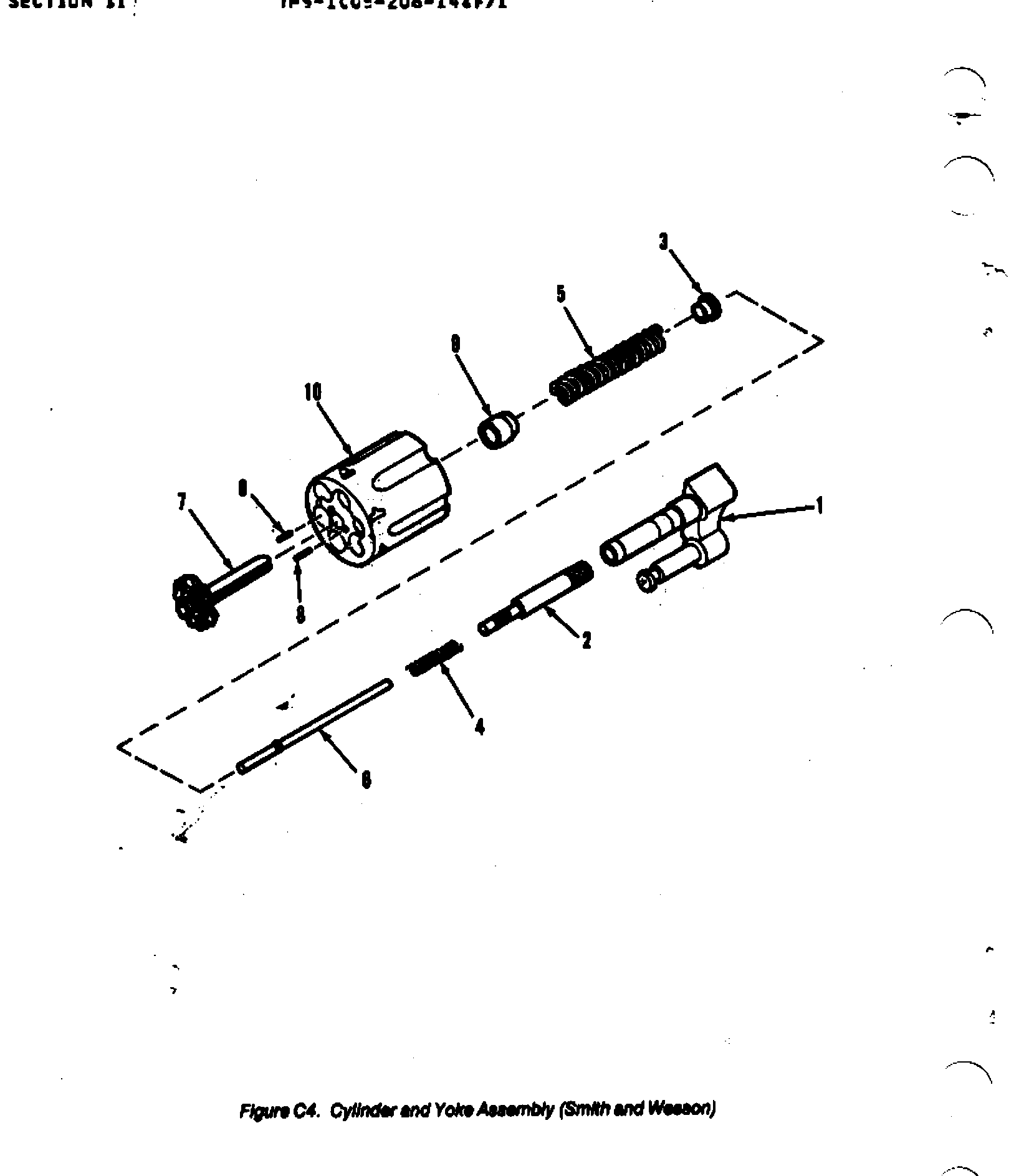
Detail Strip tools required gunsmith recommendedPara 6-13 (S and W column): yoke out of the cylinder, extractor rod (left-hand thread), collar, springs, center pin and extractor out; extractor pins and gas ring only for replacement. TM 9-1005-206-14&P-1 assigns this to direct support maintenance (MAC column F; receiver-assembly repair also has a general support (H) allowance). Operator maintenance is limited to inspecting, lubricating, servicing and troubleshooting, and organizational maintenance to grips and minor hardware.
Follows TM 9-1005-206-14&P-1 Operator's, Organizational, Direct Support, and General Support Maintenance Manual Including Repair Parts and Special Tools List for Revolver, Caliber .38 Special: Smith and Wesson, Military and Police, M10 (Round Butt 4-inch and 2-inch Barrel; Square Butt 4-inch Barrel) and Rev — Headquarters, Department of the Army, para 6-13, pp. 6-31 to 6-32 archive.org [4]
- Remove the cylinder and yoke assembly from the revolver.
- Slide the yoke out of the cylinder assembly.Removed at this step:
Yoke - Unscrew the extractor rod from the extractor.WarningThe threads on the end of the extractor rod and in the extractor are left-hand threads. Turn clockwise to loosen and counterclockwise to tighten.Removed at this step:
Extractor rod - Remove the extractor rod collar, the two compression springs, the center pin and the extractor from the cylinder.Removed at this step:
Extractor rod collarCompression springs (2)Center pinExtractor - Remove the extractor pins and the gas ring from the cylinder only if they are being replaced.WarningExtractor pins and gas ring must not be removed except for replacement.Removed at this step:
Extractor pinsGas ring
Disassemble the rebound slide
Detail Strip tools required gunsmith recommendedPara 6-15 (S and W only). TM 9-1005-206-14&P-1 assigns this to direct support maintenance (MAC column F; receiver-assembly repair also has a general support (H) allowance). Operator maintenance is limited to inspecting, lubricating, servicing and troubleshooting, and organizational maintenance to grips and minor hardware.
Follows TM 9-1005-206-14&P-1 Operator's, Organizational, Direct Support, and General Support Maintenance Manual Including Repair Parts and Special Tools List for Revolver, Caliber .38 Special: Smith and Wesson, Military and Police, M10 (Round Butt 4-inch and 2-inch Barrel; Square Butt 4-inch Barrel) and Rev — Headquarters, Department of the Army, para 6-15, p. 6-42 archive.org [4]
- Shake the compression spring out of the rebound slide.Removed at this step:
Rebound slide spring - Drive the rebound slide pin out of the rebound slide.Removed at this step:
Rebound slide pin
Disassemble the trigger assembly
Detail Strip tools required gunsmith recommendedPara 6-16 (S and W column): hand ('hand trigger') and hand pin, torsion spring, and trigger lever off the trigger. TM 9-1005-206-14&P-1 assigns this to direct support maintenance (MAC column F; receiver-assembly repair also has a general support (H) allowance). Operator maintenance is limited to inspecting, lubricating, servicing and troubleshooting, and organizational maintenance to grips and minor hardware.
Follows TM 9-1005-206-14&P-1 Operator's, Organizational, Direct Support, and General Support Maintenance Manual Including Repair Parts and Special Tools List for Revolver, Caliber .38 Special: Smith and Wesson, Military and Police, M10 (Round Butt 4-inch and 2-inch Barrel; Square Butt 4-inch Barrel) and Rev — Headquarters, Department of the Army, para 6-16, p. 6-43 archive.org [4]
- Pull up on the torsion spring and remove the hand and hand pin from the trigger.Removed at this step:
HandHand pin - Drive out the torsion spring's headless pin and remove the spring.Removed at this step:
Headless pinTorsion spring - Drive out the trigger lever's headless pins and remove the trigger lever from the trigger.Removed at this step:
Headless pinsTrigger lever
Remove the thumbpiece and cylinder bolt from the frame
Detail Strip tools required gunsmith recommendedPara 6-17, 'Maintenance of Frame Assembly' (S and W column), step 1, done with the lockwork already out. The manual's later frame steps (frame lug, brazed studs, bushing) are depot-style repairs and are left out. TM 9-1005-206-14&P-1 assigns this to direct support maintenance (MAC column F; receiver-assembly repair also has a general support (H) allowance). Operator maintenance is limited to inspecting, lubricating, servicing and troubleshooting, and organizational maintenance to grips and minor hardware.
Follows TM 9-1005-206-14&P-1 Operator's, Organizational, Direct Support, and General Support Maintenance Manual Including Repair Parts and Special Tools List for Revolver, Caliber .38 Special: Smith and Wesson, Military and Police, M10 (Round Butt 4-inch and 2-inch Barrel; Square Butt 4-inch Barrel) and Rev — Headquarters, Department of the Army, para 6-17, p. 6-47 archive.org [4]
- Remove the thumbpiece nut and the thumbpiece from the side of the frame.WarningBe careful not to bend or damage the bolt. Do not lose the plunger or spring.Removed at this step:
Thumbpiece nutThumbpiece - Slide the bolt to the rear and lift the back of the bolt up and out of the frame.Removed at this step:
Bolt - Remove the bolt plunger and helical spring from the bolt.Removed at this step:
Bolt plungerBolt spring
Reassemble the lockwork and install the side plate
Detail Reassembly tools required gunsmith recommendedPara 6-11 reassembly (S and W column), finishing with the manual's function tests. TM 9-1005-206-14&P-1 assigns this to direct support maintenance (MAC column F; receiver-assembly repair also has a general support (H) allowance). Operator maintenance is limited to inspecting, lubricating, servicing and troubleshooting, and organizational maintenance to grips and minor hardware.
Follows TM 9-1005-206-14&P-1 Operator's, Organizational, Direct Support, and General Support Maintenance Manual Including Repair Parts and Special Tools List for Revolver, Caliber .38 Special: Smith and Wesson, Military and Police, M10 (Round Butt 4-inch and 2-inch Barrel; Square Butt 4-inch Barrel) and Rev — Headquarters, Department of the Army, para 6-11, pp. 6-24 to 6-29 archive.org [4]
- Place the compression spring in the cylinder stop, depress the spring, and install the cylinder stop on the frame.
- Install the trigger assembly on its mounting stud by moving the hand to the rear and pivoting the trigger lever up.
- Hold the trigger and the thumbpiece to the rear, pivot the stirrup upward, and install the hammer on its stud.
- Make sure the compression spring is in the recess of the rebound slide.
- Depress the spring and install the rebound slide, beveled end forward, so the rear of the trigger lever fits in the recess of the rebound slide and against the retaining stud.
- Keep steady pressure on the compression spring until it is safely positioned against its stud.
- Install the flat (main) spring by attaching it to the stirrup and placing it into the frame.
- Install and tighten the strain screw.
- Install the hammer block.
- Check that the hammer block is positioned correctly, then install the side plate and seat it properly in the frame.
- Install the round-head and flat-head side plate screws.
- Line up the cylinder assembly with the frame and install it.
- Secure the cylinder assembly with its screw.
- Close the cylinder.
- Position the grips on the frame and secure them with the grip screw.
- Test hammer nose protrusion, cylinder alignment and trigger pull.TipManual values: hammer nose protrusion 0.040-0.050 inch; single-action pull 2 1/2 to 5 lb; double-action pull not over 16 lb.
Reassemble the cylinder and yoke assembly
Detail Reassembly tools required gunsmith recommendedPara 6-13 reassembly (S and W column). TM 9-1005-206-14&P-1 assigns this to direct support maintenance (MAC column F; receiver-assembly repair also has a general support (H) allowance). Operator maintenance is limited to inspecting, lubricating, servicing and troubleshooting, and organizational maintenance to grips and minor hardware.
Follows TM 9-1005-206-14&P-1 Operator's, Organizational, Direct Support, and General Support Maintenance Manual Including Repair Parts and Special Tools List for Revolver, Caliber .38 Special: Smith and Wesson, Military and Police, M10 (Round Butt 4-inch and 2-inch Barrel; Square Butt 4-inch Barrel) and Rev — Headquarters, Department of the Army, para 6-13, pp. 6-37 to 6-38 archive.org [4]
- If they were removed, drive a new gas ring into the cylinder.
- If they were removed, drive new extractor pins into the cylinder.
- Insert the extractor, compression spring, extractor rod collar, center pin and second compression spring in the cylinder.
- Insert the extractor rod in the extractor and tighten it.WarningThe threads on the end of the extractor rod and in the extractor are left-hand threads. Turn counterclockwise to tighten or install.
- Slide the yoke into the cylinder.
Reassemble the rebound slide
Detail Reassembly tools required gunsmith recommendedPara 6-15 (S and W only). TM 9-1005-206-14&P-1 assigns this to direct support maintenance (MAC column F; receiver-assembly repair also has a general support (H) allowance). Operator maintenance is limited to inspecting, lubricating, servicing and troubleshooting, and organizational maintenance to grips and minor hardware.
Follows TM 9-1005-206-14&P-1 Operator's, Organizational, Direct Support, and General Support Maintenance Manual Including Repair Parts and Special Tools List for Revolver, Caliber .38 Special: Smith and Wesson, Military and Police, M10 (Round Butt 4-inch and 2-inch Barrel; Square Butt 4-inch Barrel) and Rev — Headquarters, Department of the Army, para 6-15, p. 6-42 archive.org [4]
- Drive the rebound slide pin into the rebound slide until it is flush with the back side of the slide.
- Insert the compression spring into the rebound slide.
Reassemble the trigger assembly
Detail Reassembly tools required gunsmith recommendedPara 6-16 reassembly (S and W column). TM 9-1005-206-14&P-1 assigns this to direct support maintenance (MAC column F; receiver-assembly repair also has a general support (H) allowance). Operator maintenance is limited to inspecting, lubricating, servicing and troubleshooting, and organizational maintenance to grips and minor hardware.
Follows TM 9-1005-206-14&P-1 Operator's, Organizational, Direct Support, and General Support Maintenance Manual Including Repair Parts and Special Tools List for Revolver, Caliber .38 Special: Smith and Wesson, Military and Police, M10 (Round Butt 4-inch and 2-inch Barrel; Square Butt 4-inch Barrel) and Rev — Headquarters, Department of the Army, para 6-16, p. 6-45 archive.org [4]
- Insert the trigger lever in the trigger and secure it with its headless pin.
- Insert the second headless pin.
- Install the torsion spring and secure it with its headless pin.
- Drive the hand pin into the hand.
- Pull up on the torsion spring and install the hand so that the hand pin engages the torsion spring.
Install the cylinder bolt and thumbpiece
Detail Reassembly tools required gunsmith recommendedPara 6-17 reassembly (S and W column), steps 8-10. TM 9-1005-206-14&P-1 assigns this to direct support maintenance (MAC column F; receiver-assembly repair also has a general support (H) allowance). Operator maintenance is limited to inspecting, lubricating, servicing and troubleshooting, and organizational maintenance to grips and minor hardware.
Follows TM 9-1005-206-14&P-1 Operator's, Organizational, Direct Support, and General Support Maintenance Manual Including Repair Parts and Special Tools List for Revolver, Caliber .38 Special: Smith and Wesson, Military and Police, M10 (Round Butt 4-inch and 2-inch Barrel; Square Butt 4-inch Barrel) and Rev — Headquarters, Department of the Army, para 6-17, p. 6-52 archive.org [4]
- Insert the helical spring and bolt plunger in the end of the bolt and compress the spring.
- With the spring fully compressed, insert the bolt in the frame.
- Install the thumbpiece and secure it with the thumbpiece nut.
Reassembly
Reassembly- Slide the yoke and cylinder assembly back into the frame, seating the yoke fully in its frame cut.
- Start the yoke retaining screw by hand to avoid cross-threading, then tighten it snugly with the correct screwdriver.WarningDo not overtighten. The screw only needs to be snug; it is not a structural fastener.
- Close the cylinder gently by hand. Never flick it closed.WarningFlicking the cylinder closed springs the crane and puts the revolver out of time.
- Perform the function check.
Diagrams
public domainThese are reproduced from government technical manuals, which are not subject to copyright. Manufacturer manual diagrams are not reproduced here — the entry links to the manual instead.
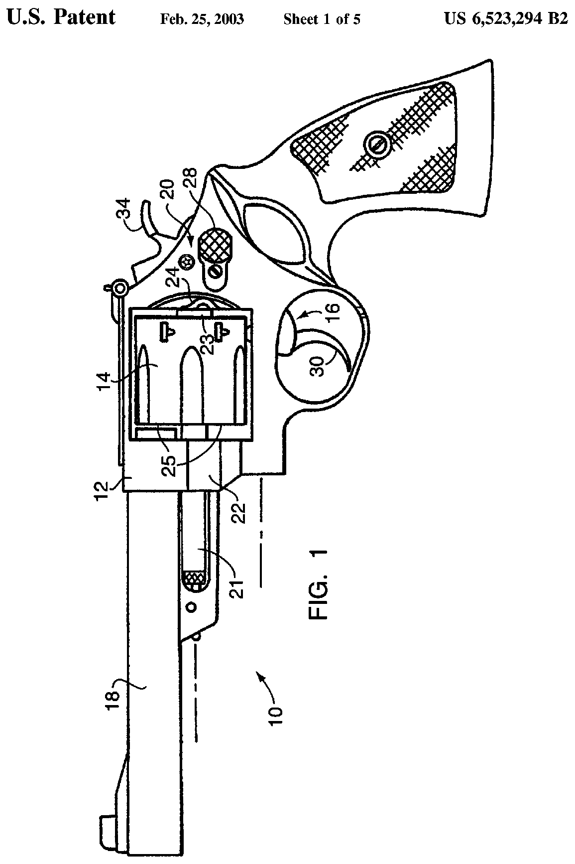
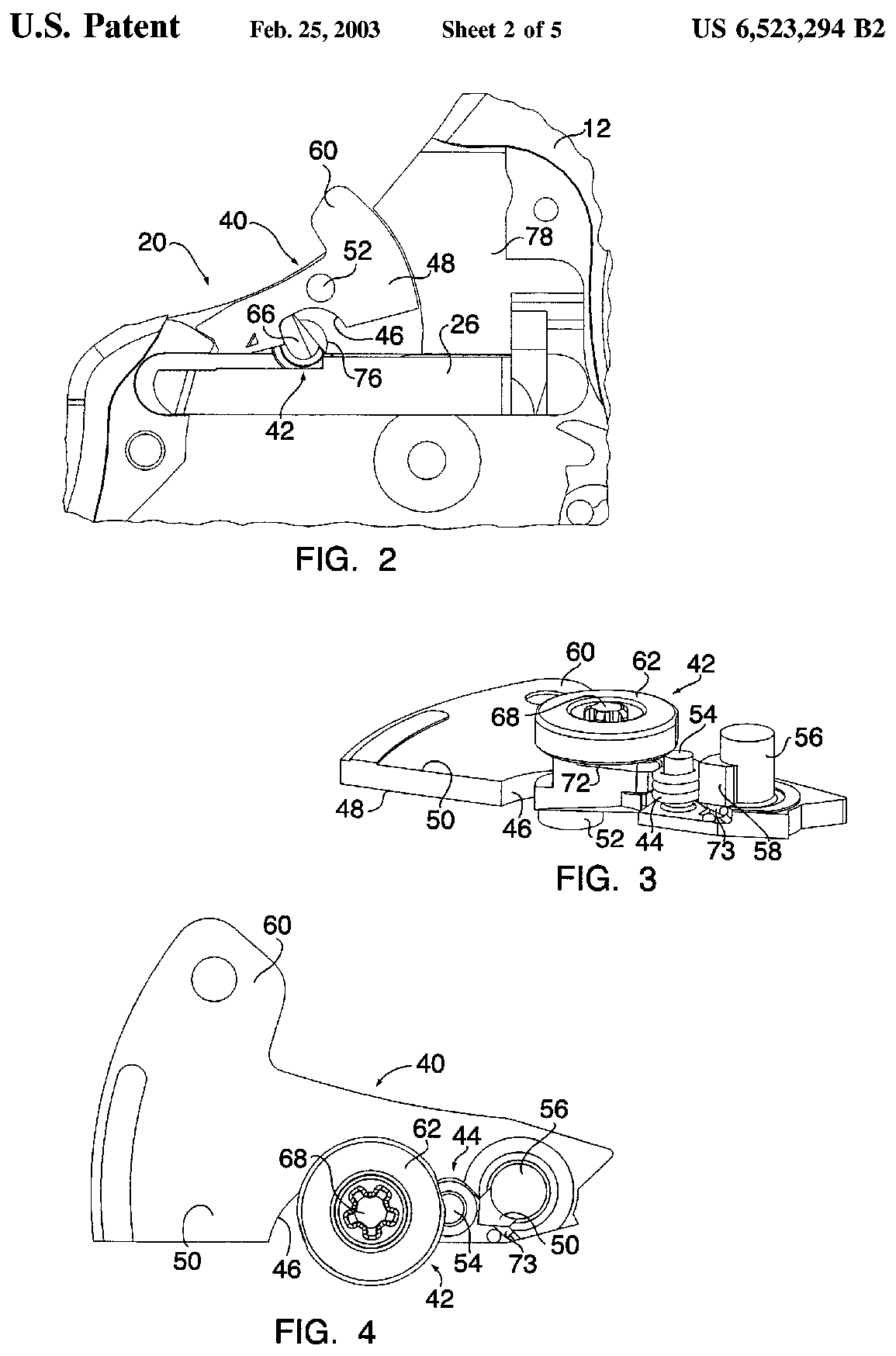
Patent drawings
not under copyrightDrawings from US patents on this design. A patent shows the invention as the inventor filed it; the firearm that shipped can differ in detail, and later production often does. Use them to see how the parts relate, not as a parts reference or a procedure. Per the USPTO, the text and drawings of a patent are typically not subject to copyright; each patent here was checked for a copyright notice.
US Patent 6,523,294 — Revolver-safety lock mechanism
Brett Curry, Owen Patrick Cramer, Richard F. Mikuta, James M. Quill, Kevin R. Fleury · assigned to Smith & Wesson Corp. · filed 2001-04-12 · granted 2003-02-25. Full patent (USPTO)
The internal key-lock (lockarm and actuator) built into the frame of S&W revolvers, shown on a side view of a S&W revolver and in partial section at the hammer. Applies only to revolvers built with the internal lock.
Why this is the Smith & Wesson Model 10’s patent: listed on the maker’s patent-marking page — Virtual Patent Marking | Smith & Wesson — Smith & Wesson smith-wesson.com [5]: “6,523,294 All S&W® revolvers with internal locks”
Torque specifications
No sourced torque values from the manufacturer are recorded for this firearm. Where a fastener has a specified torque — action screws, scope bases, muzzle devices, barrel nuts — get it from the manufacturer or a gunsmith rather than estimating it.
What the manufacturer does say: The manufacturer's documents give no torque value. They say: "The barrel assembly is re-installed using the same tool and an accurate torque wrench." (Safety & Instruction Manual, Revolvers - Modern Style - J, K, L and N Frame (p/n 416560000, REV S&W_REVOLVER_112119), linked from smith-wesson.com revolver product pages, p. 26 (Gunsmith Advisory))
Materials and factory finish
As stated by Smith & Wesson. Prep, masking and cure depend on these; a polymer or aluminium part, a nitrided or anodised finish, and a blued steel part are each a different job. Variants with other finishes may exist — check the maker's page for the exact SKU on the bench.
| Component | Material | Factory finish | Where it comes from |
|---|---|---|---|
| Frame Model 10 Classic, 4in, no internal lock, SKU 14074 | CARBON STEEL | BLUED | Smith & Wesson Model 10 Classic (No Internal Lock) — product specifications, SKU 14074 — Smith & Wesson Brands, Inc. smith-wesson.com [3] “FRAME MATERIAL … CARBON STEEL … COLOR/FINISH … BLUED” |
| Grips Model 10 Classic, 4in, no internal lock, SKU 14074 | WALNUT | — | Smith & Wesson Model 10 Classic (No Internal Lock) — product specifications, SKU 14074 — Smith & Wesson Brands, Inc. smith-wesson.com [3] “GRIP … WALNUT” |
Parts
No parts list from Smith & Wesson is transcribed for this firearm.
Smith & Wesson's own documents label the parts on these pages — the links open each document at the page:
- Model and features identification (labelled photo of the revolver): Smith & Wesson Revolvers (Modern Style) Safety & Instruction Manual — Smith & Wesson, p. 14 mcarbo.com [1]
Function check
- Verify all chambers are empty before each check.
- Cock the hammer slowly and confirm the cylinder locks up at each chamber before the hammer reaches full cock — this is carry-up.
- With the hammer at full cock, try to rotate the cylinder by hand. It should be locked, with only minimal play.
- Press the trigger in single action and confirm the hammer falls cleanly.
- Cycle the action in double action through all six chambers and confirm the cylinder indexes and locks each time.
- Confirm the cylinder latches closed securely and the thumbpiece releases it cleanly.
- Check that the cylinder has minimal front-to-back play (endshake) and that the cylinder gap looks even. If either seems off, see a gunsmith.
Maintenance
Lubrication points
- Yoke barrel where the cylinder rides
- Ejector rod
- Hammer and trigger pivot pins (a single drop each)
- Cylinder stop
Cleaning notes
Lead and carbon build up on the front face of the cylinder and in the forcing cone. Left alone they eventually bind the cylinder. Clean the chambers thoroughly — a fouled chamber makes extraction difficult and is often mistaken for a timing problem. Keep lubrication sparing; a revolver's lockwork does not want to be wet.
Suggested inspection interval: roughly every 2000 rounds. This is a general guideline, not a manufacturer specification.
Wear parts to inspect
Hand · Cylinder stop · Ejector rod (check it has not unscrewed) · Forcing cone (inspect for cracks) · Yoke alignment
Common issues
| Symptom | Likely cause | What to do |
|---|---|---|
| Cylinder binds or the action locks up mid-shooting | Ejector rod backing out under recoil, or carbon and lead fouling on the cylinder face | Check the ejector rod is tight, and clean the cylinder face and forcing cone. |
| Cylinder does not lock up before the hammer falls | Worn hand or cylinder stop — a timing problem | Stop shooting the revolver. Firing out of time can shave lead sideways out of the cylinder gap. see a gunsmith |
| Difficult extraction of fired cases | Fouled or rough chambers, or high-pressure loads | Clean the chambers thoroughly with a bronze brush. If it persists, have the chambers inspected. see a gunsmith |
| Cylinder will not close | A high primer on a chambered round, a bent ejector rod, or a sprung crane from flicking the cylinder closed | Unload and inspect. A bent rod or sprung crane needs a gunsmith. see a gunsmith |
Also covers
The procedures above are reported to apply to: Smith & Wesson Model 15 · Model 64 · Model 67 · Most S&W K-frame and J-frame double-action revolvers. Verify against the manual for your specific model.
Similar manual of arms
Sourcing
- Confidence
- medium — Drawn from reliable secondary sources and consistent across references, but not confirmed against a primary source.
- Verification
- Checked against the manufacturer manual
- Last updated
- 2026-10-29
References
Every source this page draws on, with its web address so you can read it yourself. Numbers in brackets elsewhere on the page point here.
- [1] Smith & Wesson Revolvers (Modern Style) Safety & Instruction Manual — Smith & Wesson manufacturer manual primary source
https://www.mcarbo.com/.Owners%20Manuals/S-W_Revolver_Owners-Manual.pdf (checked 2026-09-15) - [2] Safety & Instruction Manual, Revolvers - Modern Style - J, K, L and N Frame (p/n 416560000, REV S&W_REVOLVER_112119), linked from smith-wesson.com revolver product pages — Smith & Wesson manufacturer manual primary source
https://smith-wesson.canto.com/direct/document/tquc8lb05d2hl96gi51fuh2m46/2Ppiam-m3ty8iZtHw_DoQfTzAsI/original?content-type=application%2Fpdf (checked 2026-09-27) - [3] Smith & Wesson Model 10 Classic (No Internal Lock) — product specifications, SKU 14074 — Smith & Wesson Brands, Inc. website primary source
https://www.smith-wesson.com/product/model-10-classic-no-internal-lock (checked 2026-10-03) - [4] TM 9-1005-206-14&P-1 Operator's, Organizational, Direct Support, and General Support Maintenance Manual Including Repair Parts and Special Tools List for Revolver, Caliber .38 Special: Smith and Wesson, Military and Police, M10 (Round Butt 4-inch and 2-inch Barrel; Square Butt 4-inch Barrel) and Rev — Headquarters, Department of the Army (1985) military technical manual primary source
https://archive.org/download/revolver-cal-.-38-spl-smith-and-wesson-mil.-and-police-m-10/Revolver%2C%20Cal%20.38%20Spl%2C%20Smith%20and%20Wesson%20Mil.%20and%20Police%20M10.pdf (checked 2026-10-03) - [5] Virtual Patent Marking | Smith & Wesson — Smith & Wesson website primary source
https://www.smith-wesson.com/company/virtual-patent-marking (checked 2026-10-13) - [6] Installing Smith & Wesson Spring Kit — Shooting Times website secondary source
https://www.shootingtimes.com/editorial/gunsmithing_st_installswspringkit_200812/100181 (checked 2026-10-29) - [7] Change of a 686 rebound spring — Smith & Wesson Forum community anecdotal source
https://smith-wessonforum.com/threads/change-of-a-686-rebound-spring.330582 (checked 2026-10-29) - [8] TM 9-1005-206-14&P-1, Revolver, Caliber .38 Special: Smith and Wesson Military and Police M10 (and Ruger) - Appendix C, Section II Repair Parts List (archive.org OCR text of the scanned PDF) — Headquarters, Department of the Army (scan hosted by archive.org) military technical manual primary source
https://archive.org/download/revolver-cal-.-38-spl-smith-and-wesson-mil.-and-police-m-10/Revolver%2C%20Cal%20.38%20Spl%2C%20Smith%20and%20Wesson%20Mil.%20and%20Police%20M10_djvu.txt (checked 2026-10-29)
Notes: CORRECTED on 2026-09-15. The entry claimed manufacturer-manual verification while citing nothing, and presented yoke and cylinder removal as the routine field strip. Smith & Wesson's revolver manual publishes no disassembly procedure at all — its maintenance section is cleaning only, and it directs anything further to a qualified gunsmith. The routine procedure is now S&W's own cleaning sequence and the yoke removal is recorded as a detail strip labelled as unsanctioned practice. Confidence is medium, not high, for two reasons: this manual covers S&W revolvers generally rather than the Model 10 specifically, and the only copy reachable from here is a third-party mirror rather than a Smith & Wesson URL. The first mirror found was HTTP-only and the repository's own rule rejected it, so an HTTPS copy of the same document is cited instead — confirmed to carry the same cleaning guidance verbatim. Cylinder and yoke removal is owner-level and documented in the factory manual. Anything inside the sideplate is armorer or gunsmith work, and this entry deliberately stops short of describing lockwork adjustment. The detail procedures follow the US Army maintenance manual for the M10 (TM 9-1005-206-14&P-1, 1985), which assigns them to direct support; they replace an earlier community-practice sideplate procedure. Smith & Wesson itself publishes nothing past cleaning.