← All firearms · Printable work order
Smith & Wesson M&P15
- easy
- Shop tier 2
- high confidence
- Rifle
- direct impingement
- modular
- toolless field strip
- budget ar
field strip ~2 min · reassembly ~3 min · detail strip ~25 min
Specifications
- Manufacturer
- Smith & Wesson
- Origin
- United States
- Category
- Rifle
- Action
- Gas, direct impingement
- Calibers
- 5.56x45mm NATO, .223 Remington
- Capacity
- 30+1
- Production
- 2006–present (in-production)
- Also known as
- M&P15 Sport II
Model-specific safety
- The bolt cam pin MUST be installed. Without it the bolt cannot lock into the barrel extension, and firing in that condition can destroy the rifle and seriously injure the shooter. The firing pin retaining pin will not install without the cam pin in place — that is a designed safeguard, so if the retaining pin will not go in, stop and find out why.
- The safety selector only engages when the hammer is cocked. If it will not rotate to SAFE, the hammer is down.
- The buffer and buffer spring are under compression. When you depress the buffer retainer, control the buffer.
- Gas system components are extremely hot immediately after firing.
Under spring tension
- Buffer and buffer spring in the receiver extension
- Extractor spring
- Magazine springs
Easily lost parts
Bolt cam pin · Firing pin retaining pin · Extractor pin · Buffer retainer and spring
Tools
No tools required for the field strip.
Shop difficulty
Shop tier 2 Tier 2 — moderate among rifles and carbines, for the full job: strip to the parts that get coated and put it back together working. A mil-spec-pattern AR-15, so it has the same full-strip traps as the AR-556: captive pivot and takedown detents, the buffer retainer, the selector detent, roll pins, and a hammer spring that only goes one way.
Parts: 131 numbered parts (stand-in: Colt AR15-A2 Sporter (civilian semi-automatic AR-15, same mil-spec AR-15 receiver/bolt/fire-control pattern as the M&P15) per the Gun Digest exploded drawing legend, keys 1-131, complete rif), from The Gun Digest Book of Exploded Gun Drawings (975 isometric views) — Colt 'AR15-A2 Sporter Autoloading Rifle' — Gun Digest Books / Krause Publications (scan on archive.org), p. book p. 578 (PDF page 579) archive.org [9].
Bench time: about 45 min to strip, 70 min to rebuild (estimate). Full AR strip, same scope as the AR-556.
Small parts: 22 pins, 22 springs, 9 detents or plungers (counted by name in the same legend (line items). Pins: 3, 5 cam, 6 firing pin retaining, 15, 18 extractor pins, 29, 32, 36, 42, 45, 52, 66, 69 front sight taper pins, 80, 86, 95, 101, 110, 113, 114 ta)
What comes off for coating
- Upper: handguard / delta ring or rail, gas block and gas tube, front sight (if fitted), flash hider, forward assist, ejection port cover and pin — armorer's wrench
- Bolt carrier group: firing pin retaining pin, firing pin, cam pin, bolt, extractor pin, extractor, spring, ejector roll pin, ejector, spring
- Lower: buffer, buffer spring, buffer retainer and spring, castle nut / stock, pistol grip (selector detent and spring), selector, hammer, trigger, disconnector and springs, bolt catch roll pin, bolt catch, plunger, spring, magazine catch, trigger guard roll pin, front pivot pin and detent, rear takedown pin and detent — roll pin punches, vise block
Special tools
- AR armorer's wrench — Castle nut, muzzle device
- vise blocks — Receivers
- roll pin punches — Bolt catch, trigger guard, gas block pins
- pivot pin detent tool — Front pivot pin detent
Known pain points
- The front pivot-pin detent and spring launch during install without a pivot-pin tool. (reassembly)
Source: DIY AR-15 Build: Pivot Pin Installation — ITS Tactical itstactical.com [7] — “WARNING: The Pivot Pin Spring and Detent can launch out during this section and if you lose them you’d better have good eyes or you’ll be ordering replacements!” - A reversed hammer spring looks seated but does not detent the trigger pin. (reassembly)
Source: (Gunsmithing the AR-15 #2) The 30-Second AR Check — Gun Tests gun-tests.com [8] — “A hammer spring installed backwards will give a light primer strike causing misfires, and although it may appear to be laying on and detenting the trigger pin, it in fact will not.” - S&W stops the owner at the extractor. Anything further is factory or gunsmith work, so there is no maker procedure for the lower. (both)
Source: Safety & Instruction Manual for Centerfire Semi-Automatic Rifles including Volunteer Series & Sport Series (p/n 3015611, REV S&W_M&P_CF_MSR_REV_022724, © 2024), linked from smith-wesson.com/products/mp-15-sport-iii — Smith & Wesson smith-wesson.canto.com [3] — “CHANGES NOT COVERED IN THIS MANUAL OR IN A SMITH & WESSON INSTRUCTION SHEET WILL REQUIRE A QUALIFIED GUNSMITH (OR FACTORY-TRAINED PERSONNEL) USING FACTORY-AUTHORIZED PARTS.”
Fit or check on rebuild
- Hammer spring orientation and pins flush — A reversed spring will not detent the trigger pin.
Source: (Gunsmithing the AR-15 #2) The 30-Second AR Check — Gun Tests gun-tests.com [8] — “Hammer spring is correctly installed with both legs horizontal, spread out against inside wall of receiver, and laying on top of trigger in properly in the at pin’s outboard groove, acting as a detent for same.” - Function check (safety, trigger reset, feeding, extraction) — Standard after any detail strip. No single source.
- Re-zero sights or scope — Sights and optics come off for coating, and point of impact must be re-confirmed. This is a standard check, so no source.
This is Pew-Takedown's rating, not the manufacturer's. How tiers are rated. Forum reports are owners' experience, not specifications.
Manufacturer videos
Official videos from Smith & Wesson's own channels, linked rather than copied. Where a video and the steps on this page differ, follow the manufacturer's manual and video.
- Field Stripping Your Modern Sporting Rifle Smith & Wesson
field strip, cleaning · 2021-07-06
Covers: M&P15 (per description: 'a M&P®15 Modern Sporting Rifle')
Procedures
Clear and Make Safe
Clear & Make Safe- Point the muzzle in a safe direction and keep your finger off the trigger.
- Press the magazine release and remove the magazine.Removed at this step:
Magazine - Pull the charging handle fully to the rear and lock the bolt back with the bolt catch.
- Visually inspect the chamber and magazine well, then physically feel the chamber to confirm it is empty.WarningCheck the magazine well as well as the chamber — a round can hang up there.
- If the hammer is cocked, place the selector on SAFE.
- Remove all live ammunition from the work area.
Field Strip
Field StripManufacturer’s video: Field Stripping Your Modern Sporting Rifle Smith & Wesson
- Complete the Clear and Make Safe procedure and release the bolt forward.
- Push the rear takedown pin from the left side until it stops in its captured position.TipIf tight, tap it with a punch or a case rim rather than levering it.
- Pivot the upper receiver forward on the front pivot pin.
- Push the front pivot pin out to its captured position and separate the upper from the lower receiver.Removed at this step:
Upper receiver assembly - Pull the charging handle partway rearward and withdraw the bolt carrier group.Removed at this step:
Bolt carrier group - Pull the charging handle down and out of its channel.WarningThe charging handle comes out after the carrier, never before.Removed at this step:
Charging handle
Reassembly
Reassembly- Insert the bolt into the carrier with the extractor oriented toward the ejection port side.
- Push the bolt fully into the carrier, drop the cam pin into its hole, and rotate it 90 degrees.WarningIf the cam pin is not rotated, the firing pin will not seat. Never force the firing pin.
- Drop the firing pin into the rear of the carrier, tail first, and let it seat fully.
- Install the firing pin retaining pin. If it will not go in, the cam pin is missing or not rotated.WarningThis is the design’s built-in check. Do not defeat it.
- Insert the charging handle into its channel and push it partway forward.
- Insert the bolt carrier group into the charging handle’s track and slide both fully home.
- Mate the upper to the lower, press the front pivot pin home, close the receivers, and press the rear takedown pin home.
- Charge the rifle and perform the function check.
Diagrams
public domainThese are reproduced from government technical manuals, which are not subject to copyright. Manufacturer manual diagrams are not reproduced here — the entry links to the manual instead.
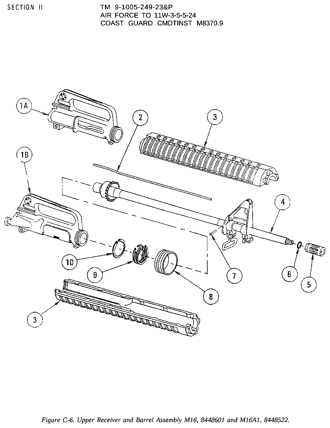
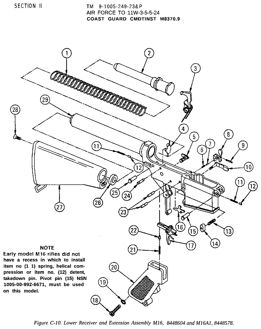
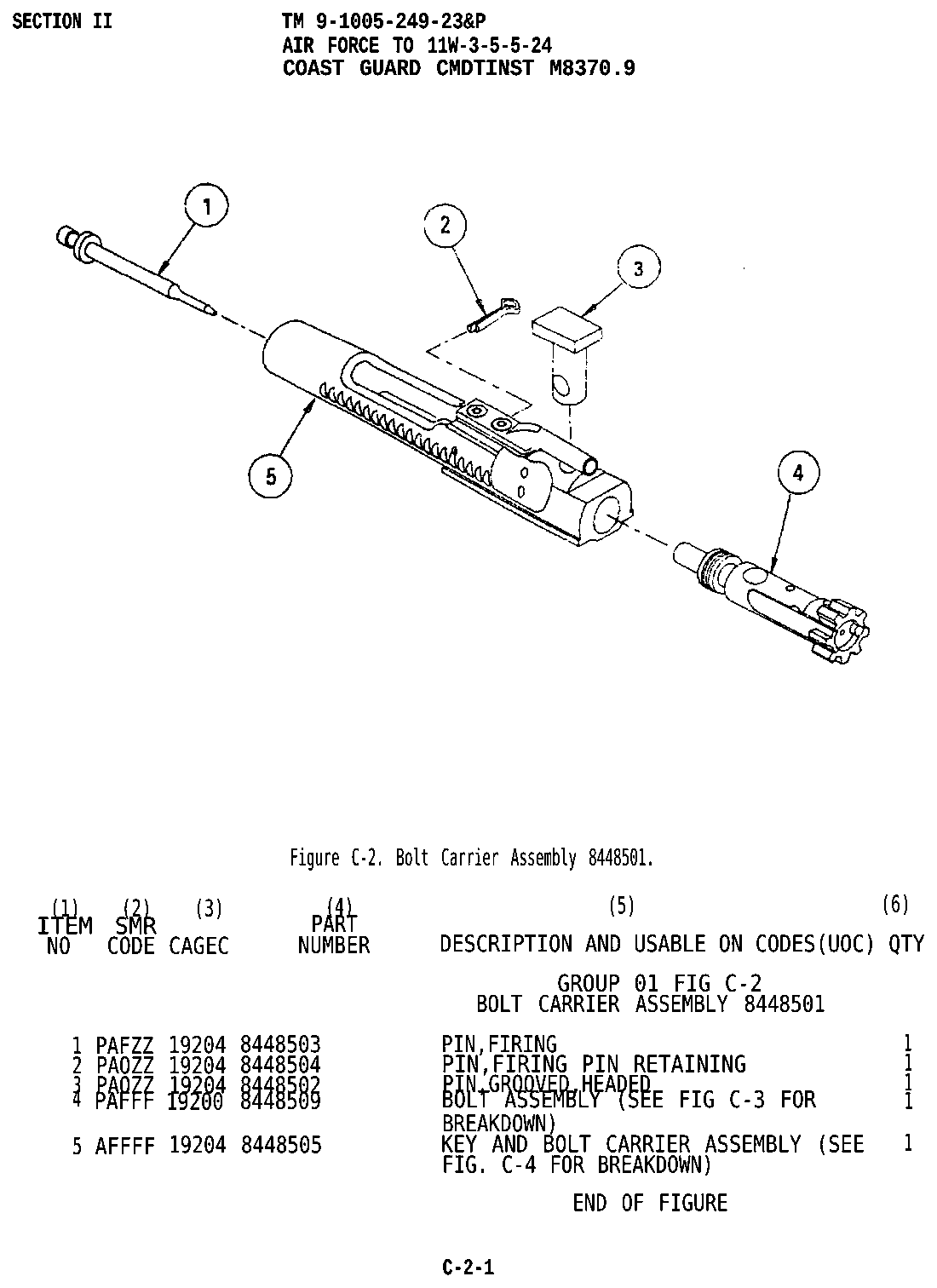
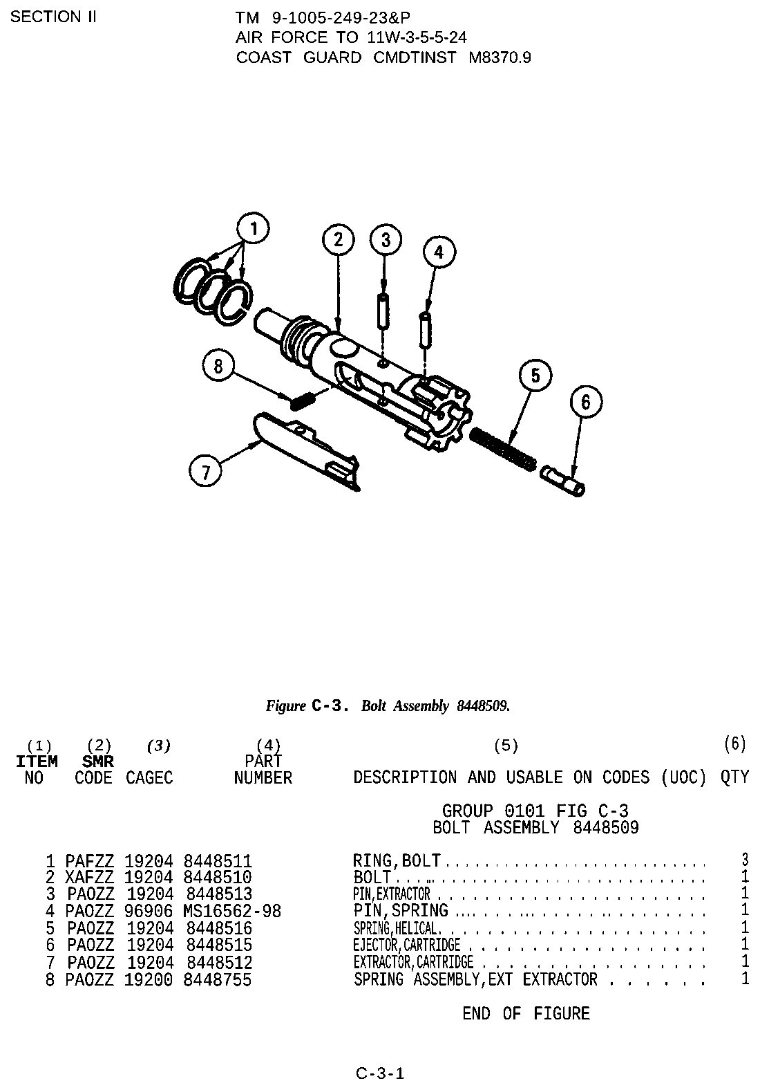
Patent drawings
not under copyrightDrawings from US patents on this design. A patent shows the invention as the inventor filed it; the firearm that shipped can differ in detail, and later production often does. Use them to see how the parts relate, not as a parts reference or a procedure. Per the USPTO, the text and drawings of a patent are typically not subject to copyright; each patent here was checked for a copyright notice.
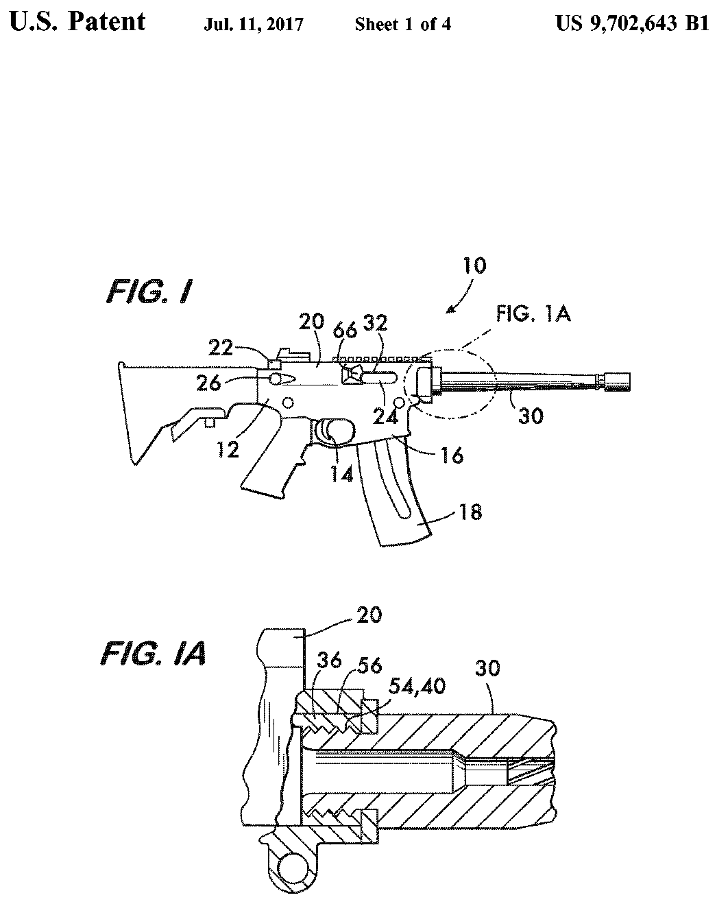
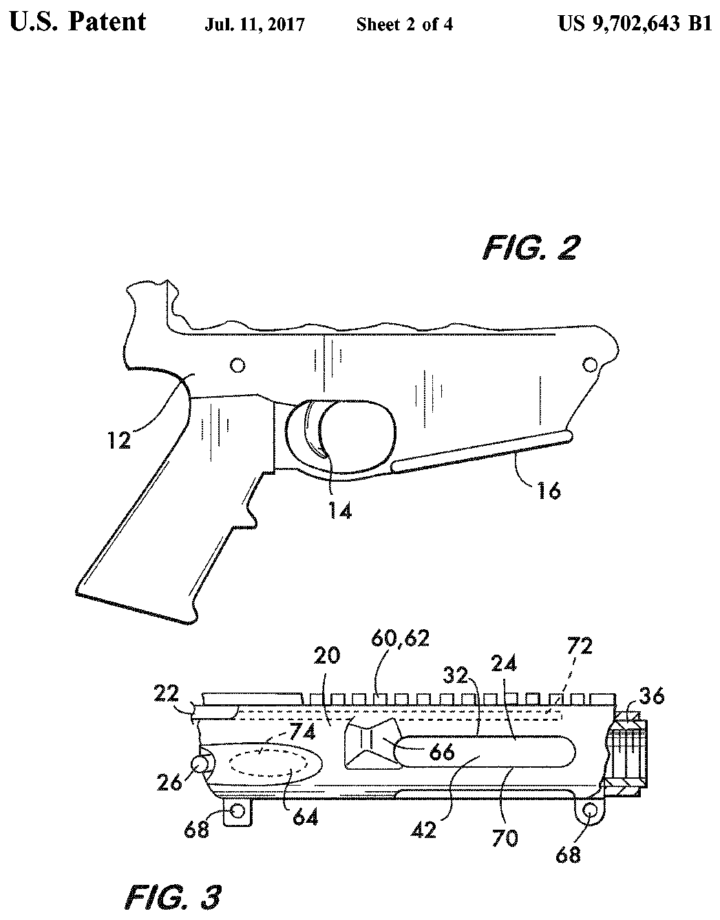
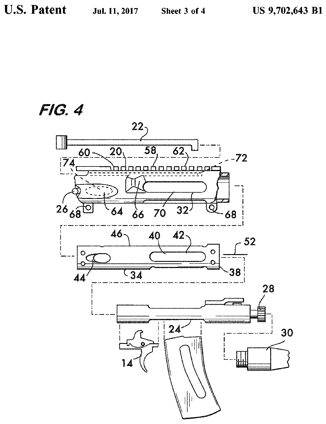
US Patent 9,702,643 — Bolt carrier bearing tube for rifle receiver
Matteo Viviano · assigned to Smith & Wesson Corp. · filed 2017-03-13 · granted 2017-07-11. Full patent (USPTO)
The upper receiver of the S&W AR-pattern rifle with a bearing tube for the bolt carrier, shown with the complete rifle, lower receiver and exploded upper.
Why this is the Smith & Wesson M&P15’s patent: listed on the maker’s patent-marking page — Virtual Patent Marking | Smith & Wesson — Smith & Wesson smith-wesson.com [6]: “9,702,643 M&P®10, M&P®15 sport”
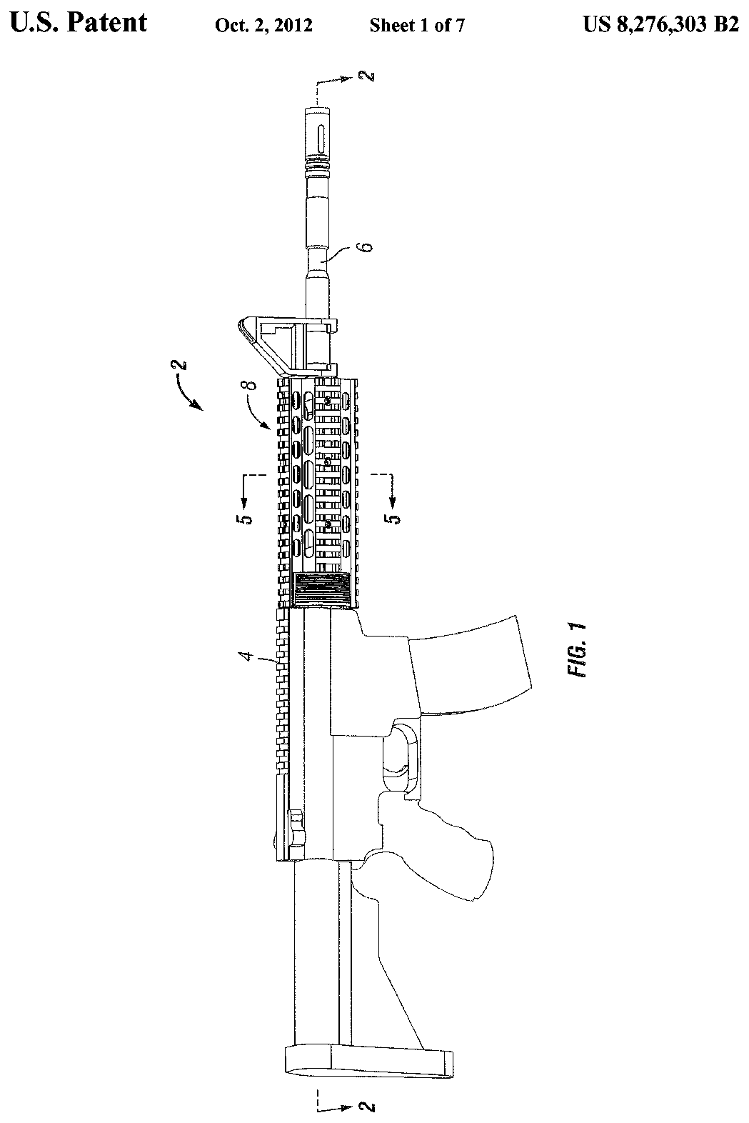
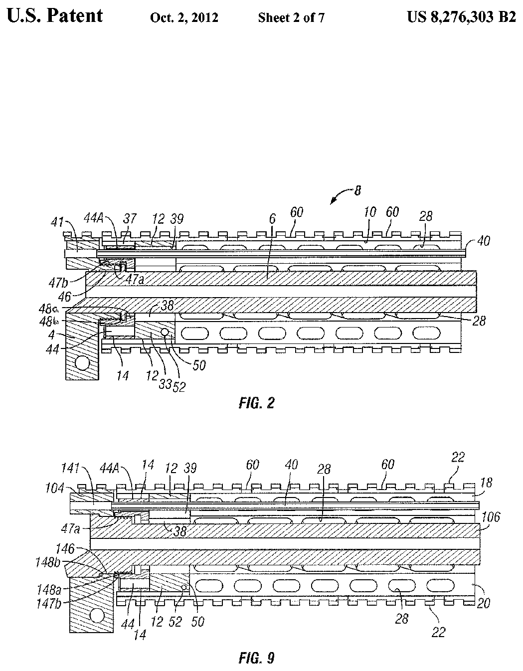
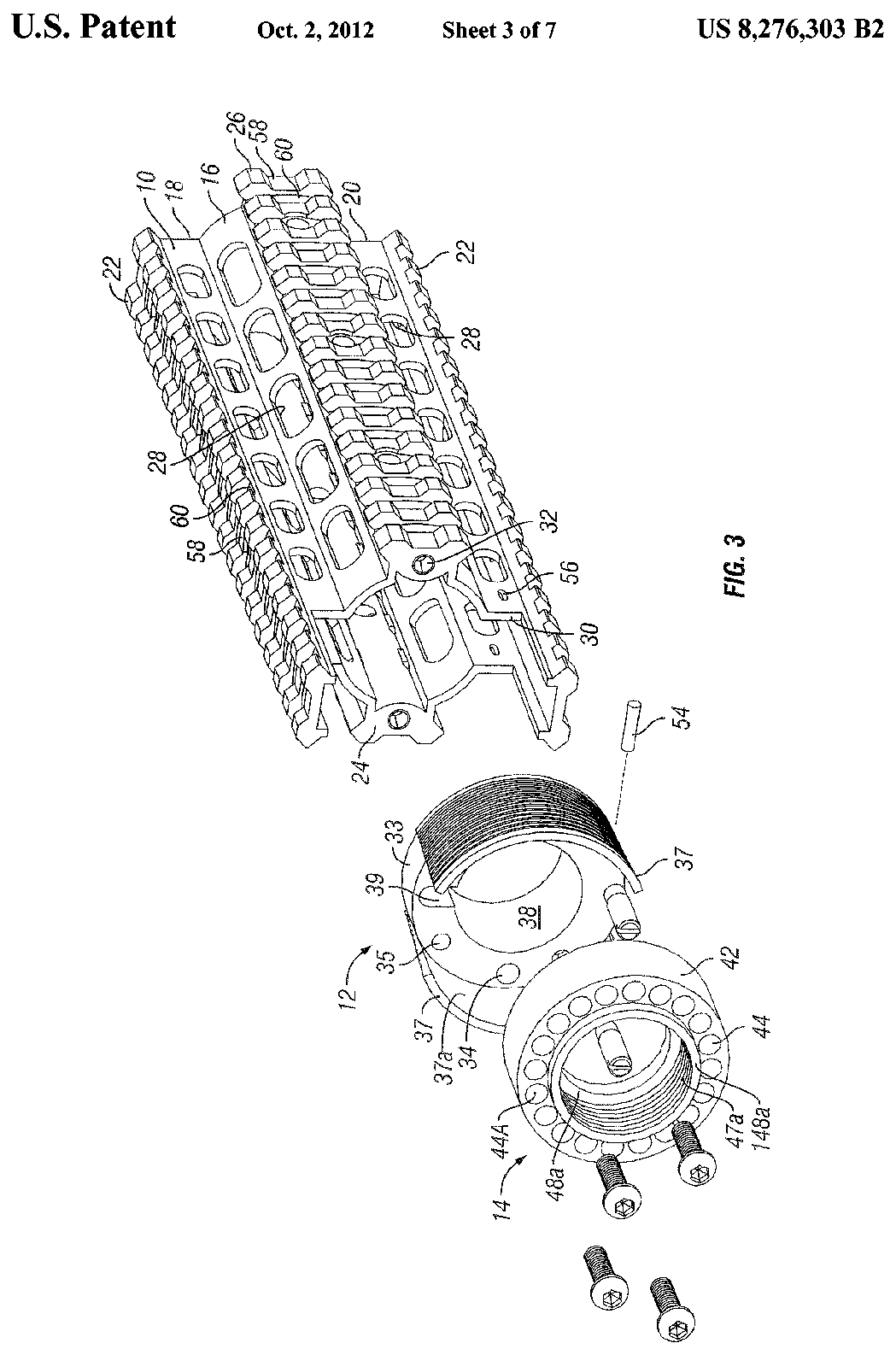
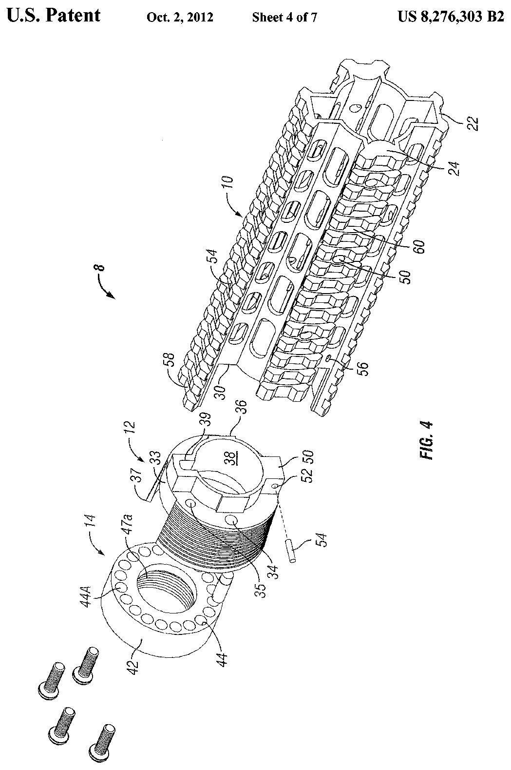
US Patent 8,276,303 — Firearm hand guard rail system
John Kapusta, Tai-Lai Ding · assigned to Smith & Wesson Corp. · filed 2010-04-28 · granted 2012-10-02. Full patent (USPTO)
The free-float hand guard rail system and its barrel-nut attachment to the upper receiver of an M&P15 rifle.
Why this is the Smith & Wesson M&P15’s patent: listed on the maker’s patent-marking page — Virtual Patent Marking | Smith & Wesson — Smith & Wesson smith-wesson.com [6]: “8,276,303 M&P®15 rifle only SKU 811041”
Torque specifications
| Fastener | Torque | Sequence, notes and the source's words | Where it comes from |
|---|---|---|---|
| One-piece free-floating forend/rail screws (3), 5/32˝ driver S&W M&P Sport series and Volunteer series centerfire rifles with a one-piece aluminum free-floating forend (e.g. M&P15 Sport III), if so-equipped |
45–50 in-lb 5.1–5.6 N·m · 3.7–4.2 ft-lb |
Check that these (3) forend screws are secure (FIGURE 68). “The forend/rail screws use a 5/32˝ driver and should be torqued to 45-50 inch-pounds.” |
Safety & Instruction Manual for Centerfire Semi-Automatic Rifles including Volunteer Series & Sport Series (p/n 3015611, REV S&W_M&P_CF_MSR_REV_022724, © 2024), linked from smith-wesson.com/products/mp-15-sport-iii — Smith & Wesson, p. 33 smith-wesson.canto.com [3] |
| Forend/rail screws (3), 5/32˝ driver S&W California Compliant Model centerfire semi-automatic rifle (M&P15 Sport III CA compliant) |
45–50 in-lb 5.1–5.6 N·m · 3.7–4.2 ft-lb |
Check that these (3) forend screws are secure (FIGURE 118). “The forend/rail screws use a 5/32˝ driver and should be torqued to 45-50 inch-pounds.” |
Safety & Instruction Manual for California Compliant Model Centerfire Semi-Automatic Rifle (© 2026), linked from smith-wesson.com/products/mp-15-sport-iii — Smith & Wesson, p. 48 smith-wesson.canto.com [4] |
| M-LOK accessory screws: polymer accessories to metal handguards S&W M&P15 / M&P Sport and Volunteer series rifles with M-LOK handguards (M-LOK accessory rails and accessories) |
15 in-lb 1.7 N·m · 1.2 ft-lb |
Thread the T-nuts onto the (nylon-patched) screws, insert and 'bias' the accessory toward the front of the slot, then 'tighten all fasteners to the recommended torque spec'; confirm the T-nut rotates 90° into the locked position. Source: 'The installation torque values are not minimums, they are recommended limits. The nylon patch compound (thread lock) may slightly affect the torque reading if using an in/lb torque wrench.' Threadlocker: Screws have a nylon patch; if worn, restore with Rocksett or Loctite blue thread-locker stick “For attaching polymer accessories to metal handguards: 15 in/lbs.” |
Safety & Instruction Manual for Centerfire Semi-Automatic Rifles including Volunteer Series & Sport Series (p/n 3015611, REV S&W_M&P_CF_MSR_REV_022724, © 2024), linked from smith-wesson.com/products/mp-15-sport-iii — Smith & Wesson, p. 57 smith-wesson.canto.com [3] |
| M-LOK accessory screws: polymer or metal accessories to polymer handguards S&W M&P15 / M&P Sport and Volunteer series rifles with M-LOK handguards (M-LOK accessory rails and accessories) |
15 in-lb 1.7 N·m · 1.2 ft-lb |
Thread the T-nuts onto the (nylon-patched) screws, insert and 'bias' the accessory toward the front of the slot, then 'tighten all fasteners to the recommended torque spec'; confirm the T-nut rotates 90° into the locked position. Source: 'The installation torque values are not minimums, they are recommended limits. The nylon patch compound (thread lock) may slightly affect the torque reading if using an in/lb torque wrench.' Threadlocker: Screws have a nylon patch; if worn, restore with Rocksett or Loctite blue thread-locker stick “For attaching polymer or metal accessories to polymer handguards: 15 in/lbs.” |
Safety & Instruction Manual for Centerfire Semi-Automatic Rifles including Volunteer Series & Sport Series (p/n 3015611, REV S&W_M&P_CF_MSR_REV_022724, © 2024), linked from smith-wesson.com/products/mp-15-sport-iii — Smith & Wesson, p. 57 smith-wesson.canto.com [3] |
| M-LOK accessory screws: metal accessories to metal handguards S&W M&P15 / M&P Sport and Volunteer series rifles with M-LOK handguards (M-LOK accessory rails and accessories) |
35 in-lb 4 N·m · 2.9 ft-lb |
Thread the T-nuts onto the (nylon-patched) screws, insert and 'bias' the accessory toward the front of the slot, then 'tighten all fasteners to the recommended torque spec'; confirm the T-nut rotates 90° into the locked position. Source: 'The installation torque values are not minimums, they are recommended limits. The nylon patch compound (thread lock) may slightly affect the torque reading if using an in/lb torque wrench.' Threadlocker: Screws have a nylon patch; if worn, restore with Rocksett or Loctite blue thread-locker stick “For attaching metal accessories to metal handguards: 35 in/lbs.” |
Safety & Instruction Manual for Centerfire Semi-Automatic Rifles including Volunteer Series & Sport Series (p/n 3015611, REV S&W_M&P_CF_MSR_REV_022724, © 2024), linked from smith-wesson.com/products/mp-15-sport-iii — Smith & Wesson, p. 57 smith-wesson.canto.com [3] |
Notes: S&W says of the M-LOK values that they "are not minimums, they are recommended limits" — treat them as the most to apply, not a target to reach. The forend/rail screw value applies only to rifles fitted with S&W's one-piece free-floating forend.
Materials and factory finish
As stated by Smith & Wesson. Prep, masking and cure depend on these; a polymer or aluminium part, a nitrided or anodised finish, and a blued steel part are each a different job. Variants with other finishes may exist — check the maker's page for the exact SKU on the bench.
| Component | Material | Factory finish | Where it comes from |
|---|---|---|---|
| Receiver (upper/lower) M&P15 Sport II, 16in, SKU 10202 | ALUMINUM | — | Smith & Wesson M&P15 Sport II — product specifications, SKU 10202 — Smith & Wesson Brands, Inc. smith-wesson.com [5] “FRAME MATERIAL … ALUMINUM” |
| Barrel M&P15 Sport II, 16in, SKU 10202 | 4140 CM | — | Smith & Wesson M&P15 Sport II — product specifications, SKU 10202 — Smith & Wesson Brands, Inc. smith-wesson.com [5] “BARREL MATERIAL … 4140 CM” |
| Whole firearm M&P15 Sport II, 16in, SKU 10202 | — | BLACK The maker states this for the firearm as a whole, not for a named part. | Smith & Wesson M&P15 Sport II — product specifications, SKU 10202 — Smith & Wesson Brands, Inc. smith-wesson.com [5] “COLOR/FINISH … BLACK” |
| Grips M&P15 Sport II, 16in, SKU 10202 | POLYMER | — | Smith & Wesson M&P15 Sport II — product specifications, SKU 10202 — Smith & Wesson Brands, Inc. smith-wesson.com [5] “GRIP … POLYMER” |
Parts
No parts list from Smith & Wesson is transcribed for this firearm.
Smith & Wesson's own documents label the parts on these pages — the links open each document at the page:
- Model and features identification (labelled photos of the rifle): Safety & Instruction Manual for Centerfire Semi-Automatic Rifles including Volunteer Series & Sport Series (p/n 3015611, REV S&W_M&P_CF_MSR_REV_022724, © 2024), linked from smith-wesson.com/products/mp-15-sport-iii — Smith & Wesson, p. 12–15 smith-wesson.canto.com [3]
Function check
- Verify the rifle is unloaded with no magazine inserted before each step.
- Charge the rifle to cock the hammer, place the selector on SAFE, and press the trigger. The hammer must not fall.
- Move the selector to SEMI and press the trigger. The hammer should fall.
- Hold the trigger to the rear, charge the rifle, then release the trigger slowly and listen for the disconnector to release the hammer to the trigger.
- Press the trigger again. The hammer should fall.
- Insert an empty magazine, charge the rifle, and confirm the bolt locks back.
Maintenance
Lubrication points
- Bolt locking lugs and body
- Cam pin and its track
- Outside of the carrier
- Gas rings
- Charging handle rails
Cleaning notes
A direct-impingement AR runs better wet than dry. Carbon on the bolt tail is normal and does not all need removing — focus on the locking lugs, gas rings, chamber, and bore. Do not scrape the bolt tail with steel.
Suggested inspection interval: roughly every 1000 rounds. This is a general guideline, not a manufacturer specification.
Wear parts to inspect
Gas rings · Extractor and its spring insert · Bolt (check the cam pin hole and lugs for cracks) · Buffer spring · Gas key staking
Common issues
| Symptom | Likely cause | What to do |
|---|---|---|
| Firing pin retaining pin will not install | Cam pin missing or not rotated | Install and rotate the cam pin. Never force the retaining pin. |
| Charging handle will not come out | Trying to remove it before the bolt carrier group | Remove the carrier first. |
| Failure to lock back on an empty magazine | Worn gas rings, gas leak, or a fouled gas key | Check gas rings first, then gas block alignment and gas key staking. see a gunsmith |
Similar manual of arms
Legal notes
Sourcing
- Confidence
- high — Cross-checked against a primary source such as the manufacturer's manual or an issuing military technical manual.
- Verification
- Checked against an armorer/technical manual
- Last updated
- 2026-10-29
References
Every source this page draws on, with its web address so you can read it yourself. Numbers in brackets elsewhere on the page point here.
- [1] TM 9-1005-319-10: Rifle, 5.56mm, M16A2/M4 Carbine — U.S. Department of the Army military technical manual primary source
- [2] Smith & Wesson M&P15 Owner’s Manual — Smith & Wesson manufacturer manual primary source
- [3] Safety & Instruction Manual for Centerfire Semi-Automatic Rifles including Volunteer Series & Sport Series (p/n 3015611, REV S&W_M&P_CF_MSR_REV_022724, © 2024), linked from smith-wesson.com/products/mp-15-sport-iii — Smith & Wesson manufacturer manual primary source
https://smith-wesson.canto.com/direct/document/s9hki7flkd0ar8802osm6p5j75/l-npJQUqV1KM75UlvNhw1q3siAA/original?content-type=application%2Fpdf (checked 2026-09-27) - [4] Safety & Instruction Manual for California Compliant Model Centerfire Semi-Automatic Rifle (© 2026), linked from smith-wesson.com/products/mp-15-sport-iii — Smith & Wesson manufacturer manual primary source
https://smith-wesson.canto.com/direct/document/3mde9sn0ct7ahcmuhjjkl7dt47/uQBnHdgJknuPT3BBklTqKtQQ6yM/original?content-type=application%2Fpdf (checked 2026-09-27) - [5] Smith & Wesson M&P15 Sport II — product specifications, SKU 10202 — Smith & Wesson Brands, Inc. website primary source
https://www.smith-wesson.com/product/m-p-15-sport-ii (checked 2026-10-03) - [6] Virtual Patent Marking | Smith & Wesson — Smith & Wesson website primary source
https://www.smith-wesson.com/company/virtual-patent-marking (checked 2026-10-13) - [7] DIY AR-15 Build: Pivot Pin Installation — ITS Tactical website secondary source
https://www.itstactical.com/?p=10638 (checked 2026-10-29) - [8] (Gunsmithing the AR-15 #2) The 30-Second AR Check — Gun Tests website secondary source
https://www.gun-tests.com/?p=26007 (checked 2026-10-29) - [9] The Gun Digest Book of Exploded Gun Drawings (975 isometric views) — Colt 'AR15-A2 Sporter Autoloading Rifle' — Gun Digest Books / Krause Publications (scan on archive.org) website secondary source
https://archive.org/download/the-book-of-exploded-gun-drawings-975-isometric-views/The%20Book%20of%20Exploded%20Gun%20Drawings%20-%20975%20Isometric%20Views.pdf (checked 2026-10-29)
Notes: Illustrated on 2026-09-14 with M16 figures from TM 9-1005-249-23&P (public domain, US Government work). Same pattern, same parts arrangement. Field strip and bolt carrier group disassembly follow the standard AR-15 pattern. Sport models omit the forward assist and dust cover on some configurations; that changes nothing about the field strip.