← All firearms · Printable work order
Springfield M1903
- moderate
- Shop tier 2
- medium confidence
- Rifle
- surplus
- milsurp
- corrosive ammo
- historic
- controlled round feed
- stripper clip
- service rifle
- magazine cutoff
field strip ~3 min · reassembly ~4 min · detail strip ~35 min
Specifications
- Manufacturer
- Springfield Armory (U.S. Government Arsenal)
- Origin
- United States
- Category
- Rifle
- Action
- Bolt action
- Calibers
- .30-06 Springfield
- Capacity
- 5 rounds in the internal magazine, stripper-clip loaded
- Production
- 1903–1945 (surplus)
- Also known as
- M1903A3, Springfield ’03, .30-06 Springfield rifle
Model-specific safety
- These rifles are decades old and most have been arsenal rebuilt with mixed parts. Have headspace checked by a gunsmith before firing any rifle of unknown history.
- Surplus ammunition of this era is frequently corrosively primed. Clean with a water-based solvent the same day you shoot.
- Newly imported rifles are often packed in cosmoline throughout, including the bolt and firing pin channel. Clean it out before firing — a firing pin held forward by congealed grease causes slam fires.
- The 1903 is a Mauser-derived controlled-round-feed action. Do not single-load by dropping rounds into the chamber — feed from the magazine so the extractor picks up the rim.
- The magazine cut-off lever on the left side of the receiver has three positions, and the MIDDLE position is what releases the bolt. With the cut-off up (ON) the rifle feeds from the magazine; down (OFF) it functions as a single loader. This three-position cut-off is the detail people miss when a bolt will not come out.
- Low-numbered 1903 receivers — broadly those below serial 800,000 from Springfield Armory and below 285,507 from Rock Island — were single heat-treated and have a documented history of receiver failures. Do not fire a low-numbered 1903 without having it evaluated by a knowledgeable gunsmith. This is the most important safety point about this rifle.
Under spring tension
- Mainspring inside the bolt
- Magazine follower spring
Easily lost parts
Bolt components · Firing pin · Extractor · Floorplate components
Tools
| Tool | Required | Used for | Substitute |
|---|---|---|---|
| Bore guide | Yes | Cleaning from the breech without wearing the throat or the crown. On a surplus rifle the crown is often the difference between accuracy and none. |
Shop difficulty
Shop tier 2 Tier 2 — moderate among rifles and carbines, for the full job: strip to the parts that get coated and put it back together working. A bolt action, but with more small sprung parts than a modern sporter. To strip to coatable parts, the bolt sleeve lock spring is compressed while a pin is driven, the safety needs its assembling tool, the cut-off spring and plunger fly, and the sear spring is held while its pin goes in. There are several traps but no timing.
Parts: 93 pieces (complete U.S. Rifle cal. .30 Model of 1903 (rod-less 1905/06 pattern, straight-grip stock, original leaf rear sight, magazine cut-off) per the Ordnance Dept. list 'Component parts of rifle (Ninety-thr), from Description and Rules for the Management of the United States Rifle, Caliber .30, Model of 1903 (Ordnance Dept. No. 1923; March 3, 1904, revised March 20, 1914) — War Department, Office of the Chief of Ordnance (Government Printing Office, 1914); scan at archive.org item 'descriptionrules00unit', pp. 5-6 ('Component parts of rifle') archive.org [5].
Bench time: about 50 min to strip, 75 min to rebuild (estimate). Stock group (bands, guard, butt plate), bolt detail strip, floor plate group, cut-off, sear, ejector, sights per TM 9-1270. Barrel stays in receiver.
Small parts: 15 pins, 12 springs, 2 detents or plungers (counted by name in the same list (line items = pieces for all of these). Pins: base pin, stud pin, bolt stop pin, butt plate pin, butt swivel pin, ejector pin, floor plate pin, front sight pin, drift )
What comes off for coating
- Stock group: upper and lower bands, hand guard, guard screws and trigger guard, floor plate group, butt plate
- Bolt: bolt sleeve and lock, safety lock, striker, firing pin sleeve, mainspring, extractor and collar
- Receiver: cut-off, spring and plunger, sear, trigger, sear spring, ejector and pin, bolt stop (if fitted), rear sight group
- Barrel: front sight and stud (only if necessary), rear sight fixed base (only if necessary)
Special tools
- safety lock assembling tool (or small screwdriver) — Safety lock plunger
- brass drift / hard wood block — Sight bases
- vise with wood block — Rear sight base spring
Known pain points
- The cut-off's spring and plunger fly out as the cut-off is refitted, unless it is held firmly while the spindle goes in. (reassembly)
Source: TM 9-1270 Ordnance Maintenance: U.S. Rifles, Cal. .30, M1903, M1903A1, M1903A3 and M1903A4 — War Department archive.org [4] — “Hold cut-off firmly in position while inserting the spindle, as spring and plunger may fly out when spring is compressed.” - The safety lock goes back into the bolt sleeve with a dedicated safety-lock assembling tool (or a small screwdriver) forcing its plunger. (reassembly)
Source: TM 9-1270 Ordnance Maintenance: U.S. Rifles, Cal. .30, M1903, M1903A1, M1903A3 and M1903A4 — War Department archive.org [4] — “introduce the point of the safety lock assembling tool provided for this purpose, or a small screwdriver, if the special tool is not available, between the safety-lock spindle and safety-lock plunger” - The bolt sleeve lock and its spring must be held compressed while the pin is driven. The sear spring must be held compressed while the sear pin goes in. (reassembly)
Source: TM 9-1270 Ordnance Maintenance: U.S. Rifles, Cal. .30, M1903, M1903A1, M1903A3 and M1903A4 — War Department archive.org [4] — “In assembling the bolt sleeve lock to the bolt sleeve, be careful to compress the lock and spring while driving in the pin from the bottom of the bolt sleeve.” - Partly relieving the mainspring when the striker comes out pinches fingers. (disassembly)
Source: TM 9-1270 Ordnance Maintenance: U.S. Rifles, Cal. .30, M1903, M1903A1, M1903A3 and M1903A4 — War Department archive.org [4] — “Care should be exercised in this operation to avoid pinching the fingers when the spring pressure is released.” - Some A3/A4 screws and pins are expanded or upset at the factory and must not be fully removed (stacking swivel screw, lower band screw, butt plate trap pin). The barrel must not be unscrewed. (disassembly)
Source: TM 9-1270 Ordnance Maintenance: U.S. Rifles, Cal. .30, M1903, M1903A1, M1903A3 and M1903A4 — War Department archive.org [4] — “They should never be unscrewed except at an ordnance establishment properly equipped for this work.”
Fit or check on rebuild
- Cut-off screw engages spindle — Otherwise the cut-off works loose.
Source: TM 9-1270 Ordnance Maintenance: U.S. Rifles, Cal. .30, M1903, M1903A1, M1903A3 and M1903A4 — War Department archive.org [4] — “making sure that it is screwed in far enough to engage the spindle.” - Headspace if the bolt is swapped — Military bolts are not always matched to the rifle. Well-known check.
- Re-zero sights or scope — Sights and optics come off for coating, and point of impact must be re-confirmed. This is a standard check, so no source.
This is Pew-Takedown's rating, not the manufacturer's. How tiers are rated. Forum reports are owners' experience, not specifications.
Procedures
Clear and Make Safe
Clear & Make Safe- Point the muzzle in a safe direction and keep your finger off the trigger.
- Rotate the safety at the rear of the bolt to the safe position.
- Lift the bolt handle and draw the bolt fully rearward, extracting and ejecting any chambered round.
- Press the floorplate release and let the floorplate drop to release rounds from the magazine, or cycle the bolt repeatedly to feed and eject each round.Removed at this step:
Rounds in the magazine - Inspect the chamber and magazine well with a light and physically confirm the chamber is empty.
- Close the floorplate and remove all live ammunition from the work area.
Field Strip — Bolt Removal
Field StripBolt removal is the whole of routine maintenance. The bore cleans from the breech with the bolt out.
- Complete the Clear and Make Safe procedure.
- Move the safety to the vertical position and set the magazine cut-off lever on the left side of the receiver to its middle position.WarningThe bolt will not release unless the cut-off is in the middle position. Do not force it.
- Lift the bolt handle and draw the bolt fully rearward.
- Withdraw the bolt rearward out of the receiver.Removed at this step:
Bolt assembly - Clean the bore from the breech using a bore guide, and clean the bolt face, lugs, and chamber.WarningAlways use a bore guide on a surplus rifle. Cleaning rod wear at the crown is a permanent accuracy loss and is very common on milsurp.
- Stop here for routine maintenance. Bolt disassembly is a separate procedure and is not part of normal cleaning.
Disassemble the bolt
Detail Strip tools required gunsmith recommendedTakes the removed bolt apart: bolt sleeve and firing pin mechanism, striker, mainspring, extractor, safety lock and bolt sleeve lock (TM 9-1270 para 9). The extractor collar, the safety lock assembly and the firing pin rod with cocking piece are permanent assemblies and are not taken apart. TM 9-1270 is written for ordnance maintenance personnel (para 1a) and says removing the groups (para 7) is sufficient for field cleaning, with the detailed disassembly of section II reserved for trained ordnance personnel (para 59b).
Follows TM 9-1270 Ordnance Maintenance: U.S. Rifles, Cal. .30, M1903, M1903A1, M1903A3 and M1903A4 — War Department, para 9, pp. 42-45 archive.org [4]
- Hold the bolt in the left hand with the firing pin cocked and the safety lock in the SAFE position.
- Press the bolt sleeve lock in with the right thumb to unlock the bolt sleeve from the bolt.
- Unscrew the bolt sleeve by turning it to the left.Removed at this step:
Bolt sleeve with firing pin mechanism - Hold the bolt sleeve between the forefinger and thumb of the left hand and draw the cocking piece back with the middle finger and thumb of the right hand.
- Turn the safety lock down to the READY position with the right forefinger, letting the cocking piece move forward in the bolt sleeve to partially relieve the mainspring.WarningTake care to avoid pinching the fingers when the spring pressure is released.
- With the cocking piece against the breast, draw back the firing pin sleeve with the forefinger and thumb of the right hand and hold it there.
- Remove the striker with the left hand.WarningPoint the striker away from all personnel and relieve the mainspring pressure gradually to avoid losing parts.Removed at this step:
Striker - Remove the firing pin sleeve and mainspring.Removed at this step:
Firing pin sleeveMainspring - Pull the firing pin out of the bolt sleeve.Removed at this step:
Firing pin assembly - Turn the extractor to the right, forcing its tongue out of its groove in the front of the bolt.
- Force the extractor forward and off the bolt.TipThe extractor collar is bent onto the bolt in manufacture and stays on it.Removed at this step:
Extractor - Turn the safety lock to the dismounting bevel position on the bolt sleeve, halfway between READY and the vertical position.
- Remove the safety lock by striking the front face of the thumb piece a light blow.Removed at this step:
Safety lock - Drive out the bolt sleeve lock pin from the top.Removed at this step:
Bolt sleeve lock pin - Remove the bolt sleeve lock and spring.WarningBe careful not to lose the spring.Removed at this step:
Bolt sleeve lockBolt sleeve lock spring
Remove and disassemble the floor plate, magazine spring and follower
Detail Strip tools required gunsmith recommendedReleases the floor plate group from the trigger guard (para 7c) and separates the magazine spring from the floor plate and follower (para 11). Rifles M1903A3 and M1903A4 have no floor plate; their spring is separated from the follower in the same way. TM 9-1270 is written for ordnance maintenance personnel (para 1a) and says removing the groups (para 7) is sufficient for field cleaning, with the detailed disassembly of section II reserved for trained ordnance personnel (para 59b).
Applies to: M1903 and M1903A1
Follows TM 9-1270 Ordnance Maintenance: U.S. Rifles, Cal. .30, M1903, M1903A1, M1903A3 and M1903A4 — War Department, paras 7c and 11, pp. 38 and 47 archive.org [4]
- With the bullet end of a cartridge or a pin drift, press on the floor plate catch through the hole in the floor plate while drawing the bullet to the rear to release the floor plate.
- Remove the floor plate, magazine spring and follower together.Removed at this step:
Floor plateMagazine springFollower - Raise the rear end of the lower portion of the magazine spring high enough to clear the lug on the floor plate and draw the spring out of its mortise.
- Remove the follower from the spring in the same manner.
Remove the M1903A3-type follower through the receiver
Detail StripRemoves the M1903A3-type follower and magazine spring from an M1903A3 through the top of the receiver without removing the trigger guard magazine assembly (TM 9-1270 para 7d(2)). Part of the removal of groups for ordinary cleaning, not detailed disassembly. Not practical on the M1903A4 because of the scope mount base.
Applies to: M1903A3 fitted with the M1903A3-type follower
Follows TM 9-1270 Ordnance Maintenance: U.S. Rifles, Cal. .30, M1903, M1903A1, M1903A3 and M1903A4 — War Department, para 7d(2), p. 40 archive.org [4]
- Position the rifle with the muzzle to the left.WarningNever use this method when an M1903-type follower is fitted; it will damage the follower and the chamber of the barrel.
- Set the cut-off at the ON position.
- Unlock the bolt and pull it to its extreme rearward position.
- Insert the nose of a bullet directly in front of the ejector and against the left side of the follower rib.
- Tip the rear of the follower downward and toward the right side of the receiver until the front left side of the follower emerges through the magazine slot at the front of the receiver and rests on the lip of the receiver.
- Move the bolt forward slowly against the rear face of the follower to disengage the follower from the magazine spring.WarningDo not allow the front end of the follower to strike the mouth of the chamber.TipIt may be necessary to pry up the rear end of the follower to engage the bolt.
- Pull the bolt to the rear and remove the follower and magazine spring.Removed at this step:
FollowerMagazine spring
Remove the bands, hand guard and trigger guard, and strip the stock
Detail Strip tools required gunsmith recommendedWith the bolt and floor plate group removed, takes off the upper and lower bands, hand guard and trigger guard, lifts the barrel and receiver out of the stock, and strips the stock fittings (TM 9-1270 para 13). Written for the M1903 and M1903A1, with the manual's M1903A3/A4 differences in the tips. TM 9-1270 is written for ordnance maintenance personnel (para 1a) and says removing the groups (para 7) is sufficient for field cleaning, with the detailed disassembly of section II reserved for trained ordnance personnel (para 59b).
Follows TM 9-1270 Ordnance Maintenance: U.S. Rifles, Cal. .30, M1903, M1903A1, M1903A3 and M1903A4 — War Department, para 13, pp. 48-55 archive.org [4]
- Remove the upper band screw.TipM1903A3/A4: the bayonet stud band is removed the same way by removing the bayonet stud band screw.Removed at this step:
Upper band screw - Drive the upper band forward with a few short blows on its lug with a hard wood block.TipThe upper band can only come off the barrel after the front sight movable stud is removed (M1903A3: after the front sight group is removed).
- Unscrew the stacking swivel screw and remove the stacking swivel.WarningM1903A3/A4: the end of the stacking swivel screw is expanded; loosen it to free the stacking swivel band but do not remove it from the band, or the threads will be stripped.Removed at this step:
Stacking swivel - Unscrew the lower band screw and remove the lower band swivel.WarningM1903A3/A4: the end of the lower band screw is expanded and should not be removed; back it out about 1/8 inch and spread the prongs of the band instead.Removed at this step:
Lower band swivel - Press in the rear end of the lower band spring and move the lower band forward beyond the end of the stock.Removed at this step:
Lower band - Draw the hand guard assembly forward until it is free of the fixed base and remove it.WarningDo not remove the hand guard clips unless necessary, as they may become bent out of shape.TipM1903A3/A4: the barrel guard is drawn free of the barrel guard ring the same way.Removed at this step:
Hand guard assembly - Remove the front and rear guard screws and the trigger guard group.TipIt may be necessary to tap gently on the front and rear of the trigger guard to loosen it.Removed at this step:
Guard screwsTrigger guard group - To remove the floor plate catch and spring from the trigger guard, drive out the floor plate catch pin from either side.TipThe M1903A3/A4 trigger guard magazine assembly has no floor plate catch.Removed at this step:
Floor plate catch pinFloor plate catchFloor plate catch spring - Remove the barrel and receiver assembly group from the stock.WarningThe barrel is threaded into the receiver at manufacture and should never be unscrewed except at an ordnance establishment properly equipped for this work.Removed at this step:
Barrel and receiver assembly - Drive the lower band spring spindle out of its hole in the stock from the left.Removed at this step:
Lower band spring - Punch out the guard screw bushing from the top or bottom.Removed at this step:
Guard screw bushing - Unscrew the butt swivel screws and remove the butt swivel assembly.Removed at this step:
Butt swivel assembly - Unscrew the butt plate screws and remove the butt plate assembly.Removed at this step:
Butt plate assembly - Unscrew the butt plate spring screw and remove the butt plate spring.TipM1903 and M1903A1 only.Removed at this step:
Butt plate spring - Drive out the butt plate pin and remove the butt plate cap.WarningM1903A3/A4: the butt plate trap pin is upset at its ends at manufacture and should not be removed.Removed at this step:
Butt plate pinButt plate cap
Remove the front sight, movable stud and fixed stud
Detail Strip tools required gunsmith recommendedRemoves the front sight blade and movable stud, and if necessary the fixed stud, from the barrel (TM 9-1270 para 15a-b). Barrel work; TM 9-1270 is written for ordnance maintenance personnel (para 1a) and says removing the groups (para 7) is sufficient for field cleaning, with the detailed disassembly of section II reserved for trained ordnance personnel (para 59b).
Follows TM 9-1270 Ordnance Maintenance: U.S. Rifles, Cal. .30, M1903, M1903A1, M1903A3 and M1903A4 — War Department, para 15a-b, pp. 55 and 57 archive.org [4]
- Drive out the front sight pin from the left and remove the front sight.Removed at this step:
Front sight pinFront sight - Unscrew the front sight screw and remove the movable stud by tapping it out sideways.TipM1903 and M1903A1.Removed at this step:
Front sight screwMovable stud - Only if necessary, drive out the fixed stud pin.WarningThe fixed stud should never be removed from the barrel unless necessary.Removed at this step:
Fixed stud pin - Drive the fixed stud forward off the barrel by striking it with a hard wood block.TipM1903A3: the front sight base corresponds to the fixed stud and is keyed to the barrel; remove the base pin, drive the base forward, then lift the key from its slot.Removed at this step:
Fixed stud
Disassemble the barrel-mounted rear sight
Detail Strip tools required gunsmith recommendedRemoves the movable base, leaf, slide, drift slide and windage screw of the barrel-mounted ladder rear sight, and if necessary the fixed base (TM 9-1270 para 15c-d). TM 9-1270 is written for ordnance maintenance personnel (para 1a) and says removing the groups (para 7) is sufficient for field cleaning, with the detailed disassembly of section II reserved for trained ordnance personnel (para 59b).
Applies to: M1903 and M1903A1
Follows TM 9-1270 Ordnance Maintenance: U.S. Rifles, Cal. .30, M1903, M1903A1, M1903A3 and M1903A4 — War Department, para 15c-d, p. 60 archive.org [4]
- Turn the windage screw until the movable base has revolved far enough that its worm gear is clear of the windage screw threads and its front and rear lips are free of the undercuts on the fixed base.
- Lift the movable base off the pivot lug on the fixed base.Removed at this step:
Movable base - Turn the rear sight leaf to the forward horizontal position.
- Place the movable base in a vise with a small block of wood bearing on the rear sight base spring as near the joint of the sight leaf as possible.WarningMake sure no pressure of the vise is exerted on the ears or shoulder of the movable base.
- Tighten the vise gently so the block of wood relieves the spring pressure on the rear sight leaf and joint pin.
- Push or drive out the joint pin with a small pin drift and remove the rear sight leaf.Removed at this step:
Joint pinRear sight leaf - Take the movable base out of the vise and drive the sight base spring forward out of its mortise with a pin drift inserted in the hole in the spring.Removed at this step:
Sight base spring - Unscrew the rear sight slide cap screw from the slide cap.Removed at this step:
Slide cap screw - Drive out the rear sight slide cap pin.Removed at this step:
Slide cap pin - Unscrew and take out the rear sight slide binding screw.Removed at this step:
Slide binding screw - Drive the rear sight slide cap very gently to the left out of its mortise in the rear sight slide.
- Remove the slide and cap from the sight leaf.Removed at this step:
Rear sight slideSlide cap - Slide the drift slide to the top of the leaf and out of its groove.WarningThe drift slide pin is riveted in place at manufacture and is not to be removed.Removed at this step:
Drift slide - Compress the windage screw spring by forcing the screw collar toward the windage screw knob.
- Tap alternately on the taper head and the screw knob toward the breech until the windage screw assembly comes out of its seat.TipThe windage screw, knob and pin are a permanent assembly.Removed at this step:
Windage screw assembly - Only if necessary, drive out the fixed base pin.WarningThe fixed base should never be removed from the barrel unless necessary.Removed at this step:
Fixed base pin - Drive the fixed base forward with a hard wood block and remove the spline.WarningTake care not to damage the overhanging lugs.Removed at this step:
Fixed baseSpline
Disassemble the receiver group
Detail Strip tools required gunsmith recommendedWith the barrel and receiver out of the stock, removes the magazine cut-off, ejector, sear, sear spring, trigger and bolt stop from the receiver (TM 9-1270 para 17a-e). Touches the sear; TM 9-1270 is written for ordnance maintenance personnel (para 1a) and says removing the groups (para 7) is sufficient for field cleaning, with the detailed disassembly of section II reserved for trained ordnance personnel (para 59b).
Follows TM 9-1270 Ordnance Maintenance: U.S. Rifles, Cal. .30, M1903, M1903A1, M1903A3 and M1903A4 — War Department, para 17a-e, p. 62 archive.org [4]
- Loosen the cut-off screw in the end of the thumb piece until it disengages the groove in the cut-off spindle.
- Insert the blade of a screwdriver in the notch in the rear of the spindle and force the spindle out.Removed at this step:
Cut-off spindle - Remove the cut-off, its spring and plunger, and the cut-off screw.WarningBe careful not to lose the spring and plunger.Removed at this step:
Cut-offCut-off springCut-off plungerCut-off screw - Drive out the ejector pin from the upper side and remove the ejector.Removed at this step:
Ejector pinEjector - Drive out the sear pin from the right and remove the sear, sear spring and trigger.Removed at this step:
Sear pinSearSear springTrigger - Drive out the trigger pin from either side to separate the trigger from the sear.Removed at this step:
Trigger pin - Insert a small punch in the hole in the end of the bolt stop spring and draw it from its pocket until the pin is free, then pull out the bolt stop assembly.TipSome M1903 and M1903A1 rifles have no bolt stop assembly; the pin and spring are a permanent assembly.Removed at this step:
Bolt stop assembly
Disassemble the receiver-mounted rear sight
Detail Strip tools required gunsmith recommendedRemoves the windage index knob, windage yoke screw, windage yoke and aperture group, and if necessary the sight base from the M1903A3 receiver bridge (TM 9-1270 para 17f). TM 9-1270 is written for ordnance maintenance personnel (para 1a) and says removing the groups (para 7) is sufficient for field cleaning, with the detailed disassembly of section II reserved for trained ordnance personnel (para 59b).
Applies to: M1903A3
Follows TM 9-1270 Ordnance Maintenance: U.S. Rifles, Cal. .30, M1903, M1903A1, M1903A3 and M1903A4 — War Department, para 17f, pp. 62 and 65 archive.org [4]
- Turn out the windage index knob screw in the knurled edge of the knob far enough to free the knob from the windage yoke screw, and pull the knob off the yoke screw.TipTighten the windage index knob screw back into the knob to prevent its loss.Removed at this step:
Windage index knob - Turn the windage yoke screw out of the sight base while holding the remaining parts from springing out.Removed at this step:
Windage yoke screw - Lift the windage yoke and aperture group out of the base.WarningDo not lose the windage yoke plunger and spring in the bottom of the yoke or the index knob spring in the right side of the sight base.Removed at this step:
Windage yoke and aperture groupWindage yoke plungerWindage yoke plunger springIndex knob spring - Loosen the aperture slide screw and pull the slide aperture, with screw and slide aperture spring attached, forward out of the windage yoke.Removed at this step:
Slide aperture - Only if necessary, turn out the base screw in the top of the sight base and drive the base from the receiver with a brass drift or hard wood block.WarningThe sight base should not be removed unless necessary.TipSights of recent manufacture have no base screw; the base is staked in place.Removed at this step:
Sight baseBase screw
Reassemble the bolt
Detail Reassembly tools required gunsmith recommendedReassembles bolt sleeve lock, safety lock, extractor and firing pin mechanism and screws the bolt sleeve home (TM 9-1270 para 10). TM 9-1270 is written for ordnance maintenance personnel (para 1a) and says removing the groups (para 7) is sufficient for field cleaning, with the detailed disassembly of section II reserved for trained ordnance personnel (para 59b).
Follows TM 9-1270 Ordnance Maintenance: U.S. Rifles, Cal. .30, M1903, M1903A1, M1903A3 and M1903A4 — War Department, para 10, pp. 45-47 archive.org [4]
- Compress the bolt sleeve lock and spring in the bolt sleeve while driving in the lock pin from the bottom of the bolt sleeve.
- Insert the safety lock spindle in its hole in the bolt sleeve as far as it will go.
- With the thumb piece vertical and pressed against a rigid object, introduce the point of the safety lock assembling tool, or a small screwdriver, between the spindle and the safety lock plunger, forcing the plunger into the thumb piece until it slips over the edge of the sleeve.
- Press further on the safety lock thumb piece while gradually withdrawing the tool to complete the assembly.
- Grasp the rear of the bolt in the left hand, handle up, and turn the extractor collar with the right thumb and forefinger until its lug is in line with the safety lug on the bolt.
- Insert the lug on the collar in the undercuts in the extractor by pushing the extractor to the rear until its tongue contacts the rim on the face of the bolt.TipSlight pressure with the left thumb on top of the rear part of the extractor helps.
- Turn the extractor to the right until it is over the right lug.
- Take the bolt in the right hand and press the hook of the extractor against the butt plate or some rigid object until the tongue on the extractor enters its groove in the bolt.
- With the safety lock turned down to READY so the firing pin can enter the bolt sleeve as far as possible, assemble the bolt sleeve and firing pin.
- Place the cocking piece against the breast and put on the mainspring, firing pin sleeve and striker.
- Hold the cocking piece between the thumb and forefinger of the left hand and press the striker point against something not hard enough to injure it, forcing the cocking piece back until the safety lock can be turned to the vertical position with the right hand.
- Insert the firing pin in the bolt and screw up the bolt sleeve, turning it to the right, until the bolt sleeve lock enters its notch on the bolt.
Reassemble and install the floor plate, magazine spring and follower
Detail Reassembly gunsmith recommendedReassembles the magazine spring to the floor plate and follower (para 12a) and reinstalls the group in the rifle (para 8a). TM 9-1270 is written for ordnance maintenance personnel (para 1a) and says removing the groups (para 7) is sufficient for field cleaning, with the detailed disassembly of section II reserved for trained ordnance personnel (para 59b).
Applies to: M1903 and M1903A1
Follows TM 9-1270 Ordnance Maintenance: U.S. Rifles, Cal. .30, M1903, M1903A1, M1903A3 and M1903A4 — War Department, paras 12a and 8a, pp. 47-48 and 40 archive.org [4]
- Insert the larger end of the magazine spring in the mortise of the floor plate and push it in as far as possible, with the rear end of the lower portion ahead of the lug on the rear end of the floor plate.
- Insert the other end of the spring in the mortise of the follower in the same way.
- Insert the group into the magazine, follower first, with the narrow end of the follower forward.
- Place the tenon on the front end of the floor plate in its recess in the magazine, then the lug on the rear end of the floor plate in its slot in the trigger guard.
- Press the rear end of the floor plate forward and inward at the same time, forcing it into its seat in the trigger guard.
Reinstall the M1903A3-type follower through the receiver
Detail ReassemblyReinstalls the magazine spring and M1903A3-type follower in an M1903A3 with the trigger guard magazine assembly still in place (TM 9-1270 para 8b(2)).
Applies to: M1903A3 fitted with the M1903A3-type follower
Follows TM 9-1270 Ordnance Maintenance: U.S. Rifles, Cal. .30, M1903, M1903A1, M1903A3 and M1903A4 — War Department, para 8b(2), p. 41 archive.org [4]
- Position the rifle with the muzzle to the left.
- Insert the small end of the magazine spring under the ears of the follower and slide it fully forward.
- Compress the magazine spring against the follower and insert the spring and follower sideways into the magazine opening of the receiver, small end of the follower toward the front and spring toward the left (near) side of the receiver.
- Rotate the follower so that its rib projects upward.
- Press the rear end of the follower down to the bottom of the magazine to make sure the spring is seated under the ears of the follower.
Reassemble the stock and install the barrel and receiver, trigger guard, hand guard and bands
Detail Reassembly tools required gunsmith recommendedRefits the stock fittings, sets the barrel and receiver in the stock and installs the trigger guard, hand guard and bands (TM 9-1270 para 14). TM 9-1270 is written for ordnance maintenance personnel (para 1a) and says removing the groups (para 7) is sufficient for field cleaning, with the detailed disassembly of section II reserved for trained ordnance personnel (para 59b).
Follows TM 9-1270 Ordnance Maintenance: U.S. Rifles, Cal. .30, M1903, M1903A1, M1903A3 and M1903A4 — War Department, para 14, p. 55 archive.org [4]
- Assemble the butt plate cap and pin to the butt plate.
- Place the butt plate spring on the shank of the cap, curved side down, and thread in the butt plate spring screw.TipM1903 and M1903A1 only.
- Place the butt plate assembly on the butt of the stock and thread in the butt plate screws, the short screw passing through the top tang of the butt plate.
- Place the butt swivel assembly in its seat in the under side of the stock butt and thread in its screws.
- Insert the guard screw bushing in its seat in the under side of the stock to the rear of the magazine opening and drive it home.
- Insert the spindle of the lower band spring in the hole in the right side of the stock and drive it in with a wood block so that the spring seats in its groove in the stock.
- Reinstall the barrel and receiver assembly group in the stock.
- Assemble the floor plate catch spring and catch to the trigger guard and drive in the catch pin.TipThere is no floor plate catch group in the M1903A3/A4 trigger guard magazine assembly.
- Insert the trigger guard in the stock and thread in the front (short) and rear (long) guard screws.
- Place the hand guard assembly on top of the barrel.
- Slide the upper and lower bands into place to bind the stock and hand guard together, with the letter U on the lower band facing the muzzle.TipM1903A3/A4: assemble the stacking swivel band to the stock and barrel guard before the bayonet stud band; a removed barrel guard ring goes on the barrel first.
- Reassemble the lower band swivel to the lower band and the stacking swivel to the upper band.
- Thread in the upper band screw from the right side.
Install the fixed stud, movable stud and front sight
Detail Reassembly tools required gunsmith recommendedReinstalls the fixed stud (or M1903A3 front sight base and key), movable stud and front sight (TM 9-1270 para 16b-d). The bands must already be on the barrel. TM 9-1270 is written for ordnance maintenance personnel (para 1a) and says removing the groups (para 7) is sufficient for field cleaning, with the detailed disassembly of section II reserved for trained ordnance personnel (para 59b).
Follows TM 9-1270 Ordnance Maintenance: U.S. Rifles, Cal. .30, M1903, M1903A1, M1903A3 and M1903A4 — War Department, para 16b-d, pp. 61-62 archive.org [4]
- Place the front band (M1903A3: stacking swivel band, bayonet stud band and barrel guard less ring) on the barrel before assembling the front sight group.
- If the fixed stud was removed, drive it onto the barrel over the spline until the fixed stud pin can be inserted, and make sure the pin and stud are secure.WarningM1903A3: seat the front sight base key, pin groove up, in its groove in the muzzle end of the barrel before driving the base on; the key must not move, and if loose it is peened in place.
- Assemble the movable stud to the fixed stud and thread in the front sight screw.
- Assemble the front sight with its curved edge forward and drive in the front sight pin securely.
Reassemble the barrel-mounted rear sight
Detail Reassembly tools required gunsmith recommendedReinstalls the fixed base if removed, then the windage screw, leaf, slide and movable base (TM 9-1270 para 16a). TM 9-1270 is written for ordnance maintenance personnel (para 1a) and says removing the groups (para 7) is sufficient for field cleaning, with the detailed disassembly of section II reserved for trained ordnance personnel (para 59b).
Applies to: M1903 and M1903A1
Follows TM 9-1270 Ordnance Maintenance: U.S. Rifles, Cal. .30, M1903, M1903A1, M1903A3 and M1903A4 — War Department, para 16a, pp. 60-61 archive.org [4]
- If the fixed base was removed, assemble the spline to the barrel and drive the fixed base on with a block of hard wood until the pin can be inserted, then drive the pin in securely.
- Compress the windage screw spring as much as possible and slide the windage screw into its position in the fixed base.
- Insert the drift slide in the sight leaf.
- Assemble the rear sight slide and cap, making sure the drift slide pin is in the groove in the slide cap.
- Screw in the rear sight slide binding screw.WarningScrew in the binding screw before inserting the slide cap pin.
- Insert the slide cap pin.
- Screw in the slide cap screw.
- Drive the sight base spring into its mortise in the movable base.
- Place the assembly in the vise with the block of wood positioned as in disassembly and compress the spring just enough to position the sight leaf and insert the joint pin.
- Take the assembly out of the vise and turn the leaf down on the movable base.
- Place the movable base on the pivot lug on the fixed base and rotate it to engage the windage screw.WarningUse only gentle pressure to engage the worm gear with the windage screw threads; undue force may damage the threads.
Reassemble the receiver group
Detail Reassembly tools required gunsmith recommendedReinstalls the bolt stop, trigger and sear, ejector and magazine cut-off (TM 9-1270 para 18a-e). Touches the sear; TM 9-1270 is written for ordnance maintenance personnel (para 1a) and says removing the groups (para 7) is sufficient for field cleaning, with the detailed disassembly of section II reserved for trained ordnance personnel (para 59b).
Follows TM 9-1270 Ordnance Maintenance: U.S. Rifles, Cal. .30, M1903, M1903A1, M1903A3 and M1903A4 — War Department, para 18a-e, p. 65 archive.org [4]
- Insert the bolt stop pin and seat the spring in its pocket in the receiver, to the rear of the magazine opening.
- Position the trigger and sear and insert the trigger pin.
- Place the sear spring in position and compress it by pressing on the sear until the sear pin can be inserted in its hole.
- Place the ejector in position and drive in the ejector pin.
- Place the spring and plunger in position in the cut-off.
- Hold the cut-off firmly in position while inserting the spindle.WarningThe spring and plunger may fly out when the spring is compressed.
- Thread in the cut-off screw, making sure it is screwed in far enough to engage the spindle.
Reassemble the receiver-mounted rear sight
Detail Reassembly tools required gunsmith recommendedReinstalls the sight base if removed, assembles the slide aperture and windage yoke, and tests the sight (TM 9-1270 para 18f). TM 9-1270 is written for ordnance maintenance personnel (para 1a) and says removing the groups (para 7) is sufficient for field cleaning, with the detailed disassembly of section II reserved for trained ordnance personnel (para 59b).
Applies to: M1903A3
Follows TM 9-1270 Ordnance Maintenance: U.S. Rifles, Cal. .30, M1903, M1903A1, M1903A3 and M1903A4 — War Department, para 18f, pp. 65-66 archive.org [4]
- If the sight base was removed, slide it onto the dovetailed lug on the receiver bridge with its ears sloping up to the rear, align the mark on its rear with the mark on the bridge, and thread in the base screw tightly.
- Place the slide aperture spring on top of the slide aperture with its wide dimension toward the peephole and its long end to the left so its protrusion will mate with the notches in the left side of the windage yoke.
- Insert the aperture slide screw and turn it in part way.
- Insert the assembled slide aperture into the guideways in the low end of the windage yoke, peephole end leading.
- Tighten the aperture slide screw.
- Insert the windage yoke plunger and spring, spring first, into the seat in the bottom of the windage yoke.
- Place the assembled yoke between the ears of the sight base with the ears of the yoke facing the same direction (rear) as those on the base.
- Press the yoke down against the plunger spring, align the screw holes in yoke and base, and insert the windage yoke screw from the left side through base and yoke, threading it all the way through.
- Place the windage index knob spring over the grooved end of the windage yoke screw, seated in the counterbored recess in the right side of the sight base with its flat edge down and bow facing out.
- Place the windage index knob on the grooved end of the yoke screw, press it in against the spring and turn in the index knob set screw tightly, with the end of the set screw seated in the groove in the yoke screw.TipThe yoke screw should move slightly sideways when the knob is pressed to the left against its spring and released.
- Test the windage yoke by turning the index knob, and the slide aperture by sliding it up and down the yoke ramp.TipThe yoke should move freely the full width of the base and the aperture the full length of the ramp, held positively at each graduation notch; if not, the slide aperture spring is probably assembled wrongly.
Reassembly
Reassembly- Make sure the magazine cut-off is at its center notch. Hold the rifle with the fingers of your left hand under the receiver and the thumb over its left side.
- Take the bolt in your right hand with the safety lock vertical, the safety lug up, and the extractor aligned with the lower (unslotted) bolt locking lug.
- Press the rear end of the follower down with your left thumb, push the bolt into the receiver, and lower the bolt handle.
- Turn the safety lock and the cut-off down to the left. Set the cut-off to ON when you want the magazine to feed.
- Cycle the bolt several times and perform the function check.
Diagrams
public domainThese are reproduced from government technical manuals, which are not subject to copyright. Manufacturer manual diagrams are not reproduced here — the entry links to the manual instead.
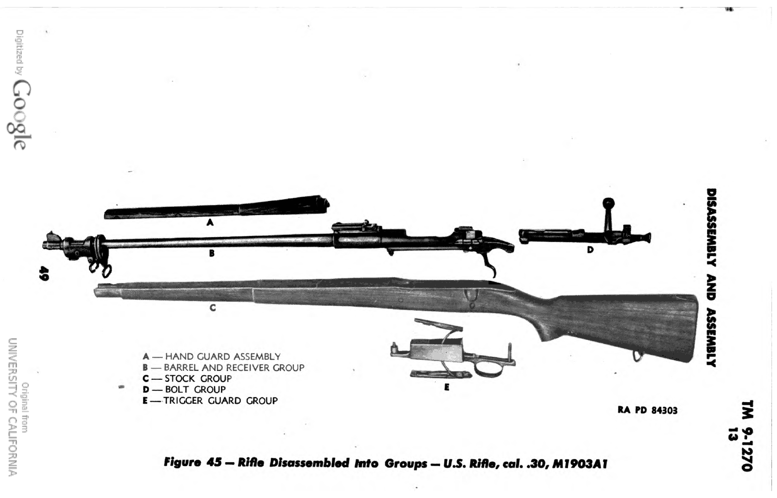
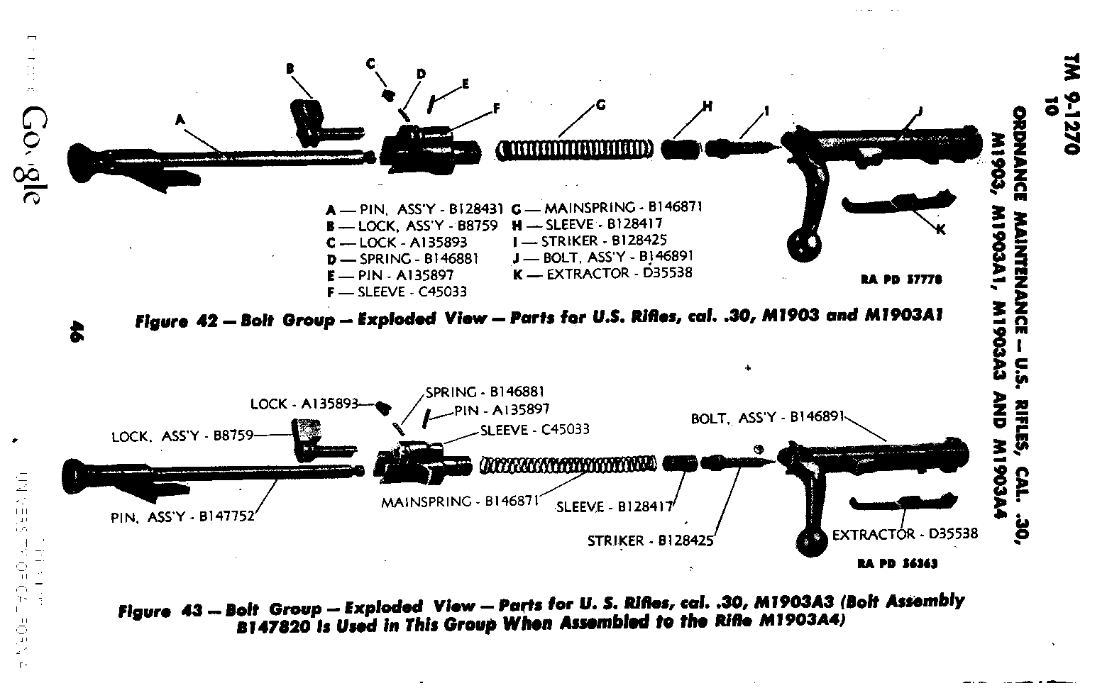
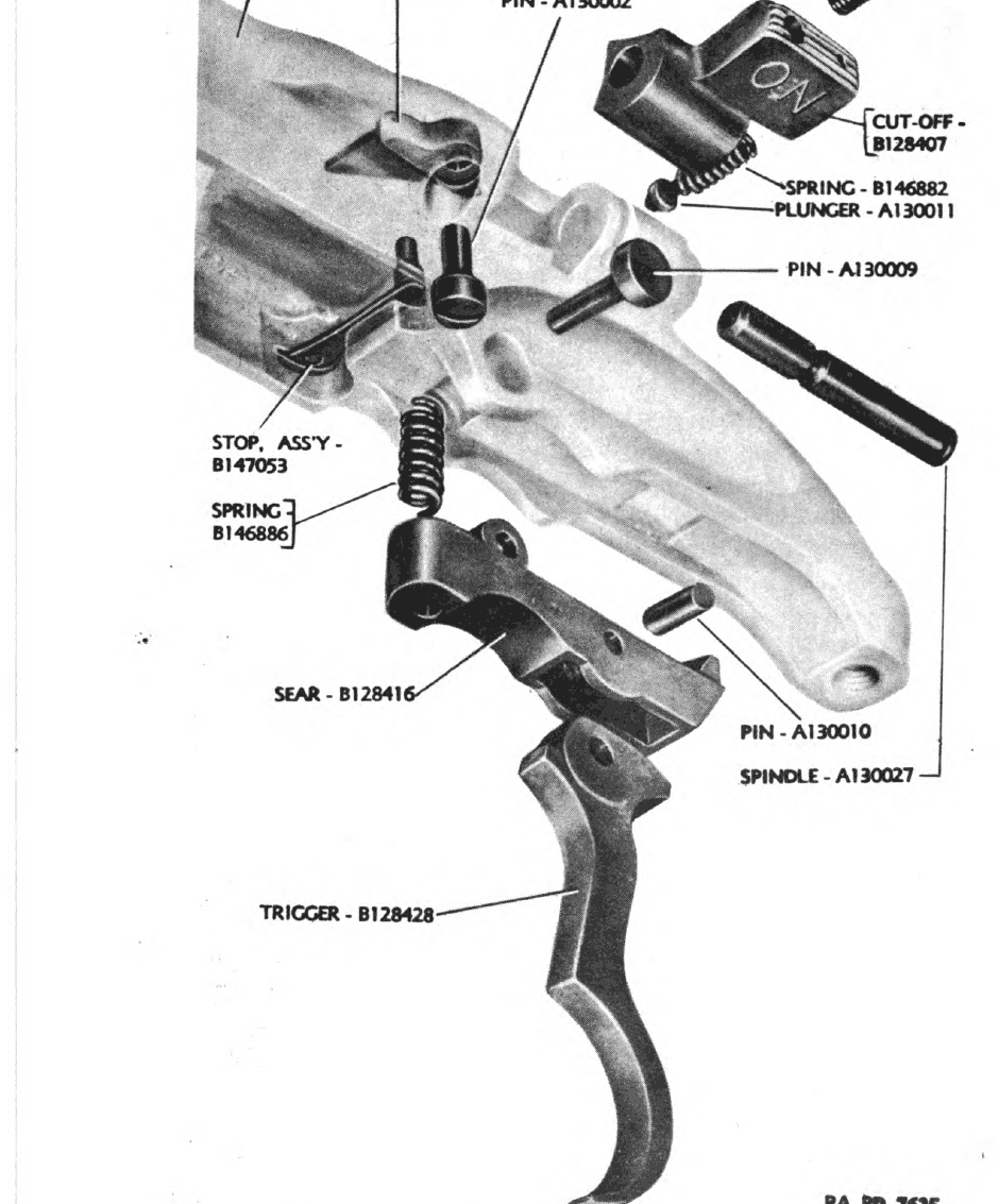
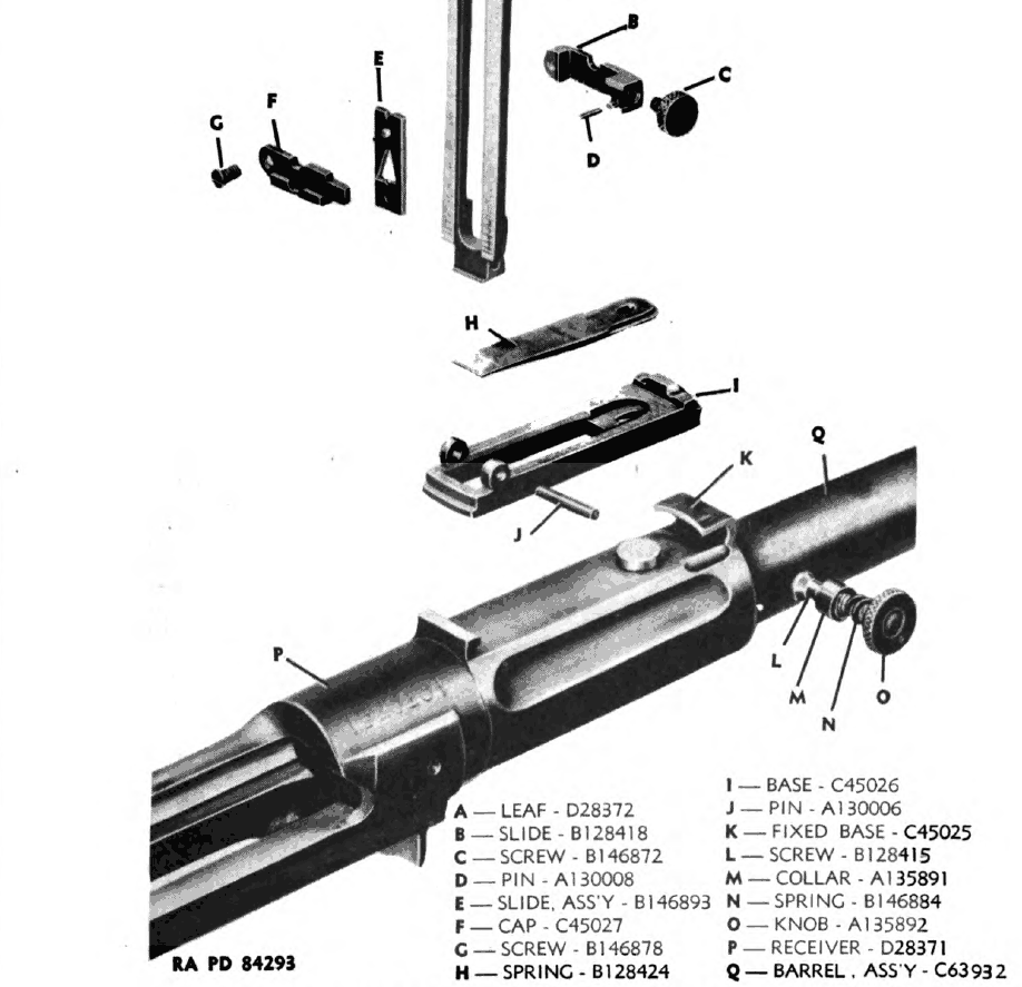
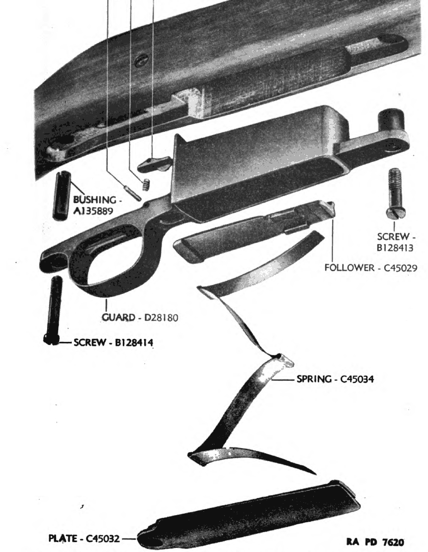
Torque specifications
No sourced torque values from the manufacturer are recorded for this firearm. Where a fastener has a specified torque — action screws, scope bases, muzzle devices, barrel nuts — get it from the manufacturer or a gunsmith rather than estimating it.
What the manufacturer does say: The official military manuals give no torque value. They say: "The stock should fit the rifle snugly at only two points, namely, in the immediate vicinity of the front and rear guard screws." (TM 9-1270 Ordnance Maintenance: U.S. Rifles, cal. .30, M1903, M1903A1, M1903A3 and M1903A4 (1944), p. 87 (PDF p. 88), stock distortion)
Function check
- Verify the rifle is unloaded — chamber and magazine — before each check.
- Cycle the bolt and confirm it cocks and closes fully into battery.
- With the action cocked, engage the safety and press the trigger. The striker must not release.
- Disengage the safety without touching the trigger. The striker must not release.
- Press the trigger and confirm the striker releases with a firm snap.
- Load dummy rounds and confirm they feed and eject cleanly.
- If you have any doubt about the rifle’s history, have headspace gauged by a gunsmith before firing live ammunition.
- Confirm the magazine cut-off works in all three positions: ON feeds from the magazine, OFF makes the rifle a single loader, and the middle position releases the bolt.
- If your rifle is a low-numbered receiver, do not fire it until it has been evaluated.
Maintenance
Lubrication points
- Bolt lugs and raceways
- Cocking cam surfaces
- Extractor
- Trigger and sear contact
Cleaning notes
Surplus ammunition of this era is frequently corrosively primed. After shooting it, flush the bore, bolt face, and gas system with hot soapy water or a water-based solvent the same day, dry completely, then oil. Keep the firing pin channel clean and dry — a pin held forward by congealed cosmoline causes slam fires.
Suggested inspection interval: roughly every 300 rounds. This is a general guideline, not a manufacturer specification.
Wear parts to inspect
Firing pin and its protrusion · Extractor · Bolt lugs · Crown (inspect for cleaning rod wear) · Magazine follower and spring
Common issues
| Symptom | Likely cause | What to do |
|---|---|---|
| Light strikes or misfires | Cosmoline-packed firing pin channel or a weak mainspring | Strip the bolt, clean the firing pin channel completely, and reassemble dry. |
| Sticky bolt lift after firing | Dirty chamber, lacquered surplus ammunition, or excessive headspace | Clean the chamber thoroughly. If it persists, have headspace checked. see a gunsmith |
| Rust appearing days after shooting | Corrosive primer residue | Clean with a water-based solvent the same day, dry, and oil. |
| Bolt will not come out | Magazine cut-off not in the middle position | Set the cut-off to its middle position. This is the most common cause. |
| Uncertainty about receiver serial number | Low-numbered single heat-treated receivers have a documented failure history | Check the serial number and have a low-numbered rifle evaluated before firing it. see a gunsmith |
Also covers
The procedures above are reported to apply to: M1903A1 · M1903A3 · Remington and Smith-Corona wartime production. Verify against the manual for your specific model.
Similar manual of arms
Sourcing
- Confidence
- medium — Drawn from reliable secondary sources and consistent across references, but not confirmed against a primary source.
- Verification
- Community reviewed only
- Last updated
- 2026-10-29
References
Every source this page draws on, with its web address so you can read it yourself. Numbers in brackets elsewhere on the page point here.
- [1] FM 23-10: U.S. Rifle, Caliber .30, M1903 — U.S. War Department military technical manual primary source
- [2] TM 9-1270: U.S. Rifles, Caliber .30, M1903, M1903A1, M1903A3 — U.S. Department of the Army military technical manual primary source
- [3] TM 9-1270 Ordnance Maintenance: U.S. Rifles, cal. .30, M1903, M1903A1, M1903A3 and M1903A4 (1944) — War Department (US Army), 1944 military technical manual primary source
https://archive.org/details/1944TM9-1270 (checked 2026-09-27) - [4] TM 9-1270 Ordnance Maintenance: U.S. Rifles, Cal. .30, M1903, M1903A1, M1903A3 and M1903A4 — War Department (1944) military technical manual primary source
https://archive.org/download/1944TM9-1270/1944TM9-1270.pdf (checked 2026-10-03) - [5] Description and Rules for the Management of the United States Rifle, Caliber .30, Model of 1903 (Ordnance Dept. No. 1923; March 3, 1904, revised March 20, 1914) — War Department, Office of the Chief of Ordnance (Government Printing Office, 1914); scan at archive.org item 'descriptionrules00unit' military technical manual primary source
https://archive.org/download/descriptionrules00unit/descriptionrules00unit_djvu.txt (checked 2026-10-29)
Notes: The low-numbered receiver issue is the single most important thing in this entry and is well documented in U.S. Army records. The three-position magazine cut-off is the mechanical quirk most likely to stump someone trying to remove the bolt. Bolt replacement expanded on 2026-10-03 from TM 9-1270 para 8c: the follower must be pressed down and the extractor aligned with the lower locking lug, which the previous version omitted.