← All firearms · Printable work order
Winchester Model 1897
- advanced
- Shop tier 3
- medium confidence
- Shotgun
- pump action
- exposed hammer
- slam fire
- historic
- takedown
- no safety
field strip ~5 min · reassembly ~8 min · detail strip ~40 min
Specifications
- Manufacturer
- Winchester Repeating Arms
- Origin
- United States
- Category
- Shotgun
- Action
- Pump action
- Calibers
- 12 gauge, 16 gauge
- Capacity
- 5+1 typical
- Production
- 1897–1957 (discontinued)
- Also known as
- Model 97, Trench Gun, Riot Gun
Model-specific safety
- This shotgun has no trigger disconnector. Holding the trigger down and closing the action WILL fire it. That is how the gun was designed, not a fault — but it means the gun behaves differently from every modern pump, and it is genuinely dangerous if you do not know. Determine by function check whether your gun does this before you load it.
- The Model 97 has an EXPOSED HAMMER. You can see and feel its state, which is useful — but it also means the hammer can be struck or snagged. There is no manual safety on this gun at all; the half-cock notch is a hammer rest.
- Unloading a tube magazine takes several cycles. Verify the chamber and the tube.
- Takedown models separate the barrel and magazine assembly from the receiver by rotating them after releasing a takedown screw. Solid-frame models do not. Identify which you have.
- These guns are 65 to 125 years old. Have one of unknown history checked by a gunsmith before firing, and do not fire modern high-pressure or steel shot loads in a barrel never designed for them.
Under spring tension
- Magazine tube spring
- Hammer spring
- Action spring
Easily lost parts
Takedown screw · Action slide lock · Carrier components
Tools
| Tool | Required | Used for | Substitute |
|---|---|---|---|
| Hollow-ground screwdrivers | Optional | Takedown model adjustment and any screw work. |
Shop difficulty
Shop tier 3 Tier 3 — hardest among shotguns, for the full job: strip to the parts that get coated and put it back together working. 81 key-numbered parts, an exposed-hammer carrier that holds the hammer, mainspring, sear and slide lock, and a reassembly with several held springs (mainspring to hammer stirrup, trigger on its spring, extractor plunger) plus keyed wire-spring retainers and a riveted shell guide plate. Many small screws that are not interchangeable.
Parts: 81 numbered parts (complete Model 97 take-down gun per the Radocy 'Takedown Guide' exploded view legend (keys 1-81); forend wood and buttstock are drawn but not numbered ('Parts Not Shown: Forend Wood and Buttstock'), s), from Winchester 97 Takedown Guide (Made Easy series) — parts list and 39-step takedown — Radocy takedown guide (PDF hosted by indaginibalistiche.it), p. 2 indaginibalistiche.it [4].
Bench time: about 80 min to strip, 120 min to rebuild (estimate). Radocy's 39-step takedown: carrier (hammer, mainspring, sear, slide lock), trigger guard, bolt (slide hook, firing pin, retractor, extractors), shell stops, carrier release button, ejector, magazine; rebuild long for the mainspring/stirrup and slide-lock spring.
Small parts: 12 pins, 13 springs, 2 detents or plungers (counted by name in the same list: pins = 12 magazine locking pin, 22 action slide lock release plunger pin, 24 trigger pin, 33 extractor pin left, 39 firing pin stop pin, 50 carrier pin, 60 mainspring)
What comes off for coating
- Barrel / magazine / slide: magazine locking pin and quarter turn, barrel and slide assembly, magazine end cap screws, ring and spring, action slide and spring
- Receiver: carrier pin stop screw and carrier pivot pin, trigger crosspin, trigger and spring, carrier (hammer cocked, release pressed), trigger guard unit, slide hook screw and action slide hook, breech bolt, ejector screw and ejector, shell stops and springs, carrier release button and its wire spring
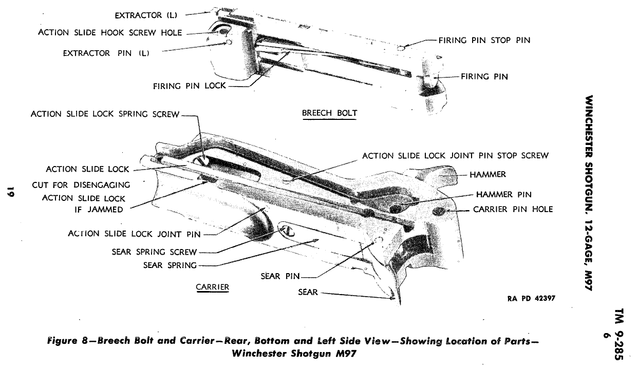
- Carrier: sear spring screw and spring, sear pin and sear, action slide lock spring screw, joint pin stop screw, joint pin, lock and spring, slide lock release plunger, mainspring tension screw, mainspring pin, hammer pin, hammer and mainspring, shell guide plate (riveted; leave)
- Breech bolt: firing pin crosspin and firing pin, retractor screw, retractor and spring, left extractor pin and extractor, right extractor, plunger and spring
- Stock: butt plate, stock bolt
Special tools
- Stock tool or long-shank screwdriver — Stock bolt
- Slim drift — Action slide lock joint pin through the slide-track access hole
- Sharp-nosed pliers and very small probe — Carrier release button wire spring
Known pain points
- Reassembling the carrier lockwork, the mainspring has to be kept engaged in the hammer stirrup, holding the hammer back for tension, while the sear spring screw goes back in. (reassembly)
Source: Winchester 97 Takedown Guide (Made Easy series) — parts list and 39-step takedown — Radocy takedown guide (PDF hosted by indaginibalistiche.it) indaginibalistiche.it [4] — “Be surethe main- spring engagesin the hammerstirrupbefore replacing step#24. Pull back on the hammer to keep the tensionon the stimrp/spring engagement.” - The carrier release button is held inside the receiver by a round wire spring keyed into a tiny hole; it is released by pushing the tip in with a very small tool while moving it with sharp-nosed pliers inside the receiver. (both)
Source: Winchester 97 Takedown Guide (Made Easy series) — parts list and 39-step takedown — Radocy takedown guide (PDF hosted by indaginibalistiche.it) indaginibalistiche.it [4] — “The carrierreleasebutton is retainedinside the receiverby a round wire spring,that is keyed into a tiny hole in the receiverwall.” - The trigger must be pressed down against its spring until the holes line up for the trigger pin. (reassembly)
Source: TM 9-285, Shotguns, All Types — War Department archive.org [3] — “Press trigger down against spring until pin hole in trigger alines” - The right extractor plunger and spring are under tension and must be held while the extractor is lifted out or refitted. (both)
Source: Winchester 97 Takedown Guide (Made Easy series) — parts list and 39-step takedown — Radocy takedown guide (PDF hosted by indaginibalistiche.it) indaginibalistiche.it [4] — “Keep the plungerunder control, slowly releasethe spring tension,and remove the plunger and spring toward the front.” - The carrier only comes out with the hammer cocked, the action slide lock release plunger held in and the carrier pried down through the ejection port. (disassembly)
Source: TM 9-285, Shotguns, All Types — War Department archive.org [3] — “insert a screwdriver through the ejection opening and pry gently on the carrier to start it downward,”
Fit or check on rebuild
- Trigger stop screw setting — If it is moved it must be readjusted so the trigger travels far enough to release the sear.
Source: TM 9-285, Shotguns, All Types — War Department archive.org [3] — “The stop screw should not be removed. This screw is used to limit rear-” - Takedown joint adjusted tight — A loose takedown joint is dangerous and batters the gun.
- Function check: safety, trigger/sear release, disconnector and feeding with dummy rounds — Standard after any detail strip; a mis-assembled sear or disconnector can double or fail to fire.
This is Pew-Takedown's rating, not the manufacturer's. How tiers are rated. Forum reports are owners' experience, not specifications.
Procedures
Clear and Make Safe
Clear & Make SafeExposed hammer, no safety, and it may slam fire. Check all three states.
- Point the muzzle in a safe direction and keep your finger off the trigger.
- Note the hammer position. There is no manual safety on this gun — the hammer is the indicator.WarningHalf-cock is a hammer rest, not a safety.
- Press the action slide lock and pull the forend rearward to open the action.Removed at this step:
Chambered shell, if present - Cycle the action repeatedly, catching each shell, until no more feed from the magazine tube.
- With the action open, inspect the chamber and look up the magazine tube with a light.WarningChamber and tube, both.
- Physically confirm the chamber is empty, then lower the hammer carefully with the chamber confirmed empty.WarningLower the hammer under control with the muzzle in a safe direction.
- Remove all live ammunition from the work area.
Field Strip — Takedown Models
Field StripTakedown models separate into two halves. Solid-frame guns do not.
- Complete the Clear and Make Safe procedure.
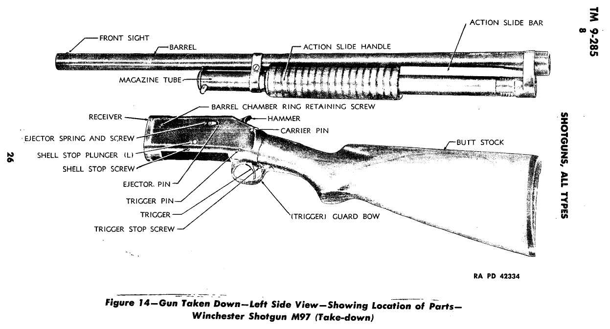
- On a takedown model, release the takedown screw at the front of the receiver.WarningSolid-frame guns have no takedown joint. Do not force anything.Removed at this step:
(screw released) - Pull the action slide lock, move the forend partway rearward, then rotate the barrel and magazine assembly a quarter turn and separate it from the receiver.Removed at this step:
Barrel and magazine tube assembly - Clean the bore from the breech end of the separated barrel, and clean the bolt face, chamber, and receiver interior.
- Stop here. The Model 97 action has many small parts in a specific order and parts are scarce.WarningIf the gun is malfunctioning, take it to a gunsmith who knows pre-war Winchesters.
Remove the carrier group
Detail Strip tools required gunsmith recommendedRemoves the carrier (which carries the hammer, sear and action slide lock) from the receiver after the barrel, magazine and action slide group are off. TM 9-285 assigns this to the using arm (troop level): par. 1c says disassembly and assembly 'will be undertaken only under the supervision of an officer or the chief mechanic', and the field-inspection paragraph limits using troops to the removal and replacement of groups described here. Anything further (adjustment, stoning, trigger work, headspace) goes to ordnance personnel. TM 9-285 allows this to using troops only under the supervision of
Follows TM 9-285, Shotguns, All Types — War Department, par. 8 a (3), pp. 25, 28 archive.org [3]
- Remove the barrel, magazine and action slide group (take-down gun), or the magazine and action slide group (solid-frame gun), first.
- Unscrew the carrier pin stop screw, visible in the left top wall of the carrier just to the rear of the hammer tang.Removed at this step:
Carrier pin stop screw - Drift out the carrier pin, which runs through both receiver walls just below the carrier seat.Removed at this step:
Carrier pin - Remove the shell guide stop screw from the lower rear extremity of the right-hand wall of the receiver.Removed at this step:
Shell guide stop screw - With the hammer cocked, depress the action slide lock release plunger pin in the right wall of the receiver so the lock does not catch on the receiver wall.
- Insert a screwdriver through the ejection opening and pry gently on the carrier to start it downward.TipIf the release plunger will not work, put a small screwdriver blade into the cut in the lower left forward face of the carrier and pry the action slide lock inward.
- Rotate the carrier down and out of the receiver through the lower opening.Removed at this step:
Carrier group
Remove the breech bolt group
Detail Strip tools required gunsmith recommendedWith the carrier out, the action slide hook is unscrewed from the bolt and the bolt slides out the rear of the receiver. TM 9-285 assigns this to the using arm (troop level): par. 1c says disassembly and assembly 'will be undertaken only under the supervision of an officer or the chief mechanic', and the field-inspection paragraph limits using troops to the removal and replacement of groups described here. Anything further (adjustment, stoning, trigger work, headspace) goes to ordnance personnel. TM 9-285 allows this to using troops only under the supervision of an officer or the chief mechani
Follows TM 9-285, Shotguns, All Types — War Department, par. 8 a (4), p. 28 archive.org [3]
- Remove the carrier group first.
- With the breech bolt fully forward, remove the action slide hook screw from the right forward face of the breech bolt.Removed at this step:
Action slide hook screw - Reach into the receiver and remove the action slide hook from the left side of the breech bolt.Removed at this step:
Action slide hook - Slide the breech bolt group to the rear out of the receiver.Removed at this step:
Breech bolt group
Remove the butt stock and trigger guard bow group
Detail Strip tools required gunsmith recommendedThe manual says this group ordinarily need not come out for cleaning. The butt stock comes off first (through-bolt), then the trigger pin is drifted out and the guard bow slides out the rear. TM 9-285 assigns this to the using arm (troop level): par. 1c says disassembly and assembly 'will be undertaken only under the supervision of an officer or the chief mechanic', and the field-inspection paragraph limits using troops to the removal and replacement of groups described here. Anything further (adjustment, stoning, trigger work, headspace) goes to ordnance personnel. TM 9-285 allows this to usi
Follows TM 9-285, Shotguns, All Types — War Department, par. 8 a (5), p. 28 archive.org [3]
- Remove the butt plate screws and the butt plate.Removed at this step:
Butt plate screwsButt plate - With a long-shanked screwdriver, turn the butt stock bolt (now visible in the hole in the stock) counterclockwise to disengage it from the receiver tang.Removed at this step:
Butt stock bolt - Pull the butt stock to the rear off the receiver.Removed at this step:
Butt stock - With a pin drift, drive the trigger pin out of the lower rear end of the receiver.Removed at this step:
Trigger pin - Pull the guard bow to the rear out of the receiver.Removed at this step:
Trigger guard bow group - Remove the trigger and trigger spring from the guard bow.WarningDo not remove the stop screw. It limits the rearward travel of the trigger, which must move far enough to disengage the sear from the hammer.Removed at this step:
TriggerTrigger spring
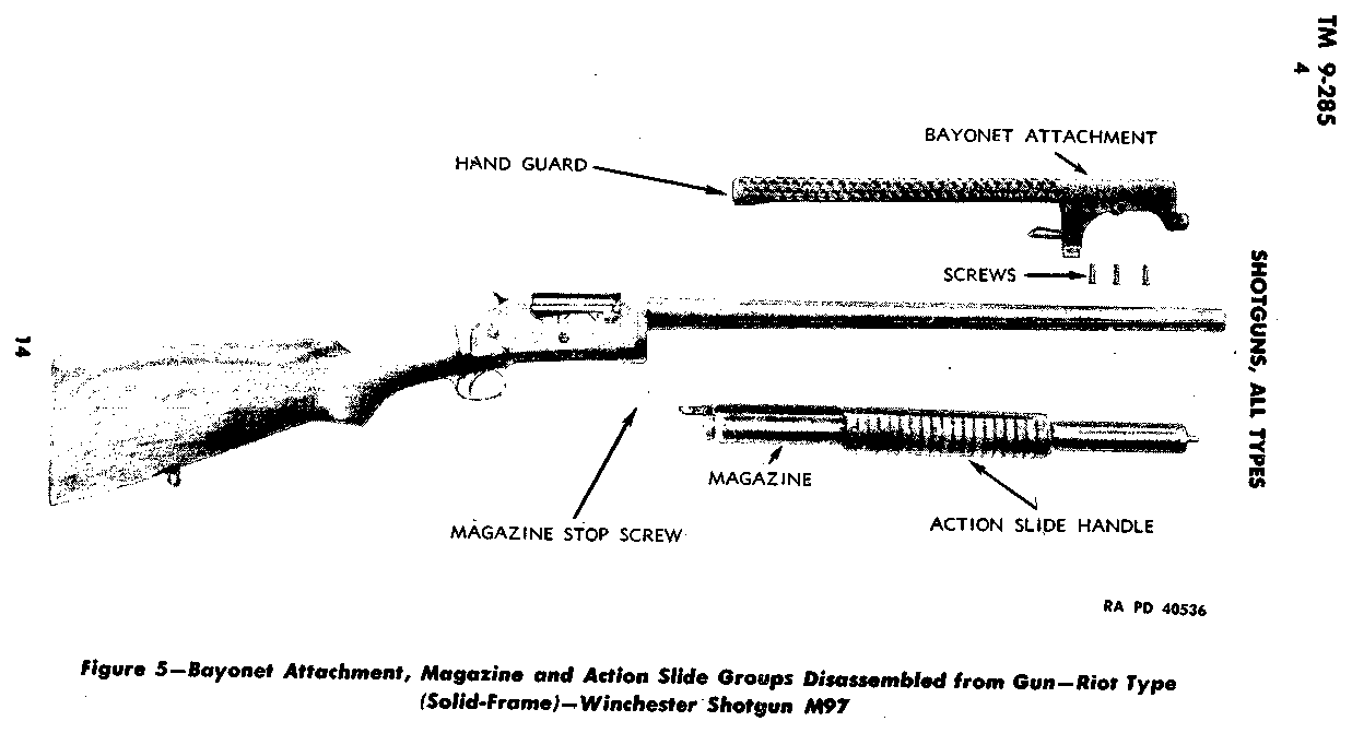
Remove the bayonet attachment and magazine (solid-frame riot gun)
Detail Strip tools requiredMilitary riot (trench) gun only. On the solid-frame gun the barrel stays in the receiver; the bayonet attachment and the screwed-in magazine with the action slide must come off before the receiver groups can be removed. TM 9-285 assigns this to the using arm (troop level): par. 1c says disassembly and assembly 'will be undertaken only under the supervision of an officer or the chief mechanic', and the field-inspection paragraph limits using troops to the removal and replacement of groups described here. Anything further (adjustment, stoning, trigger work, headspace) goes to ordnance personnel.
Applies to: Solid-frame riot gun with bayonet attachment (military)
Follows TM 9-285, Shotguns, All Types — War Department, par. 8 a (1), pp. 24-25 archive.org [3]
- Unscrew and remove the three transverse screws from the bayonet attachment.Removed at this step:
Bayonet attachment screws (3) - Drive the bayonet attachment forward off the barrel.WarningThe barrel of the early solid-frame gun is screwed into the receiver at manufacture and should not be removed.Removed at this step:
Bayonet attachment and hand guard - Lock the action by pushing the action slide handle fully forward.
- Remove the magazine stop screw from the lower forward end of the right side of the receiver.Removed at this step:
Magazine stop screw - Engage the stud and hole in the end of the magazine plug with an improvised tool (a pin-and-hole tool or a rod bent to an L) and turn the magazine counterclockwise out of the receiver.
- Withdraw the magazine with the action slide group attached.Removed at this step:
Magazine and action slide group
Replace the trigger guard bow group and butt stock
Detail Reassembly tools required gunsmith recommendedReverses the guard bow removal; the trigger is held down against its spring while the pin goes in. TM 9-285 assigns this to the using arm (troop level): par. 1c says disassembly and assembly 'will be undertaken only under the supervision of an officer or the chief mechanic', and the field-inspection paragraph limits using troops to the removal and replacement of groups described here. Anything further (adjustment, stoning, trigger work, headspace) goes to ordnance personnel. TM 9-285 allows this to using troops only under the supervision of an officer or the chief mechanic (par. 1c).
Follows TM 9-285, Shotguns, All Types — War Department, par. 9 a (1), pp. 28, 30 archive.org [3]
- Clean, lightly oil and lubricate the parts before replacing them.
- Seat the trigger spring in its aperture in the guard bow.
- Place the trigger on top of the spring with its curved end extending downward through the floor of the guard bow.
- Slide the guard bow into the rear of the receiver, pin hole forward, until the pin holes in guard bow and receiver line up.
- Press the trigger down against its spring until its pin hole lines up with the holes in guard bow and receiver, then insert the trigger pin.
- Drive the trigger pin through until flush.
- Slide the butt stock onto the receiver tang, mating it with the groove in the receiver.
- Replace the butt stock bolt and washer and screw it down tight, turning clockwise.
- Replace the butt plate and screw it down snugly.WarningDo not screw a composition butt plate down too tightly; it can crack and the screw threads in the stock can strip.
Replace the breech bolt group
Detail Reassembly tools required gunsmith recommendedThe breech bolt goes back before the carrier. The action slide hook screw head must stand proud of the bolt to cam the shell guide down. TM 9-285 assigns this to the using arm (troop level): par. 1c says disassembly and assembly 'will be undertaken only under the supervision of an officer or the chief mechanic', and the field-inspection paragraph limits using troops to the removal and replacement of groups described here. Anything further (adjustment, stoning, trigger work, headspace) goes to ordnance personnel. TM 9-285 allows this to using troops only under the supervision of an officer or t
Follows TM 9-285, Shotguns, All Types — War Department, par. 9 a (2), p. 30 archive.org [3]
- Insert the breech bolt group into the rear of the receiver, locking lug forward and down, and push it all the way home.
- Slip the action slide hook into the left side of the breech bolt locking lug so the boss on the hook seats in the counterbore in the lug and the hook lies in its guideway in the left inner wall of the receiver, point down and to the rear.
- Replace the action slide hook screw from the right side of the breech bolt and tighten it.TipThe head of the hook screw should protrude from the right face of the breech bolt at least 1/32 inch so that it cams the shell guide down clear of the ejection opening when the bolt is retracted.
- Slide the breech bolt back and forth several times and check that the hook moves with it.
Replace the carrier group
Detail Reassembly tools required gunsmith recommendedInstalled after the breech bolt, hammer cocked, with the bolt fully forward and the shell guide stop screw out. TM 9-285 assigns this to the using arm (troop level): par. 1c says disassembly and assembly 'will be undertaken only under the supervision of an officer or the chief mechanic', and the field-inspection paragraph limits using troops to the removal and replacement of groups described here. Anything further (adjustment, stoning, trigger work, headspace) goes to ordnance personnel. TM 9-285 allows this to using troops only under the supervision of an officer or the chief mechanic (par. 1
Follows TM 9-285, Shotguns, All Types — War Department, par. 9 a (3), p. 30 archive.org [3]
- Make sure the breech bolt is all the way forward and the shell guide stop screw is out of the right wall of the receiver.
- Cock the hammer.
- Insert the carrier, hammer up and to the rear, through the bottom opening of the receiver and keep moving it rearward until it seats in its recess in the rear wall of the receiver.
- Press firmly up on the carrier until it is completely home behind the locking lug of the breech bolt.
- Insert the carrier pin so its groove is on the left side of the receiver and lined up with the hole for the carrier pin stop screw in the left top of the carrier body, to the left rear of the hammer.
- Replace the carrier pin stop screw.
- Replace the shell guide stop screw in its hole in the right wall of the receiver just ahead of the trigger pin.TipThis screw has a pin end; its head should sit flush with the face of the receiver.
Replace the magazine and bayonet attachment (solid-frame riot gun)
Detail Reassembly tools requiredMilitary riot gun only. The carrier is locked up behind the bolt first so the slide bar can enter the carrier cam aperture. TM 9-285 assigns this to the using arm (troop level): par. 1c says disassembly and assembly 'will be undertaken only under the supervision of an officer or the chief mechanic', and the field-inspection paragraph limits using troops to the removal and replacement of groups described here. Anything further (adjustment, stoning, trigger work, headspace) goes to ordnance personnel.
Applies to: Solid-frame riot gun with bayonet attachment (military)
Follows TM 9-285, Shotguns, All Types — War Department, par. 9 a (4) and (6), pp. 31-32 archive.org [3]
- With the hammer forward in the fired position, move the breech bolt forward and lock the carrier behind it by pressing upward on the carrier until it is behind the locking shoulder of the bolt.
- With the action slide on the magazine, hold the magazine along the underside of the barrel and insert the rear end of the slide bar into the bar opening in the left forward face of the receiver.
- Push the slide bar rearward so that it enters the cam aperture in the carrier.
- Mate the magazine threads with those in the receiver, taking care not to cross-thread them.
- Screw the magazine tightly into the receiver, turning clockwise, until the stop screw holes in receiver and magazine line up, then replace the stop screw.TipThe improvised tool used for removal can be used to tighten the magazine.
- Slide the bayonet attachment group onto the muzzle end of the barrel with the sling swivel to the rear and the sight up.
- Mate the hole in the rear of the attachment lug with the stud on the magazine plug, and adjust the attachment until its screw holes line up with the screw grooves in the underside of the barrel.
- Replace the screws and screw them in tightly.
- Check the attachment for level seating and for interference of the hand guard with the action slide handle.
- Pull the action slide to the rear as far as it will go and operate it several times to test the mechanism and the locking of the breech bolt and slide.
Reassembly
Reassembly- Align the barrel and magazine assembly with the receiver and rotate it a quarter turn to engage.
- Tighten the takedown screw until the two halves are snug with no perceptible play.WarningA loose takedown joint is dangerous and will batter the gun. Adjust it rather than shooting it loose.
- Cycle the action several times and perform the function check.
Diagrams
public domainThese are reproduced from government technical manuals, which are not subject to copyright. Manufacturer manual diagrams are not reproduced here — the entry links to the manual instead.
Torque specifications
No sourced torque values from the manufacturer are recorded for this firearm. Where a fastener has a specified torque — action screws, scope bases, muzzle devices, barrel nuts — get it from the manufacturer or a gunsmith rather than estimating it.
What the manufacturer does say: The manufacturer's documents give no torque value. They say: "Then replace butt stock bolt and washer, and screw down tight by turning clockwise. The butt plate can then be replaced and screwed down snugly." (TM 9-285 Shotguns, All Types (War Department Technical Manual, 21 Sept 1942), PDF p. 31) "Replace action slide hook screw from right side of breech bolt, and tighten." (TM 9-285 Shotguns, All Types (War Department Technical Manual, 21 Sept 1942), PDF p. 31)
Parts list
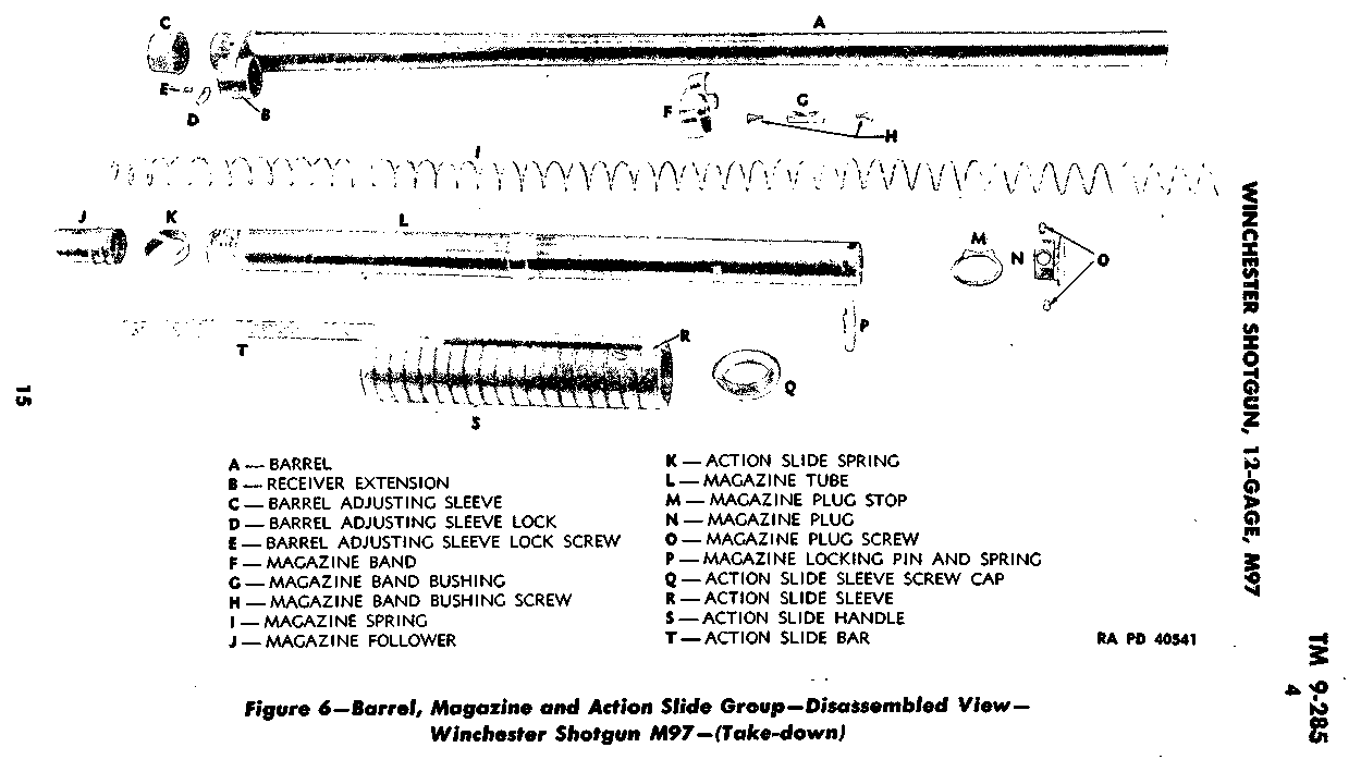
Transcribed from the manufacturer's parts list (TM 9-285, Shotguns, All Types — War Department, p. 15 archive.org [3]) — PARTIAL: TM 9-285 Figure 6 lettered legend, "Barrel, Magazine and Action Slide Group—Disassembled View—Winchester Shotgun M97 (Take-down)". Receiver, breech bolt, carrier and trigger parts have no legend list.. Key numbers refer to the exploded view in that document.
20 parts
| Key | Part | Part no. | Qty | Group |
|---|---|---|---|---|
| A | BARREL | 1 | Barrel, Magazine and Action Slide Group | |
| B | RECEIVER EXTENSION | 1 | Barrel, Magazine and Action Slide Group | |
| C | BARREL ADJUSTING SLEEVE | 1 | Barrel, Magazine and Action Slide Group | |
| D | BARREL ADJUSTING SLEEVE LOCK | 1 | Barrel, Magazine and Action Slide Group | |
| E | BARREL ADJUSTING SLEEVE LOCK SCREW | 1 | Barrel, Magazine and Action Slide Group | |
| F | MAGAZINE BAND | 1 | Barrel, Magazine and Action Slide Group | |
| G | MAGAZINE BAND BUSHING | 1 | Barrel, Magazine and Action Slide Group | |
| H | MAGAZINE BAND BUSHING SCREW | 1 | Barrel, Magazine and Action Slide Group | |
| I | MAGAZINE SPRING | 1 | Barrel, Magazine and Action Slide Group | |
| J | MAGAZINE FOLLOWER | 1 | Barrel, Magazine and Action Slide Group | |
| K | ACTION SLIDE SPRING | 1 | Barrel, Magazine and Action Slide Group | |
| L | MAGAZINE TUBE | 1 | Barrel, Magazine and Action Slide Group | |
| M | MAGAZINE PLUG STOP | 1 | Barrel, Magazine and Action Slide Group | |
| N | MAGAZINE PLUG | 1 | Barrel, Magazine and Action Slide Group | |
| O | MAGAZINE PLUG SCREW | 1 | Barrel, Magazine and Action Slide Group | |
| P | MAGAZINE LOCKING PIN AND SPRING | 1 | Barrel, Magazine and Action Slide Group | |
| Q | ACTION SLIDE SLEEVE SCREW CAP | 1 | Barrel, Magazine and Action Slide Group | |
| R | ACTION SLIDE SLEEVE | 1 | Barrel, Magazine and Action Slide Group | |
| S | ACTION SLIDE HANDLE | 1 | Barrel, Magazine and Action Slide Group | |
| T | ACTION SLIDE BAR | 1 | Barrel, Magazine and Action Slide Group |
Function check
- Verify the shotgun is unloaded — chamber and magazine tube — before each step.
- Cycle the action fully and confirm it locks closed.
- With the hammer cocked, engage the safety and press the trigger. The hammer must not fall.
- Disengage the safety and press the trigger. The hammer should fall.
- Load two dummy shells into the magazine and confirm they feed and eject one at a time.
- Confirm the magazine cap or takedown fastener is tight.
- Determine whether your gun slam fires: with the hammer cocked and the trigger held to the rear, cycle the action fully. If the hammer falls as the action closes, the gun has no disconnector.
- Know the answer before you load it.
- On a takedown model, confirm the joint is snug with no play.
Maintenance
Lubrication points
- Action bars in their receiver grooves
- Bolt body and locking lug
- Magazine tube exterior
- Hammer and sear pivots
Cleaning notes
Keep the magazine tube interior clean and dry rather than oiled — oil there collects plastic wad residue and slows the follower. Plastic fouling in the chamber and bore is normal with shotshells.
Suggested inspection interval: roughly every 1000 rounds. This is a general guideline, not a manufacturer specification.
Wear parts to inspect
Extractor · Shell latches · Magazine spring · Action bars
Common issues
| Symptom | Likely cause | What to do |
|---|---|---|
| Gun fires each time the action closes with the trigger held | No trigger disconnector — original design | This is how the gun was built. Handle it accordingly. see a gunsmith |
| Play at the takedown joint | Takedown screw needs adjustment | Adjust the screw. Do not keep shooting it loose. see a gunsmith |
Also covers
The procedures above are reported to apply to: Model 1897 Riot and Trench configurations · Model 1893 (earlier, weaker action — do not fire smokeless loads). Verify against the manual for your specific model.
Similar manual of arms
Sourcing
- Confidence
- medium — Drawn from reliable secondary sources and consistent across references, but not confirmed against a primary source.
- Verification
- Community reviewed only
- Last updated
- 2026-10-29
References
Every source this page draws on, with its web address so you can read it yourself. Numbers in brackets elsewhere on the page point here.
- [1] Winchester Model 1897 Shotgun Instructions — Winchester Repeating Arms manufacturer manual primary source
- [2] TM 9-285 Shotguns, All Types (War Department Technical Manual, 21 Sept 1942) — U.S. War Department military technical manual primary source
https://archive.org/details/TM9-285 (checked 2026-09-27) - [3] TM 9-285, Shotguns, All Types — War Department (1942) military technical manual primary source
https://archive.org/download/TM9-285/TM9-285.pdf (checked 2026-09-27) - [4] Winchester 97 Takedown Guide (Made Easy series) — parts list and 39-step takedown — Radocy takedown guide (PDF hosted by indaginibalistiche.it) book secondary source
https://www.indaginibalistiche.it/utlities/manuali/winchester_97_EN.pdf (checked 2026-10-29)
Notes: The slam-fire capability and the complete absence of a manual safety are the defining handling facts about this gun. The Model 1893 that preceded it was designed for black powder and must not be fired with smokeless loads — confirm which you have.