← All firearms · Printable work order
M1 Carbine
- moderate
- Shop tier 3
- high confidence
- Carbine
- surplus
- short stroke piston
- historic
- light rifle
field strip ~5 min · reassembly ~8 min · detail strip ~40 min
Specifications
- Manufacturer
- Springfield Armory (U.S. Government Arsenal)
- Origin
- United States
- Category
- Carbine
- Action
- Gas, short-stroke piston
- Calibers
- .30 Carbine
- Capacity
- 15 or 30 rounds
- Production
- 1942–1945 (surplus)
- Also known as
- U.S. Carbine, Caliber .30, M1, M1A1 Carbine
Model-specific safety
- The recoil spring is not captive and is under tension. It will launch if released carelessly.
- The M1 Carbine is not a small M1 Garand. It uses a short-stroke gas tappet system and a completely different operating rod and bolt arrangement.
- The gas piston nut is staked and torqued at the factory. Do not attempt to remove it without the correct tool — it is not part of routine maintenance.
- Surplus carbines have often been rebuilt with mixed parts across several manufacturers. Have headspace checked on any carbine of unknown history before firing.
- The safety on early carbines is a push-button located next to the magazine release, and the two have been confused with predictable results. Later carbines use a lever safety.
- The upper band screw is LOOSENED about 1/8 inch, not removed. The band then slides off over its retaining spring.
- FM 23-7 limits the individual soldier to a named list of parts. Anything beyond it is done only under the supervision of an officer or ordnance personnel, and bolt disassembly needs special tools.
- Cock the hammer before removing the trigger group, or the guard assembling pin will not drive out cleanly.
If it will not go back together
Common ways this firearm resists reassembly, and what is actually wrong. Forcing a part that will not seat is how firearms get damaged.
-
The stock will not come off, or will not go back on.
Why The safety is not pushed to the left, so the receiver is still caught on the stock abutment.
Fix Push the safety to the left, then raise the muzzle end of the barrel out of the stock — or lower it in, refitting.
Forcing it Levering the barrel out against the abutment cracks the stock at the recoil shoulder.
-
The upper band will not slide off.
Why The upper band screw was not loosened, or the upper band retaining spring is not depressed.
Fix Loosen the screw about 1/8 inch — do not remove it — then depress the retaining spring with the base of a cartridge and slide the band off over it.
-
The guard assembling pin will not start, or the trigger group will not come free.
Why The hammer is not cocked, or the trigger group is being pulled downward instead of sideways.
Fix Cock the hammer first by cycling the operating slide. Start the pin with the small end of the guide rod, then slide the trigger group to the left out of its undercut grooves.
Forcing it Driving the pin against a forward hammer burrs the pin and the trigger housing.
-
The operating spring will not go back into the receiver well.
Why It is being pushed straight in rather than entered from the left with the guide rod raised.
Fix Fit the spring onto the guide rod, enter the spring into its well from the left, then seat the rod's end into its seat in the operating slide.
Under spring tension
- Recoil spring
- Hammer spring in the trigger housing
- Magazine spring
Easily lost parts
Recoil spring and guide · Operating slide · Trigger housing retaining pin · Bolt camming lug
Tools
| Tool | Required | Used for | Substitute |
|---|---|---|---|
| A carbine cartridge | Optional | FM 23-7 uses the rim to loosen the upper band screw and the base to depress the upper band retaining spring. | A dummy or fired case is the sensible substitute. Do not use a live round. |
| Operating spring guide rod | Optional | Its small end is the FM's own punch for starting the guard assembling pin. |
Shop difficulty
Shop tier 3 Tier 3 — hardest among rifles and carbines, for the full job: strip to the parts that get coated and put it back together working. About 45 basic parts, but the trigger housing alone holds the hammer spring and plunger, sear spring, trigger spring and two spring-loaded plungers. The bolt has a special Ordnance disassembly tool. The entry records four separate reassembly traps (stock, band, guard pin, op spring).
Parts: 43 numbered parts (Basic nomenclature, barrel/receiver, stock, bolt and trigger housing groups (magazine excluded); adapted from TM 9-1276), from .30 Caliber Carbine Basic Nomenclature — M1CarbinesInc.com, p. n/a (web page) m1carbinesinc.com [4].
Bench time: about 50 min to strip, 75 min to rebuild (estimate). Estimate: field strip plus trigger housing (hammer, sear, trigger, safety, mag catch and their springs/plungers), bolt with the bolt tool, slide stop, recoil plate, band and sights. Rebuild longer for the trigger housing springs and plungers and the slide/bolt fit.
Small parts: 3 pins, 10 springs, 4 detents or plungers (counted from the basic nomenclature list in partCount (combined rows split))
What comes off for coating
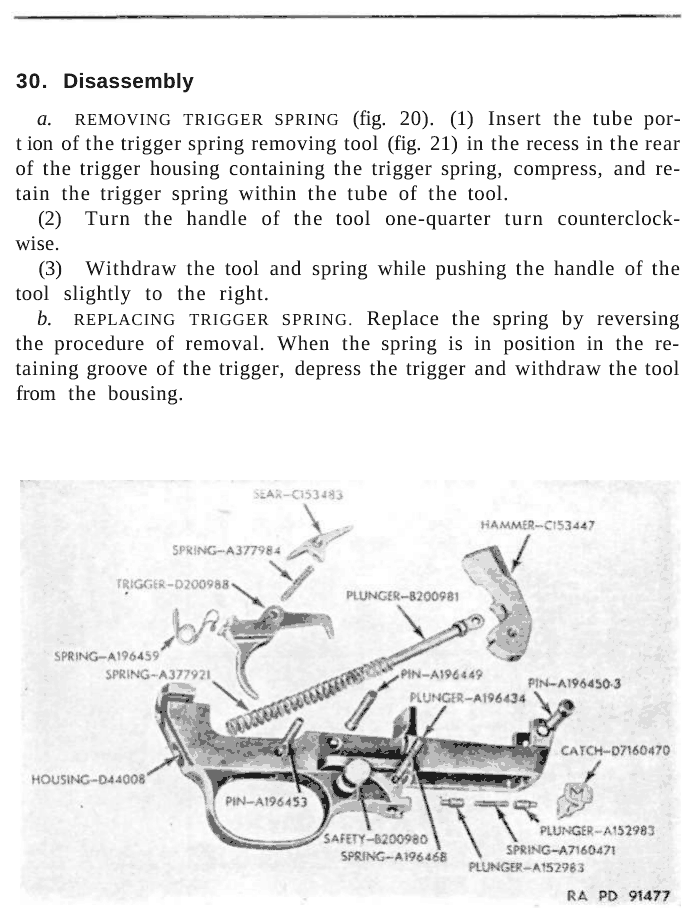
- Trigger housing: trigger housing pin, hammer, hammer pin, spring and plunger, sear and sear spring, trigger, trigger pin and spring, safety, plunger and spring, magazine catch, plunger and spring — drift punch
- Barrel and receiver: operating slide spring and guide, slide, bolt (extractor, extractor plunger and spring, ejector and spring, firing pin), slide stop and spring, rear sight, front sight key/pin, gas piston nut and piston (optional) — M1 carbine bolt tool
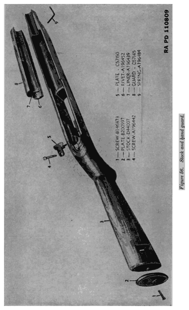
- Stock group: barrel band and front band spring, handguard, recoil plate and screw, buttplate and screw
Special tools
- M1 carbine bolt disassembly tool — Extractor/ejector removal and reassembly
- Drift punches — Trigger housing pin, hammer pin, trigger pin
- Gas piston nut wrench (only if the piston comes out) — Gas piston nut
- Rear sight assembling tool / sight pusher — Adjustable rear sight
Known pain points
- Stripping the bolt (extractor, extractor plunger and spring, ejector and spring, firing pin) is done with a dedicated bolt tool that holds the ejector plunger while the extractor comes out. (both)
Source: TM 9-1276 Carbines, Cal. .30, M1, M1A1, M2, and M3 (Ordnance Maintenance) — War Department archive.org [3] — “TOOL, DISASSEMBLING, BOLT 41-T-3019-625” - The trigger housing strips into several sprung parts. The sear is under spring tension on its pin, and the trigger return spring is the fiddly one to get back. (reassembly)
Source: TFB FIELD STRIP: M1 Carbine — The Firearm Blog thefirearmblog.com [5] — “However, the following isn’t too difficult other than replacing the trigger return spring.” - Getting the slide (op rod) off the bolt and out of its guide rails takes a practised wiggle and has to be repeated in reverse. (both)
Source: TFB FIELD STRIP: M1 Carbine — The Firearm Blog thefirearmblog.com [5] — “This step is a bit tricky. The charging handle/operating rod need to be separated from the bolt and removed from its guide rails under the barrel.” - Stoning or fitting the sear and hammer notches to correct trigger pull was ordnance-only work. (reassembly)
Source: TM 9-1276 Carbines, Cal. .30, M1, M1A1, M2, and M3 (Ordnance Maintenance) — War Department archive.org [3] — “Stoning should be done only by trained ordnance personnel.”
See also 4 documented reassembly problems and their fixes.
Fit or check on rebuild
- Trigger pull and sear engagement — TM 9-1276 checks trigger pull and has sear/hammer notch work done by ordnance
Source: TM 9-1276 Carbines, Cal. .30, M1, M1A1, M2, and M3 (Ordnance Maintenance) — War Department archive.org [3] — “Stoning should be done only by trained ordnance personnel.” - Recoil plate / receiver lug fit — A loose recoil plate lets the barrel and receiver group shift in the stock
Source: TM 9-1276 Carbines, Cal. .30, M1, M1A1, M2, and M3 (Ordnance Maintenance) — War Department archive.org [3] — “Looseness of recoil plate in stock, or receiver locking lug in undercut in plate, will cause barrel and receiver group to become loose.” - Rear sight re-zero — The sight is staked/pressed on and the carbine must be re-zeroed
This is Pew-Takedown's rating, not the manufacturer's. How tiers are rated. Forum reports are owners' experience, not specifications.
Procedures
Clear and Make Safe
Clear & Make Safe- Point the muzzle in a safe direction and keep your finger off the trigger.
- Place the selector on safe if the design allows it with the action in its current state.
- Press the magazine release and remove the magazine.Removed at this step:
Magazine - Pull the charging handle fully to the rear and lock the action open if the rifle has a hold-open.
- Inspect the chamber and magazine well with a light, then physically confirm the chamber is empty.WarningLook and feel. Both, every time.
- Remove all live ammunition from the work area.
Field Strip
Field StripThree groups: trigger housing, barrelled action, and stock.
- Complete the Clear and Make Safe procedure, and remove the magazine.WarningFM 23-7's caution: do not let the magazine drop to the ground.
- Remove the sling and the oiler from the recess in the butt of the stock.Removed at this step:
SlingOiler - Rest the carbine on a level surface with the head of the upper band screw up and to the left. Using the rim of a cartridge, loosen the upper band screw about 1/8 inch.WarningLoosen only. The screw does not come out.
- Turn the barrel over, depress the upper band retaining spring with the base of the cartridge, and slide the upper band over the retaining spring and off the stock.Removed at this step:
Upper band - Slide the hand guard forward until its rear end disengages from the groove in the front of the receiver, and remove it from the barrel.Removed at this step:
Hand guard - Grasp the small of the stock with the right hand and the barrel with the left, palm up. Push the safety to the LEFT.WarningThe safety must go left or the receiver will not release from the stock abutment.
- Raise the muzzle end of the barrel out of the stock until the receiver is released from the stock abutment, then remove the stock.Removed at this step:
Stock assembly - Lay the barrel and attached assemblies on a level surface, muzzle to the left, operating slide handle UP.
- Grasp the operating spring guide rod, pull it to the rear to disengage it from its seat in the operating slide, raise it slightly, and withdraw the operating spring to the LEFT from its well in the receiver. Separate the spring from the guide rod.Removed at this step:
Operating slide springGuide rod - Cock the hammer by pulling the operating slide to the rear and pushing it forward.
- Turn the barrel so the operating slide handle is DOWN. Start the guard assembling pin with the small end of the operating spring guide rod and pull the pin out from the far side.Removed at this step:
Guard assembling pin - Remove the trigger group assembly by sliding it to the LEFT, disengaging its undercut grooves from the corresponding grooves in the receiver.WarningIt slides sideways out of its grooves. It does not drop down and off.Removed at this step:
Trigger group assembly - Draw the operating slide rearward to its dismount notch, rotate it outward and lift it off its track.Removed at this step:
Operating slide - Slide the bolt rearward, rotate it, and lift it out of the receiver.Removed at this step:
Bolt assembly - Stop here.WarningFM 23-7 states that further disassembly is made only under the supervision of an officer or ordnance personnel, and that disassembling the bolt requires special tools.
Remove the trigger spring from the trigger housing
Detail Strip tools required gunsmith recommendedRemoves the trigger spring from the removed trigger housing group with the trigger spring removing tool (TM 9-1276 para 30a). This is the only trigger housing disassembly the 1947 manual describes. TM 9-1276 is written for ordnance maintenance personnel and leaves to FM 23-7 only what the using arms do (para 1); FM 23-7 (1942) para 10a forbids the soldier further disassembly except under the supervision of an officer or ordnance personnel.
Follows TM 9-1276 Carbines, Cal. .30, M1, M1A1, M2, and M3 (Ordnance Maintenance) — War Department, para 30a, p. 42 archive.org [3]
- Insert the tube portion of the trigger spring removing tool in the recess in the rear of the trigger housing that holds the trigger spring, compressing the spring and retaining it within the tube of the tool.
- Turn the handle of the tool one-quarter turn counterclockwise.
- Withdraw the tool and spring while pushing the handle of the tool slightly to the right.Removed at this step:
Trigger spring
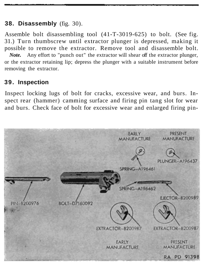
Disassemble the bolt
Detail Strip tools required gunsmith recommendedDepresses the extractor plunger with the bolt disassembling tool to free the extractor, then strips the bolt (TM 9-1276 para 38; parts from fig. 30). TM 9-1276 is written for ordnance maintenance personnel and leaves to FM 23-7 only what the using arms do (para 1); FM 23-7 (1942) para 10a forbids the soldier further disassembly except under the supervision of an officer or ordnance personnel.
Follows TM 9-1276 Carbines, Cal. .30, M1, M1A1, M2, and M3 (Ordnance Maintenance) — War Department, para 38, p. 55 archive.org [3]
- Assemble the bolt disassembling tool (41-T-3019-625) to the bolt.
- Turn the thumbscrew until the extractor plunger is depressed.WarningAny effort to punch out the extractor will shear off the extractor plunger or the extractor retaining lip; depress the plunger before removing the extractor.
- Remove the extractor.Removed at this step:
Extractor - Remove the tool.
- Remove the extractor plunger and spring, the ejector and ejector spring, and the firing pin from the bolt.TipFigure 30 shows the parts.Removed at this step:
Extractor plungerExtractor plunger springEjectorEjector springFiring pin
Remove the front sight
Detail Strip tools required gunsmith recommendedDrives out the front sight pin and pulls the front sight off the muzzle with the front sight removing tool (TM 9-1276 para 42). Barrel work with special tools; the 1953 revision makes it depot maintenance only. TM 9-1276 is written for ordnance maintenance personnel and leaves to FM 23-7 only what the using arms do (para 1); FM 23-7 (1942) para 10a forbids the soldier further disassembly except under the supervision of an officer or ordnance personnel.
Follows TM 9-1276 Carbines, Cal. .30, M1, M1A1, M2, and M3 (Ordnance Maintenance) — War Department, para 42, p. 58 archive.org [3]
- Break the front sight pin loose with a tapered punch.WarningDo not remove the front sight unless necessary; the sight body is crimped over both ends of the pin and the key is staked in its keyway.
- Drive the pin out with a 3/32-inch drift.Removed at this step:
Front sight pin - Position the front sight removing tool (41-T-3318-500) over the front sight, hooking it on the rear of the sight.
- Enter the pilot of the tool screw into the end of the barrel and remove the front sight by turning the handle of the tool.Removed at this step:
Front sight
Remove the adjustable rear sight
Detail Strip tools required gunsmith recommendedPushes the adjustable rear sight out of the receiver dovetail with the rear sight assembling tool (TM 9-1276 para 46c). TM 9-1276 is written for ordnance maintenance personnel and leaves to FM 23-7 only what the using arms do (para 1); FM 23-7 (1942) para 10a forbids the soldier further disassembly except under the supervision of an officer or ordnance personnel.
Follows TM 9-1276 Carbines, Cal. .30, M1, M1A1, M2, and M3 (Ordnance Maintenance) — War Department, para 46c, p. 61 archive.org [3]
- Make a scribe mark on the receiver directly opposite the long line on the index plate, for alignment in assembly.
- Place the assembling tool on the receiver with the right-hand jack screw retracted to its extreme position and out of the way.
- Place the guide of the assembling tool against the side of the sight and put the connector in place in the dovetail guide.WarningOn stamped type sights, use the spacer to prevent distortion of the sight base wings.
- Tighten the left-hand jack screw.
- When pressure becomes excessive, tap the connector with a brass hammer and take up the slack, repeating until the sight is removed.Removed at this step:
Rear sight assembly
Remove the early L-type rear sight
Detail Strip tools required gunsmith recommendedDrifts the early flip-type L rear sight out of the receiver dovetail; the manual says all L-type sights are to be replaced by the adjustable sight (TM 9-1276 para 46b). TM 9-1276 is written for ordnance maintenance personnel and leaves to FM 23-7 only what the using arms do (para 1); FM 23-7 (1942) para 10a forbids the soldier further disassembly except under the supervision of an officer or ordnance personnel.
Applies to: Early carbines with the L-type rear sight
Follows TM 9-1276 Carbines, Cal. .30, M1, M1A1, M2, and M3 (Ordnance Maintenance) — War Department, para 46b, p. 61 archive.org [3]
- Clamp the rear end of the receiver in a jaw-protected vise.
- Place the rear sight aligning gauge over the L-type sight and make a scribe mark on the rear of the receiver, for aligning the new sight.
- Drift the old sight out of the dovetail slot from left to right with a brass drift.TipThe dovetail tapers to the left; the letter S on the left face of the base marks the small end. On carbines of recent manufacture the base is staked in place.Removed at this step:
L-type rear sight
Remove the gas piston and piston nut
Detail Strip tools required gunsmith recommendedUnscrews the staked piston nut from the gas cylinder and slides the gas piston out (TM 9-1276 para 50b). The gas cylinder itself is not removed. TM 9-1276 is written for ordnance maintenance personnel and leaves to FM 23-7 only what the using arms do (para 1); FM 23-7 (1942) para 10a forbids the soldier further disassembly except under the supervision of an officer or ordnance personnel.
Follows TM 9-1276 Carbines, Cal. .30, M1, M1A1, M2, and M3 (Ordnance Maintenance) — War Department, para 50b, p. 71 archive.org [3]
- Clamp the barrel firmly in a vise with protected jaws.
- Unscrew the piston nut from the gas cylinder with the gas piston nut removing tool M5, or the gas piston holder and spanner wrench.WarningThe nut is staked in place; do not bur or twist its prongs or the piston will not move freely.Removed at this step:
Gas piston nut - Elevate the muzzle of the barrel and slide the piston out of the gas cylinder.WarningDo not remove the gas cylinder; an unserviceable cylinder means the barrel assembly is replaced at a base shop.TipIf the piston will not slide out, tap the cylinder lightly with a wooden block.Removed at this step:
Gas piston
Remove the front band locking spring, recoil plate and butt plate
Detail Strip tools required gunsmith recommendedStrips the one-piece stock: front band locking spring, recoil plate and screw, escutcheon (replacement only) and butt plate (TM 9-1276 para 54a-d). The hand guard liner is riveted and not removed. TM 9-1276 is written for ordnance maintenance personnel and leaves to FM 23-7 only what the using arms do (para 1); FM 23-7 (1942) para 10a forbids the soldier further disassembly except under the supervision of an officer or ordnance personnel.
Applies to: M1 and M2 (one-piece stock; not M1A1)
Follows TM 9-1276 Carbines, Cal. .30, M1, M1A1, M2, and M3 (Ordnance Maintenance) — War Department, para 54a-c, p. 83 archive.org [3]
- Insert a small straight punch in the spring spindle hole in the left side of the forward end of the stock and drive the front band locking spring part way out from left to right.
- Rotate the spring and pull it from the hole.Removed at this step:
Front band locking spring - Unscrew the recoil plate screw counterclockwise until it is clear of the escutcheon threads, then withdraw it from the stock and recoil plate.Removed at this step:
Recoil plate screw - Loosen the recoil plate by tapping lightly on its rear top face with a metal tool.
- Pull the plate directly forward out of its seating recess in the stock.WarningDo not pull up or down; the rear seating lug sits in a horizontal recess cut in the stock.Removed at this step:
Recoil plate - Only to replace the escutcheon, thread the recoil plate screw all the way into it from the under side and pull the escutcheon out of the stock.TipIf it is hard to withdraw, insert a small straight punch from the top of the screw hole and tap the end of the screw lightly, or thread the screw in part way from the top and tap lightly.Removed at this step:
Escutcheon - Unscrew the butt plate screw counterclockwise and remove it from the stock.Removed at this step:
Butt plate screw - Loosen the butt plate by tapping it lightly and pull it to the rear off the stock.WarningIf the butt plate is tight, do not pry it off; tap lightly around the edges until it is loose.Removed at this step:
Butt plate
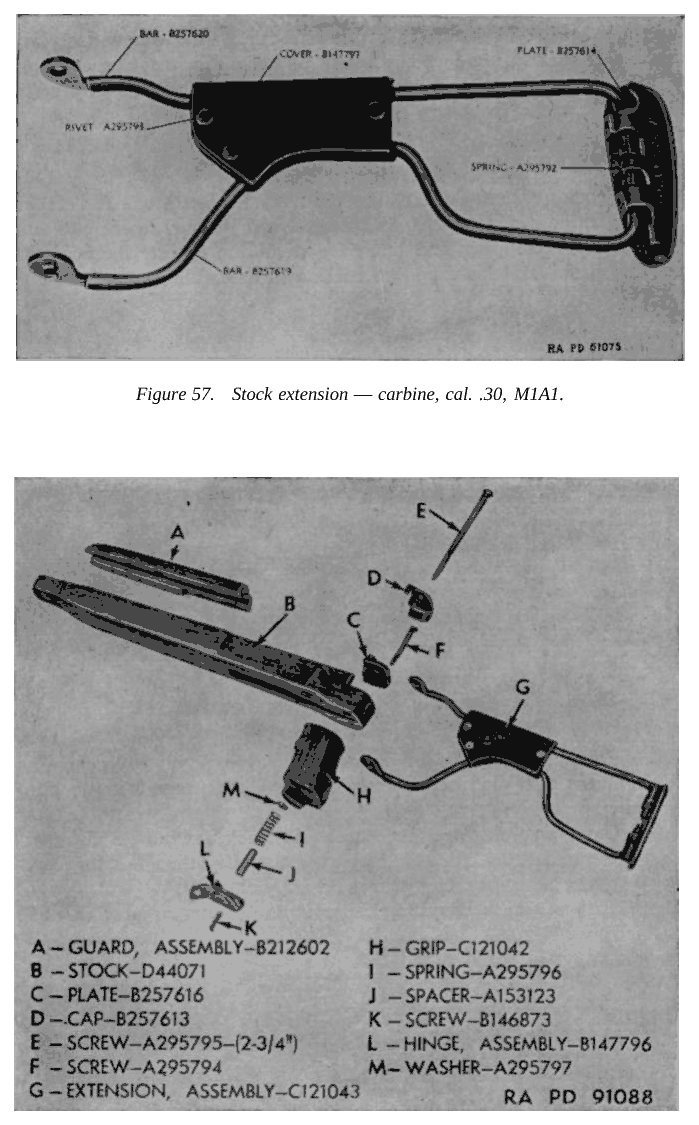
Remove the folding stock extension, grip and recoil plate
Detail Strip tools required gunsmith recommendedTakes the M1A1 folding stock extension off the stock and removes the pistol grip and recoil plate (TM 9-1276 para 54e). TM 9-1276 is written for ordnance maintenance personnel and leaves to FM 23-7 only what the using arms do (para 1); FM 23-7 (1942) para 10a forbids the soldier further disassembly except under the supervision of an officer or ordnance personnel.
Applies to: M1A1
Follows TM 9-1276 Carbines, Cal. .30, M1, M1A1, M2, and M3 (Ordnance Maintenance) — War Department, para 54e, pp. 83 and 86 archive.org [3]
- Remove the lower hinge screw from the lower end of the stock grip by turning it counterclockwise.Removed at this step:
Lower hinge screw - With the stock extension extended, unscrew the hinge screw projecting from the upper face of the recoil plate cap, turning it counterclockwise until it is disengaged from the lower hinge nut.
- Pull the hinge screw up and out of the grip, then lift off the recoil plate cap and lower hinge.Removed at this step:
Hinge screwRecoil plate capLower hinge - With a flat-ended punch, push the hinge screw spacer out of the hole in the lock on the end of the lower bar, up into the coil spring.
- Pull the stock extension to the rear from the stock and remove the grip spring, hinge screw spacer and grip spring washer from the countersunk hole in the lower end of the grip.WarningTake care that the spring does not fly out and the washer is not lost.Removed at this step:
Stock extensionGrip springHinge screw spacerGrip spring washer - Unscrew the grip screw counterclockwise from the top of the recoil plate and remove the grip and recoil plate.Removed at this step:
Grip screwGripRecoil plate
Disassemble the magazine
Detail Strip tools required gunsmith recommendedSlides the base off and rotates the follower out of the tube (TM 9-1276 para 58). The manual says not to disassemble the magazine except for cleaning or salvage. TM 9-1276 is written for ordnance maintenance personnel and leaves to FM 23-7 only what the using arms do (para 1); FM 23-7 (1942) para 10a forbids the soldier further disassembly except under the supervision of an officer or ordnance personnel.
Follows TM 9-1276 Carbines, Cal. .30, M1, M1A1, M2, and M3 (Ordnance Maintenance) — War Department, para 58, p. 95 archive.org [3]
- Grasp the magazine in the left hand with the base up and the rounded face toward your body.
- With the left thumb, press up on the forward (rounded) end of the magazine base until the base can be slid out of its retaining grooves.WarningRestrain the magazine spring as the base is removed.TipMovement can be started with the rim of a cartridge or a screwdriver point in the indent in the top of the base; ribbed bases with an overhanging lip are removed by inserting a screwdriver under the lip and pulling up and out.
- Withdraw the base and the spring from the tube.Removed at this step:
Magazine baseMagazine spring - Reverse the tube and slide the follower to the bottom of the tube.
- Grasp the long rear flange of the follower and rotate it down out of the tube.WarningDo not force the follower.TipIf it sticks, press on its rear end with a screwdriver from the top of the tube until the stop flange is clear, pressing up on the opposite end to help it rotate.Removed at this step:
Follower
Install the trigger spring
Detail Reassembly tools required gunsmith recommendedReplaces the trigger spring by reversing the removal procedure, as TM 9-1276 para 30b says, then depresses the trigger to release the tool. TM 9-1276 is written for ordnance maintenance personnel and leaves to FM 23-7 only what the using arms do (para 1); FM 23-7 (1942) para 10a forbids the soldier further disassembly except under the supervision of an officer or ordnance personnel.
Follows TM 9-1276 Carbines, Cal. .30, M1, M1A1, M2, and M3 (Ordnance Maintenance) — War Department, para 30b, p. 42 archive.org [3]
- With the trigger spring compressed in the tube of the tool, insert the tool in the recess in the rear of the trigger housing, pushing the handle slightly to the right.TipThe manual says only to reverse the removal procedure; steps 1 and 2 are that reversal.
- Turn the handle of the tool one-quarter turn clockwise.
- When the spring is in position in the retaining groove of the trigger, depress the trigger and withdraw the tool from the housing.
Reassemble the bolt
Detail Reassembly tools required gunsmith recommendedTM 9-1276 para 40 says to assemble the bolt in the reverse order of disassembly, with a note on positioning the extractor plunger. TM 9-1276 is written for ordnance maintenance personnel and leaves to FM 23-7 only what the using arms do (para 1); FM 23-7 (1942) para 10a forbids the soldier further disassembly except under the supervision of an officer or ordnance personnel.
Follows TM 9-1276 Carbines, Cal. .30, M1, M1A1, M2, and M3 (Ordnance Maintenance) — War Department, para 40, p. 57 archive.org [3]
- Insert the firing pin, the ejector and ejector spring, and the extractor spring and plunger into the bolt.
- Position the plunger so that its flat surface matches the flat surface on the extractor retaining lip.
- Assemble the bolt disassembling tool to the bolt and turn the thumbscrew until the extractor plunger is depressed.
- Install the extractor.
- Remove the tool.
Install the front sight
Detail Reassembly tools required gunsmith recommendedSeats and stakes the front sight key, drives the sight on with the assembling tool, pins and stakes it (TM 9-1276 para 45). The front band must already be on the barrel. TM 9-1276 is written for ordnance maintenance personnel and leaves to FM 23-7 only what the using arms do (para 1); FM 23-7 (1942) para 10a forbids the soldier further disassembly except under the supervision of an officer or ordnance personnel.
Follows TM 9-1276 Carbines, Cal. .30, M1, M1A1, M2, and M3 (Ordnance Maintenance) — War Department, para 45, p. 59 archive.org [3]
- Make sure the front band is assembled on the barrel.
- Place the front sight key in the keyway in the top of the barrel at the muzzle with its pin notch facing up.
- Tap the key snugly toward the front end of the keyway.
- Stake the rear end of the keyway securely against the key.
- Slide the front sight on the barrel with the sloping faces of the wings to the rear.
- Using the front sight assembling tool (41-T-3017-625), mate keyway and key and drive the sight onto the barrel until the pinhole in the sight aligns with the pin notch in the key.
- Install the front sight pin.
- Stake the metal of the sight over both ends of the pin.
- Tap the sight forward and restake the keyway behind the key.TipThe key must fit tightly in the keyway.
Install the adjustable rear sight
Detail Reassembly tools required gunsmith recommendedPresses a new adjustable rear sight into the receiver dovetail with the assembling tool and a torque wrench held between 18 and 54 inch-pounds, aligns it to the scribe mark and stakes it (TM 9-1276 para 49). TM 9-1276 is written for ordnance maintenance personnel and leaves to FM 23-7 only what the using arms do (para 1); FM 23-7 (1942) para 10a forbids the soldier further disassembly except under the supervision of an officer or ordnance personnel.
Follows TM 9-1276 Carbines, Cal. .30, M1, M1A1, M2, and M3 (Ordnance Maintenance) — War Department, para 49, pp. 64-67 archive.org [3]
- Press the new rear sight into the right side of the dovetail by hand.
- Center the aperture ramp on the sight base.
- If installing a stamped type sight, put the spacer attached to the assembling tool in place to reinforce the side wings of the sight.
- Place the assembling tool on the receiver with the lip of the tool engaging the operating slide guideway in the receiver.
- Move the tool to the rear until its dovetail guide enters the dovetail slot in the receiver.
- Tighten the jack screw by hand until the block of the jack screw is against the side of the sight.
- Insert the torque wrench in the jack screw.
- Move the sight into the dovetail slot with the torque wrench, keeping the reading over 18 inch-pounds and under 54 inch-pounds.WarningTake the reading while the wrench is moving; the starting reading is high. Too much pressure will crack or break the receiver; too little and the sight will work loose under firing. If the reading is outside the limits, put the spacer in place and remove the sight.
- Continue until the zero line of the index plate is aligned with the scribe mark on the rear of the receiver.
- Remove the tool from the receiver.
- Screw the ramp of the sight to the extreme left.
- Place the staking fixture: for a machined type sight, firmly against the forward edge of the sight base wings; for a stamped type sight, with its center leg firmly against the windage screw.WarningNever apply pressure to the sight base wings; they carry the windage screw and any distortion will ruin the sight.
- Place the staking punch in the hole in the fixture and rap it lightly with a hammer, holding the punch to the rear so the fixture stays in position.WarningStake only adjacent to the notches or indents on the sight base dovetail; the upper edges of the receiver dovetail are easily sheared.
Reinstall the gas piston and piston nut
Detail Reassembly tools required gunsmith recommendedCleans and lightly oils the cylinder and piston, replaces them and stakes the piston nut lightly (TM 9-1276 paras 52b(1) and 51b(3)). TM 9-1276 is written for ordnance maintenance personnel and leaves to FM 23-7 only what the using arms do (para 1); FM 23-7 (1942) para 10a forbids the soldier further disassembly except under the supervision of an officer or ordnance personnel.
Follows TM 9-1276 Carbines, Cal. .30, M1, M1A1, M2, and M3 (Ordnance Maintenance) — War Department, para 52b(1), p. 78; para 51b(3), pp. 72- archive.org [3]
- Clean the inside of the cylinder and the piston and oil them very lightly.
- Replace the piston in the gas cylinder and screw the piston nut into the cylinder.
- Stake the gas cylinder very lightly into the nut in one of the three places provided.WarningIf the nut is not staked it may work loose during firing.
Install the front band locking spring, recoil plate and butt plate
Detail Reassembly tools required gunsmith recommendedReinstalls the front band locking spring, escutcheon, recoil plate and butt plate, drawing the recoil plate screw tight only after the barrel and receiver group is in the stock (TM 9-1276 para 57a-c). TM 9-1276 is written for ordnance maintenance personnel and leaves to FM 23-7 only what the using arms do (para 1); FM 23-7 (1942) para 10a forbids the soldier further disassembly except under the supervision of an officer or ordnance personnel.
Applies to: M1 and M2 (one-piece stock; not M1A1)
Follows TM 9-1276 Carbines, Cal. .30, M1, M1A1, M2, and M3 (Ordnance Maintenance) — War Department, para 57b, p. 93 archive.org [3]
- Insert the spindle of the front band locking spring into the hole in the right forward end of the stock, drive it to the left and seat the spring fully in its recess.
- If the escutcheon was removed, insert it small end first in its seat in the lower face of the stock grip and tap it in until level and flush with the stock.
- Insert the recoil plate into the rear of the receiver aperture in the stock, bevel face up and tang to the rear, from front to rear and held level so that the seating lug and horizontal recess mate.
- Seat the recoil plate evenly and flush with its recess by tapping lightly.
- Pass the recoil plate screw through the top of the recoil plate and stock grip, thread it into the escutcheon and draw it down part way.
- Assemble the barrel and receiver group to the stock, align it, and draw the recoil plate screw down tight.TipTightening last prevents strain on the parts.
- Place the butt plate on the butt and tap it lightly until solidly and evenly seated.
- Insert the butt plate screw and turn it down snugly.WarningDo not force the screw; the threads in the wood may strip.
Install the grip, recoil plate and folding stock extension
Detail Reassembly tools required gunsmith recommendedRefits the M1A1 grip and recoil plate, then the stock extension, hinge screw and lower hinge, and tests the lock (TM 9-1276 para 57d). TM 9-1276 is written for ordnance maintenance personnel and leaves to FM 23-7 only what the using arms do (para 1); FM 23-7 (1942) para 10a forbids the soldier further disassembly except under the supervision of an officer or ordnance personnel.
Applies to: M1A1
Follows TM 9-1276 Carbines, Cal. .30, M1, M1A1, M2, and M3 (Ordnance Maintenance) — War Department, para 57d, pp. 93-94 archive.org [3]
- Fit the grip to the rear under face of the stock just behind the trigger guard opening, projection pointing downward so the trigger guard bow will fit into the forward face of the grip.
- Seat the recoil plate on top of the rear end of the stock with its undercut lug facing forward, align the screw holes, insert the grip screw and screw it down tightly clockwise.
- Place the grip spring washer in the large counterbored hole in the lower end of the grip and seat the grip spring in the hole on the washer.
- Hold the stock extension with the locking lug on the lower bar facing down, place the upper face of the lock against the lower end of the grip spring and press the lock upward against the spring until the hinge on the upper bar slips over and lies on top of the recoil plate.
- Still holding the lock against the spring, align the holes in spring and lock and insert the hinge screw spacer until it is flush with the lower face of the lock.
- Position the recoil plate cap over the recoil plate and upper hinge so it rests flat on both.
- Insert the hinge screw through the cap and push it down through the hinge, recoil plate, stock, grip, grip spring washer, grip spring, spacer and lock.WarningPush the screw down until its upper shoulder has entered the hole in the upper hinge and is not bearing on the cap or top of the hinge.
- Position the lower hinge assembly over the lock so the locking lug slot in the nut mates with the locking lug on the lock and the sling eyelet faces forward.
- Press the nut and lock upward against the grip spring and turn the hinge screw until its threads catch in the nut, then turn it until the lower hinge shell rests firmly on the lower face of the grip.WarningMake sure the spacer is flush with the lower face of the lock before trying to catch the threads.
- Insert the lower hinge screw in the lower end of the stock grip and turn it clockwise until tight.
- Fold the stock extension to the left against the stock to test the locking.TipThe extension should lock rigidly both fully extended and fully folded, and there should be no movement between stock and grip.
Reassemble the magazine
Detail Reassembly gunsmith recommendedRotates the follower into the tube, inserts the spring and slides the base on, then checks follower orientation (TM 9-1276 para 60). TM 9-1276 is written for ordnance maintenance personnel and leaves to FM 23-7 only what the using arms do (para 1); FM 23-7 (1942) para 10a forbids the soldier further disassembly except under the supervision of an officer or ordnance personnel.
Follows TM 9-1276 Carbines, Cal. .30, M1, M1A1, M2, and M3 (Ordnance Maintenance) — War Department, para 60, pp. 95-97 archive.org [3]
- Insert the short curved flange of the follower into the rear (flat side) of the bottom opening of the magazine tube and rotate the long flange upward into the tube.WarningDo not force it unduly or the magazine will be distorted.TipOn tubes with a lip, press down on the opposite end of the follower and rotate until the long flange snaps under the lip.
- Push the follower to the top of the tube and insert the magazine spring with its long dimension to the rear.
- Compress the spring with the thumb and, starting from the rounded edge of the tube, insert the base square end first, indent projection facing in, under the retaining lips of the tube.TipRibbed bases go on with the ribs facing inward.
- Push the base in until its projection catches on the tube.
- Push the follower down in the tube and release it to test that it moves smoothly under spring action.TipThe ramp on the follower must face the rear of the tube, the flat side with the two nibs for the magazine catch.
Reassembly
Reassembly- Set the bolt into the receiver raceway and slide it forward.
- Engage the operating slide at its dismount notch, rotate it into its track, and slide it forward, engaging the bolt camming lug and the gas piston.
- Slide the trigger housing group into place and insert its retaining pin.
- Set the barrelled action into the stock and install the barrel band and its screw.
- Install the recoil spring and guide into the operating slide.WarningControl the spring throughout.
- Cycle the action several times and perform the function check.
Diagrams
public domainThese are reproduced from government technical manuals, which are not subject to copyright. Manufacturer manual diagrams are not reproduced here — the entry links to the manual instead.
Torque specifications
| Fastener | Torque | Sequence, notes and the source's words | Where it comes from |
|---|---|---|---|
| Rear sight assembling tool jack screw, pressing the adjustable rear sight base into the receiver dovetail | 18–54 in-lb 2–6.1 N·m · 1.5–4.5 ft-lb |
Para 49h: read the torque wrench while it is moving (the starting reading is high). Below 18 inch-pounds the dovetail is oversize and the receiver is peened (para 49v); above 54 inch-pounds the sight base bottom is filed, never the receiver (para 49w). “Be sure reading on torque wrench is over 18 inch-pounds. (2) Be sure reading on torque wrench is under 54 inch-pounds.” |
TM 9-1276 Carbines, Cal. .30, M1, M1A1, M2, and M3 (Ordnance Maintenance) — War Department, para 49h, p. 65 archive.org [3] |
Notes: The official military manuals give no torque value. They say: "Slide the upper band down over the end of the hand guard and stock until it is engaged by the upper band retaining spring. Tighten the upper band screw." (FM 23-7: U.S. Carbine, Caliber .30, M1, PDF p. 18 (leaf 17), assembly)
Function check
- Verify the rifle is unloaded with no magazine inserted before each step.
- Cycle the action by hand and confirm the bolt locks and returns fully to battery.
- With the selector on safe, press the trigger. The hammer or striker must not release.
- Move the selector to fire, cycle the action, and press the trigger. It should release.
- Hold the trigger back, cycle the action, and release slowly to feel the disconnector reset.
- Confirm the magazine seats and locks positively, and that any hold-open engages on an empty magazine.
Maintenance
Lubrication points
- Bolt lugs and camming surfaces
- Operating slide track
- Bolt camming lug
- Hammer and sear pivots
Cleaning notes
The gas tappet system is self-cleaning by design and should not be disassembled for routine maintenance. Some surplus .30 Carbine ammunition is corrosively primed — clean with a water-based solvent the same day if you shoot surplus.
Suggested inspection interval: roughly every 500 rounds. This is a general guideline, not a manufacturer specification.
Wear parts to inspect
Recoil spring · Operating slide · Extractor and ejector · Bolt lugs · Magazine feed lips
Common issues
| Symptom | Likely cause | What to do |
|---|---|---|
| Failure to lock back or short-stroking | Weak recoil spring, fouled gas system, or a worn operating slide | Replace the recoil spring first, then have the gas piston inspected. see a gunsmith |
| Magazine falls out unexpectedly | Worn magazine catch, common on surplus carbines | Replace the magazine catch. see a gunsmith |
| Safety and magazine release confused | Early push-button safety sits beside the magazine release | Know which type your carbine has. Many were converted to the lever safety. |
Also covers
The procedures above are reported to apply to: M1A1 paratrooper carbine · Commercial M1 Carbine reproductions (with differences). Verify against the manual for your specific model.
Similar manual of arms
Sourcing
- Confidence
- high — Cross-checked against a primary source such as the manufacturer's manual or an issuing military technical manual.
- Verification
- Checked against an armorer/technical manual
- Last updated
- 2026-10-29
References
Every source this page draws on, with its web address so you can read it yourself. Numbers in brackets elsewhere on the page point here.
- [1] FM 23-7: U.S. Carbine, Caliber .30, M1 — War Department military technical manual primary source
https://archive.org/details/FM23-7 (checked 2026-09-15) - [2] TM 9-1276: Carbines, Caliber .30, M1, M1A1, M2 and M3 — U.S. Department of the Army military technical manual primary source
- [3] TM 9-1276 Carbines, Cal. .30, M1, M1A1, M2, and M3 (Ordnance Maintenance) — War Department (1947) military technical manual primary source
https://archive.org/download/tm-9-1276-carbines-cal.-.-30-m-1-m-1-a-1-m-2-and-m-3-1947/TM%209-1276%20Carbines%2C%20Cal.%20.30%2C%20M1%2C%20M1A1%2C%20M2%2C%20And%20M3%20%20%201947.pdf (checked 2026-10-03) - [4] .30 Caliber Carbine Basic Nomenclature — M1CarbinesInc.com military technical manual primary source
https://www.m1carbinesinc.com/nomenclature.html (checked 2026-10-29) - [5] TFB FIELD STRIP: M1 Carbine — The Firearm Blog website secondary source
https://www.thefirearmblog.com/blog/2019/06/14/tfb-field-strip-m1-carbine/ (checked 2026-10-29)
Notes: Verified on 2026-09-15 against FM 23-7, the operator's field manual, now cited by URL. The previous procedure had the sequence wrong and has been replaced with the FM's own order: sling and oiler, magazine, hand guard, stock, operating slide spring and guide rod, trigger group, operating slide, bolt. Specific corrections: the upper band screw is loosened about 1/8 inch and not removed, and the band slides off over its retaining spring; the safety must be pushed to the LEFT before the receiver will release from the stock abutment; the hammer must be cocked before the guard assembling pin will drive out; and the trigger group comes out by sliding LEFT out of its undercut grooves rather than dropping down and off. The FM sanctions using a cartridge rim and base as tools and the small end of the guide rod as a punch. TM 9-1276 was also retrieved but is an ordnance-level rebuild manual concerned with inspection tolerances and special tools, not field stripping, so the operator FM is the source used here. FM 23-7 limits the individual soldier to a named list of parts and states that further disassembly happens only under supervision.